Abstract
Raman Spectroscopy is a well-known method for identifying molecules by their spectroscopic “fingerprint”. In Surface Enhanced Raman Scattering (SERS), the presence of nanometallic surfaces in contact with the molecules enormously enhances the spectroscopic signal. Raman enhancing surfaces are often fabricated lithographically or chemically, but the throughput is low and the equipment is expensive. In this work a SERS layer was formed by the self-assembly of silver nanospheres from a hexane suspension onto an imprinted thermoplastic sheet (PET). In addition, the SERS layer was transferred and securely bonded to other surfaces. This is an important attribute for probes into solid specimen. Raman spectra were obtained with Rhodamine 6G (R6G) solution concentrations ranging from 1 mm to 1 nm. The methods described here produced robust and sensitive SERS surfaces with inexpensive equipment, readily available materials, and with no chemical or lithographic steps. These may be critical concerns to laboratories faced with diminishing funding resources.
1. Introduction
The Raman spectroscopy of light inelastically scattered by molecules is an important tool for identifying those molecules [1,2,3]. Raman spectroscopy has been extensively explored for various applications, including in vivo molecular diagnosis. Eberhardt et al. suggested that Raman spectroscopy has a major advantage for in vivo diagnosis of plagues due to its ability to provide information about the biochemical composition of the plague [1]. They further stated that diagnosing the biochemistry of the plague is important for a more personalized medication. Raman spectroscopy for in vivo diagnosis is usually performed with probes. A probe is needed to bring the instrumentation to the specimen. Zhao et al. demonstrated the in vivo detection of skin cancer using an optical fiber-based Raman probe in conjunction with an automated internal algorithm analysis of the spectrum [4]. Taketani et al. used a Raman endoscope for the in situ diagnosis of the response of colorectal tumors to anti-cancer drugs [5].
The signal strength in Raman spectroscopy is weak, but in Surface Enhanced Raman Scattering (SERS) it is strengthened up to millions of times by close contact between the molecules and nanoscale metallic structures [3,6,7,8,9,10,11,12]. SERS also improves the specificity of Raman spectroscopy [1]. This implies that SERS could be used for the early diagnosis of diseases and physiological disorders. SERS is an important non-invasive diagnostic tool for molecular diagnosis.
The instrumentation for SERS may be configured in two ways:
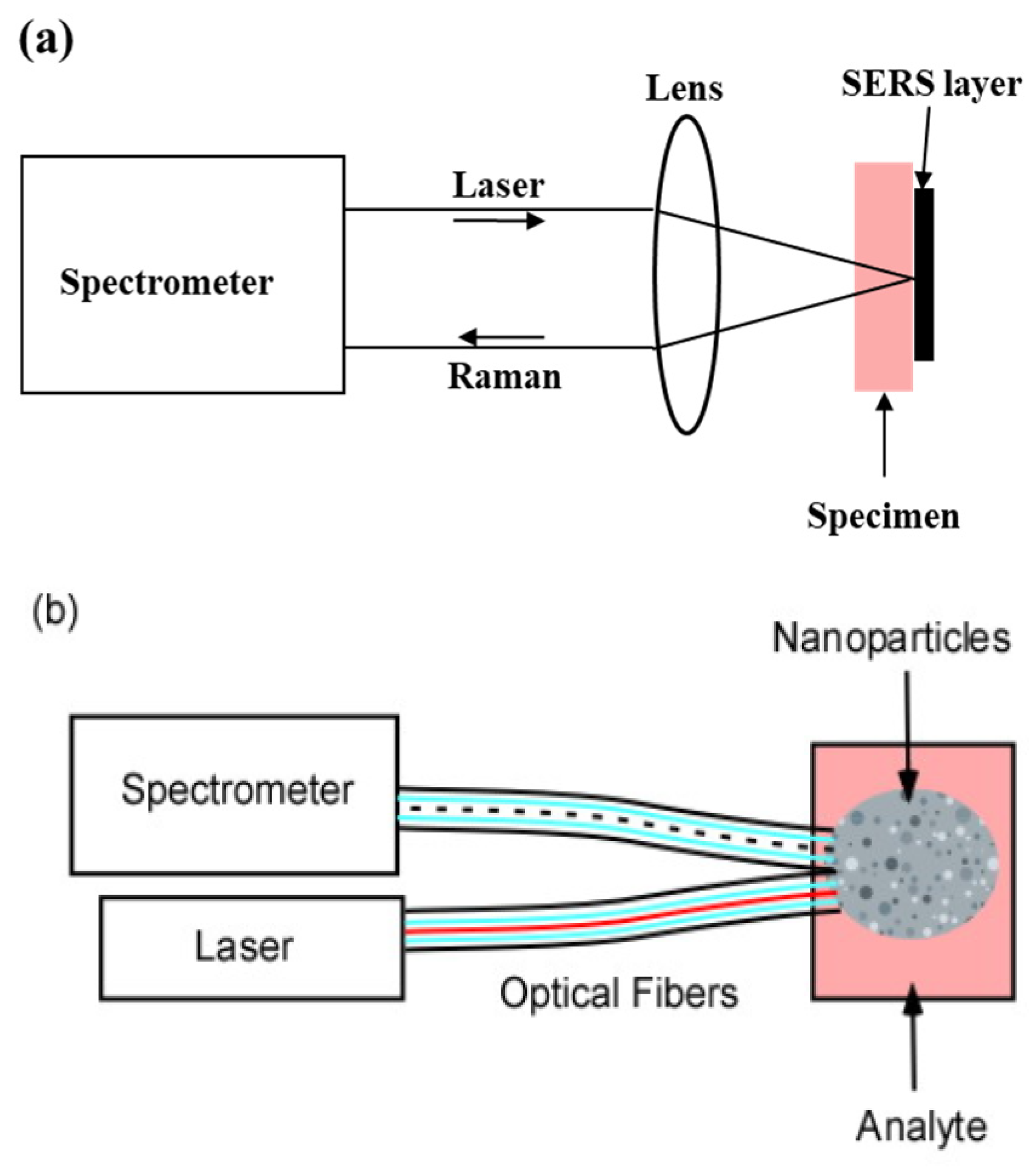
In vitro samples may be brought to a stationary instrument equipped with the SERS layer (Figure 1a). The layer may consist of a substrate on which pairs of conductors are separated by gaps as small as 2 to 4 nanometers. The conductors act as antennae for the incident light. They concentrate the electric field in the gaps and produce “hot spots” which enhance the Raman Effect [13,14,15]. Typically, the incident light is a laser beam which is focused by a microscope objective on a small area on the plate. The microscope objective performs several important functions:
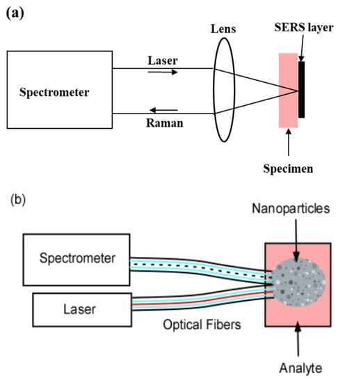
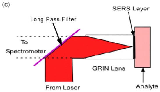
Figure 1.
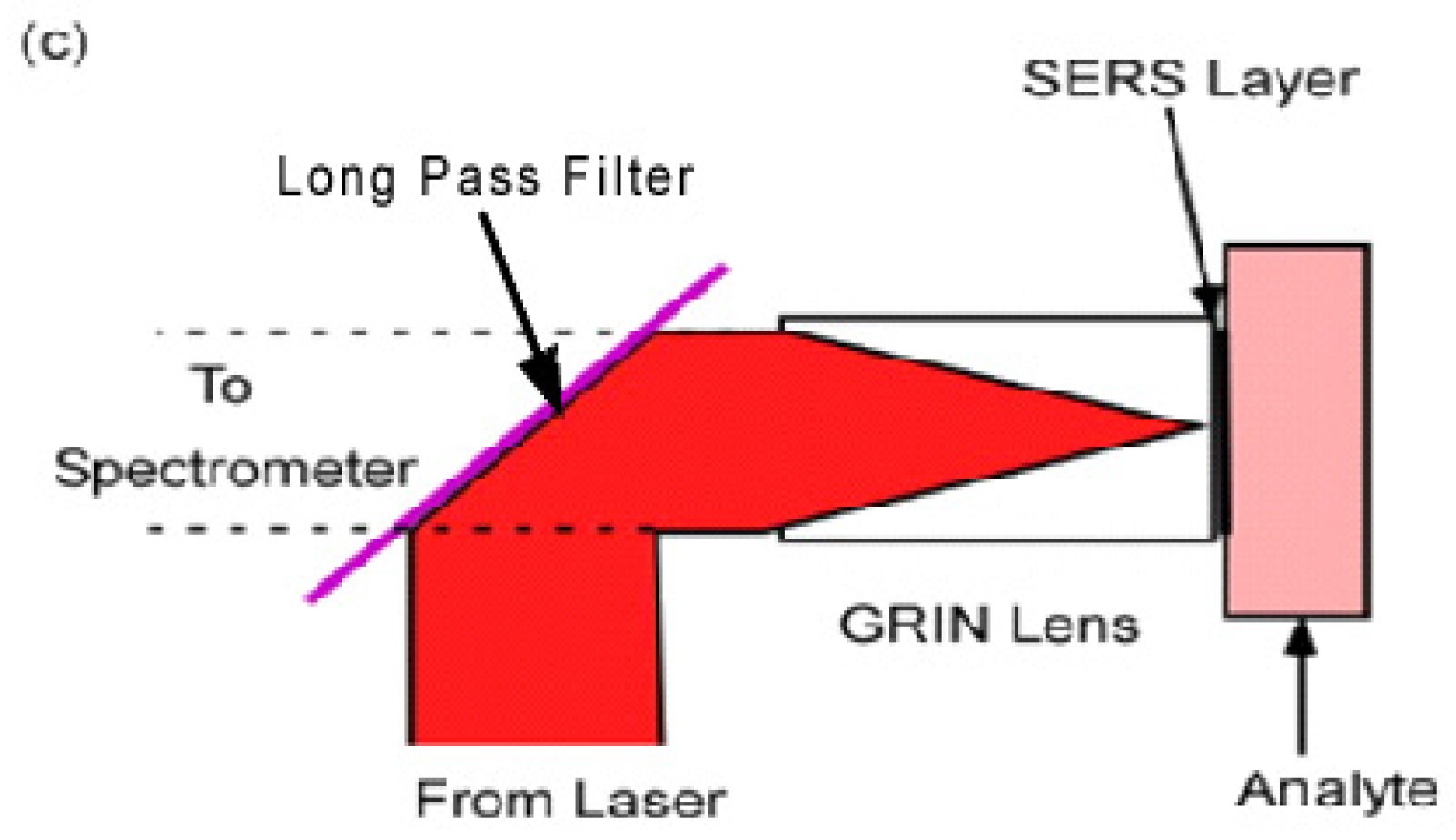
(a) In vitro sample configuration. The specimen is brought to the laser/spectrometer combination; (b) in vivo sample configuration. The SERS nanoparticles are injected as a cloud into the specimen; (c) GRIN lens probe. The SERS layer on the GRIN lens is brought to the surface or the interior of the specimen.
- (a)
- If the sample is inhomogeneous, adjacent areas may be compared with high spatial resolution.
- (b)
- The large solid angle sustained by the microscope objective collects a substantial fraction of the emitted isotropic Raman light.
- (c)
- Because the Raman light originates from a small area it is readily focused and transmitted through the spectrometer slit.
This is the most common approach for SERS [13,16,17].
For in vivo samples, e.g., partially transparent tissue in animals or humans, the incident radiation must be brought to the sample (Figure 1b,c). The most flexible way of achieving this is through an optical fiber probe. However, studies have shown that background signals generated within the fiber mask the returning Raman signals [5]. To exclude contamination by the Raman light generated within the fiber, light from the sample is returned to the spectrometer through a separate fiber or fibers [18] (Figure 1b). The nanometallic structures are distributed as a ‘cloud’ within the sample [19,20,21]. These structures may be spherical since spheres of the right diameter also concentrate the electric field of the incident radiation. However, the extended geometry of the cloud and the lack of the advantages provided by a lens seriously degrade the performance. In addition, each site studied requires a separate cloud, and nanoparticles left in the tissue may lead to cancer metastasis [22].
Previous work retained the advantages of the microscope objective by placing a Graded Index (GRIN) lens at the end of a remote probe [23]. The SERS layer was located in the back focal plane at the rear of the GRIN lens (Figure 1c). This is an ideal configuration for a SERS biological probe since the GRIN lens is narrow enough to be inserted into the specimen. In the arrangement in Figure 1c the incident laser light is reflected into the GRIN lens by a “long pass” interference filter. The longer wavelength Raman light is then transmitted through the filter to the spectrometer.
The SERS layer in Figure 1a,c may be achieved by lithographically patterning a flat metallic layer, or by chemically treating a suitable substrate so that metallic nanoparticles (NPs) self-assemble on its surface [24,25]. The exact dimensions are critical for optimal SERS performance [26,27,28,29]. The frictional forces inserting a SERS probe in biological applications require strong adhesion of the metallic nanoparticles so as not to dislodge the nanoparticles from the probe. This work describes an inexpensive method for the self-assembly and collection of nano-spheres to produce a SERS layer on a flat substrate. It also shows how their growth is controlled to the optimum diameter for Raman enhancement. Most important, it shows how they may be transferred and securely bonded to secondary surfaces, e.g., the rear surfaces of GRIN lenses. This is accomplished at low cost with inexpensive equipment, readily available materials, and with no chemical or lithographic steps. These may be critical concerns to laboratories faced with diminishing funding resources.
The choice of the SERS substrate, type, material and fabrication method depend on the specific application [25]. Although this work shows the suitability of the fabricated SERS substrates for both in vitro and bio-probe applications, the substrates are targeted towards remote sampling or SERS bio-probe applications. In comparison to existing SERS bio-probe applications, this work presents:
- (a)
- ERS substrates suitable for bio-probes or remote sampling without the disadvantages associated with injected clouds substrates and multiple fiber collection systems.
- (b)
- A low-cost alternative for SERS self-assembly fabrication method with no lithography or chemical synthesis.
2. Materials and Methods
2.1. Nanoparticles
Silver nanoparticles were obtained from an ink sold for ink-jet printers [30]. The specification for the ink states that the nanoparticles are 10 nm spheres in a 10% by weight suspension of hexane. In normal printer operation the droplets overlap each other but evaporate so quickly that there is minimal mixing of the nanoparticles. The nanoparticles then fuse to a planar structure of nearly constant thickness. In this work, additional hexane was added to dilute the suspension 1000×, resulting in an average separation between the nanoparticles in the hexane of 42 nm.
2.2. Imprinting
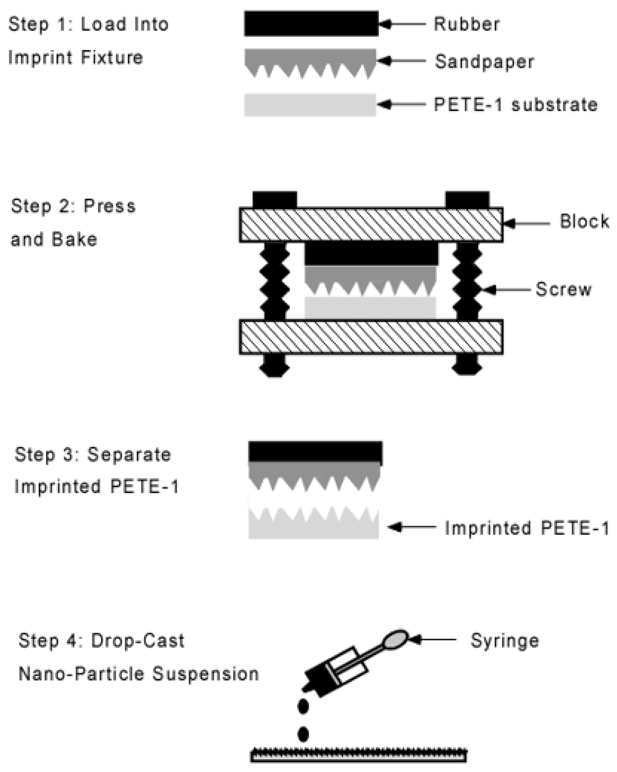
Substrates were prepared from 15 mm squares of 0.5 mm thick PETE-1 thermoplastic [31]. An imprinting step was used to form microscopic pits in the surface of the PETE-1. Costly lithographic processing was avoided by using fine grit sandpapers as a template. The imprint fixture had two blocks joined by two 1/4-20 screws, and a rubber pad to distribute the pressure (Figure 2). The screws were tightened by a torque wrench to 50 inch-pounds. This produced a force of 12,500 pounds, or a pressure of 250 MPa on the 15 mm substrates. The assembly was placed in a 35 °C oven [32] for 12 min. The low oven temperature was used to minimize the depth of the imprint.
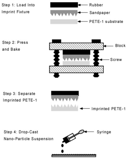
Figure 2.
Schematic flowchart of the imprint process. Portions enlarged for clarity.
2.3. Self Assembly
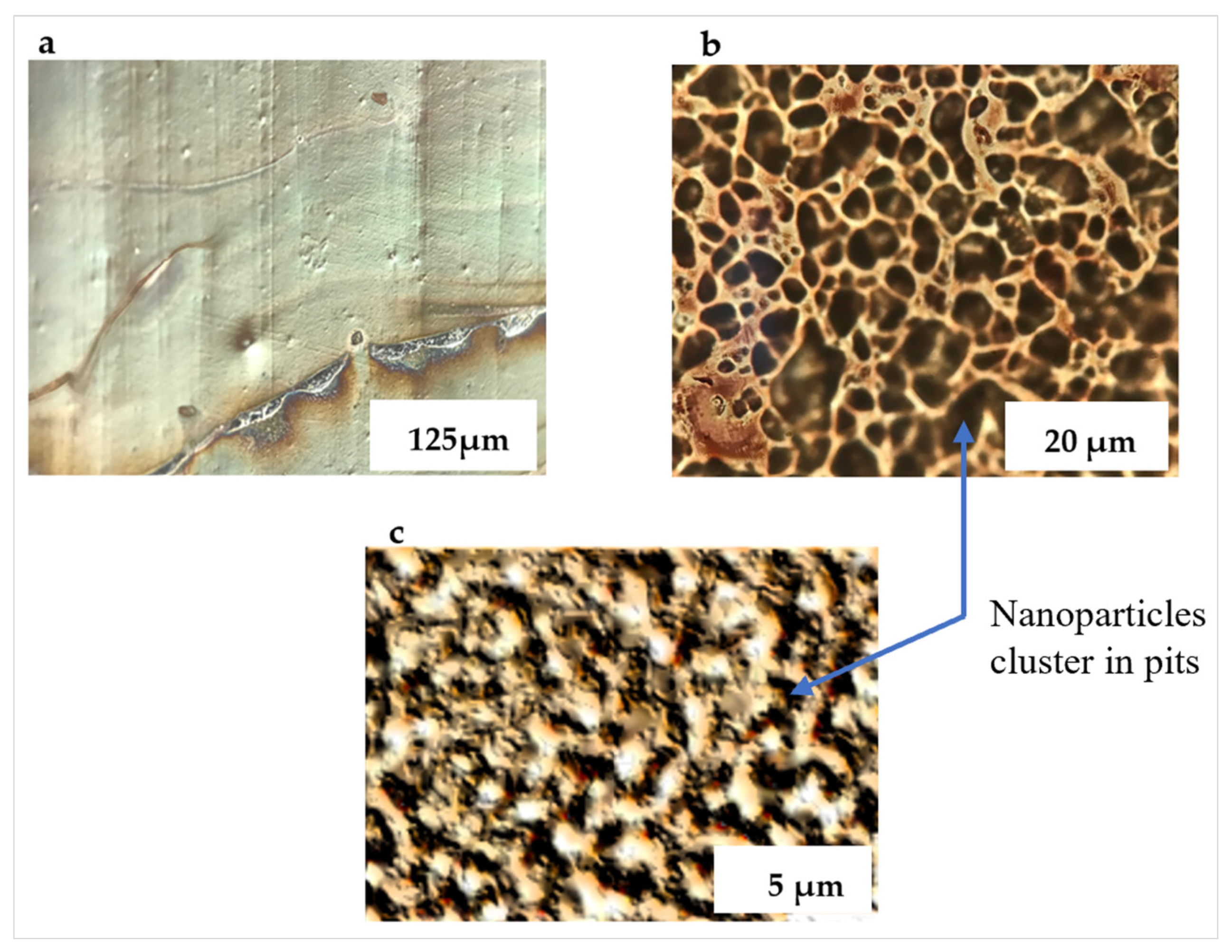
Drops of the diluted nanoparticle suspension were cast from a pipette onto the PETE-1 substrates (Figure 2, Step 4). Surface tension drove the hexane suspension into circles. On smooth PETE-1 surfaces, the nanoparticles followed the hexane as it evaporated, with the majority congregated in a narrow ring along the circumference (Figure 3a). However, more uniform nanoparticle distributions were obtained with the imprinted substrates. As the hexane suspension spread towards the circumference of a circle, most of it became trapped in pits in the surface along the way. The volume of these pits depended on the oven temperature and the roughness, or grit, of the sandpaper. Figure 3b,c show that 1µm grit sandpaper isolated smaller volumes of the suspension, and therefore smaller numbers of nanoparticles than the 6µm grit sandpaper.
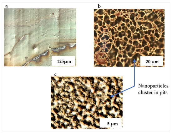
Figure 3.
Optical micrographs of deposited nanoparticle suspension. (a) Ag nanoparticles on non-imprinted PETE congregate along the rim of a circle; (b) isolated islands of Ag nanoparticles form on 6µm grit imprinted PETE; (c) much smaller islands of Ag nanoparticles form on 1 µm grit imprinted PETE.
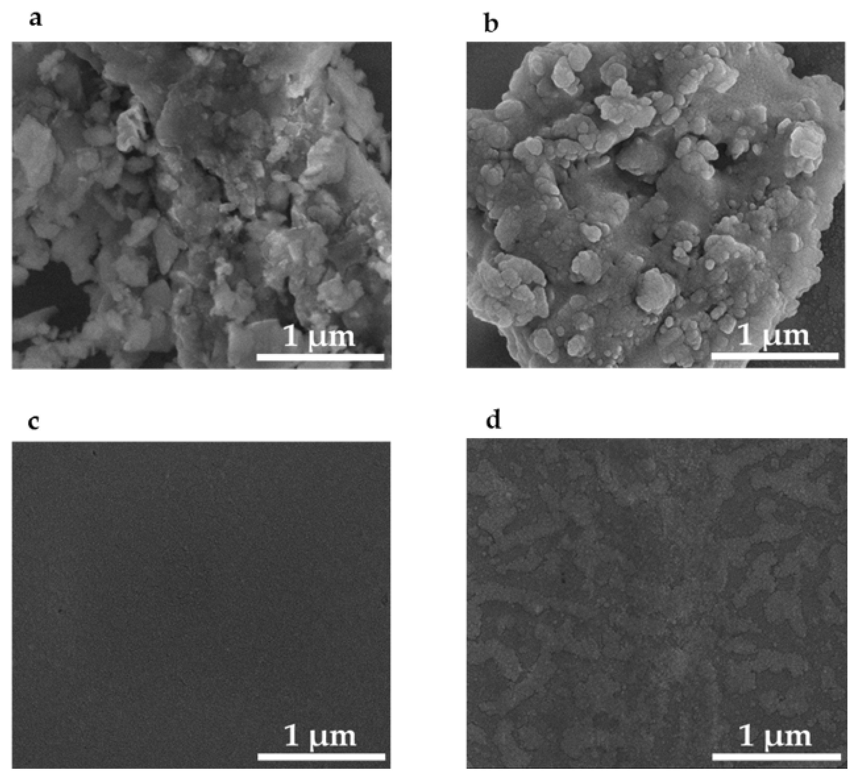
Figure 4a is an SEM image of the 1 µm grit sandpaper. Figure 4b is an SEM of the imprinted PETE-1 containing drop-cast silver nano-spheres. As the hexane evaporated, the nano-spheres were formed by nearby nanoparticles adhering to each other and self-assembling into larger spheres. The size of the spheres depended on the number of nanoparticles available. Casting multiple drops provided fresh nanoparticles and increased the size of the spheres. Three consecutive drops of the diluted suspension of Ag in hexane on PETE imprinted with 1 µm grit sandpaper grew spheres of about 80 nm diameter and produced optimum SERS result.
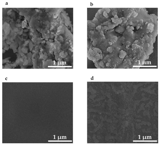
Figure 4.
Scanning electron micrographs of: (a) 1 µm grit sandpaper template; (b) silver nanoparticles assembled in the pits of PETE-1 thermoplastic imprinted with 1 μm sandpaper; (c) non-imprinted and featureless PETE-1; (d) non-imprinted PETE-1 with few if any nanoparticles after drop-casting of the nanoparticle suspension.
In contrast no structure can be seen in an SEM of non-imprinted PETE-1 (Figure 4c), and few if any nanoparticles can be found after the nanoparticle suspension is cast on non-imprinted PETE-1 (Figure 4d). The comparison between Figure 4b,d shows the critical role of the pits in the imprinted PETE-1 to trap small volumes of the suspension.
2.4. Transfer to Different Substrates
The SERS layers described here often need to be transferred to a new substrate; for example, as part of a complex instrument. This is particularly true in a biological probe for the following reasons:
- (a)
- The nanospheres must be securely attached so they do not fall off and remain in the tissue.
- (b)
- Transmission to the spectrometer is poor without a lens to collect and collimate the Raman light to focus it on the spectrometer slit.
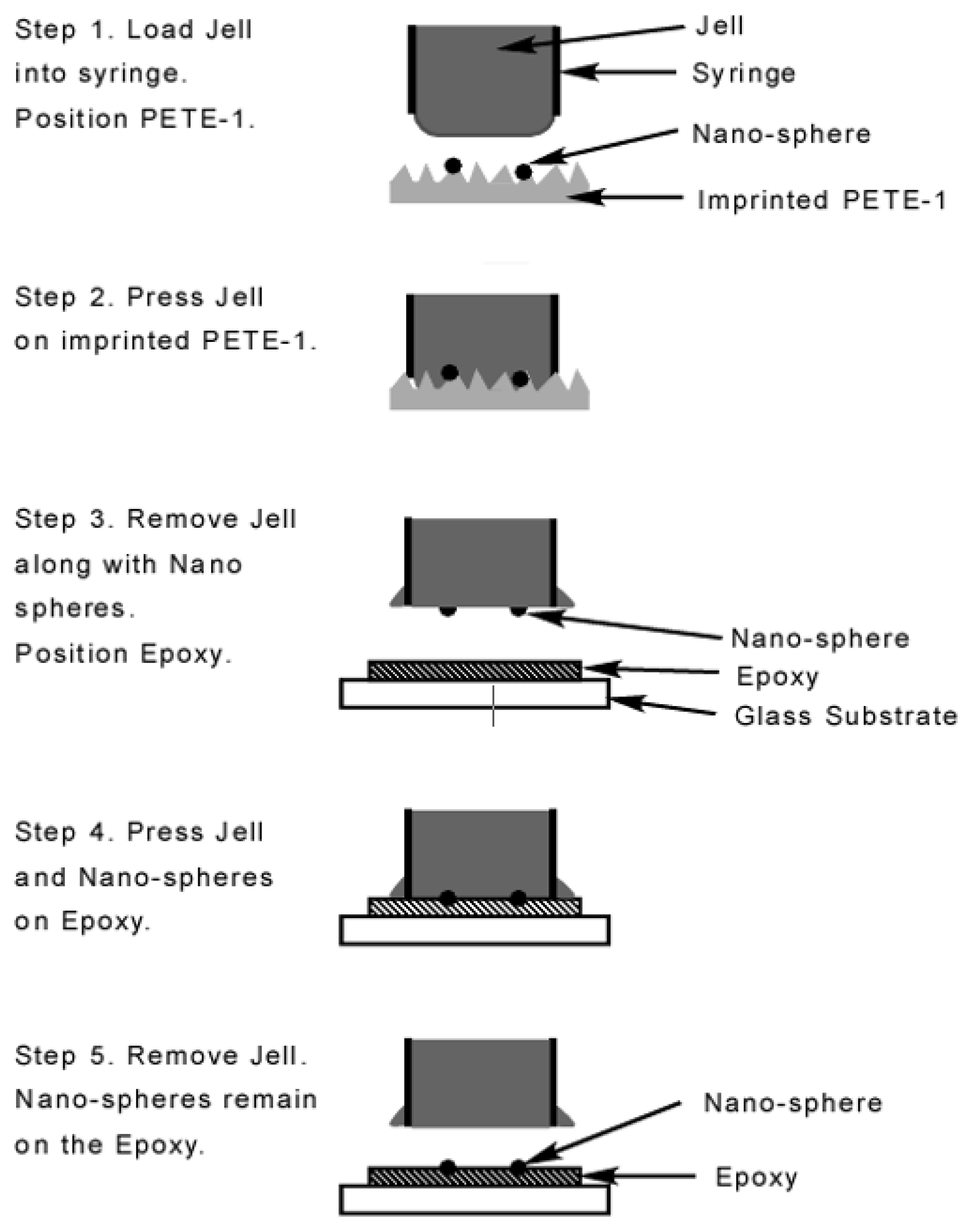
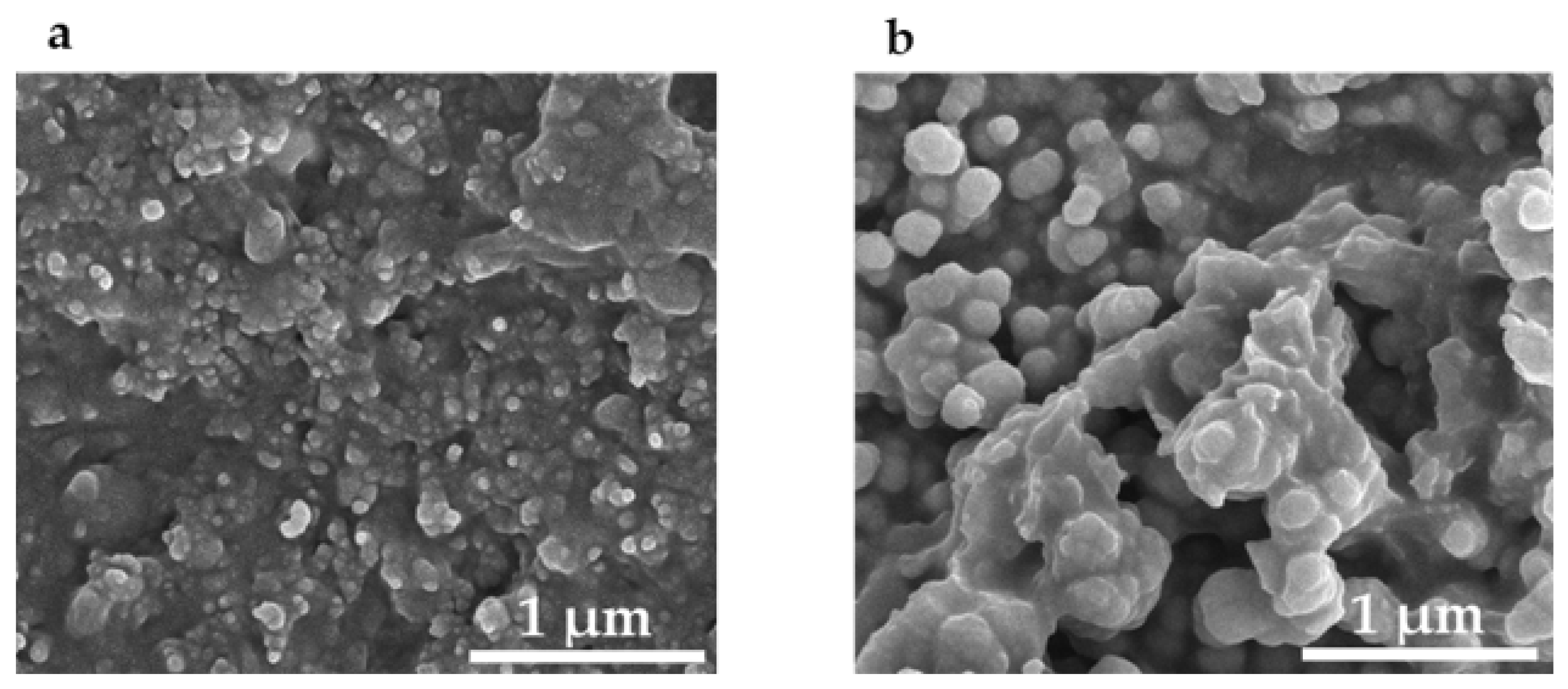
The transfer process used a widely available jell [33] as a sacrificial layer. The jell protruded slightly from a syringe which was gently tapped against the thermoplastic (Figure 5). Next, a thin layer of quick setting epoxy [34], was spread on a cover slip, pressed against a flat sheet of “non-stick” silicone rubber, and allowed to partially harden. This procedure was necessary to prevent the epoxy from flowing around and encapsulating the nanoparticles. Then the syringe was pressed against the surface of the epoxy and the jell was forced out against it. The fixture was left for 24 h to fully cure. The syringe was removed, taking along the Jell and leaving the nanospheres securely epoxied to the cover slip. Multiple taps of the jell to the PETE transferred more nanoparticles, which then self-assembled into larger spheres. Two taps collected spheres of about 80 nm diameter (Figure 6a) which were optimum for SERS applications as shown in the results section. Ten taps produced spheres as large as 175 nm diameter (Figure 6b) that weren’t suitable for SERS applications.
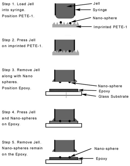
Figure 5.
Schematic flowchart of the transfer process. Portions enlarged for clarity.
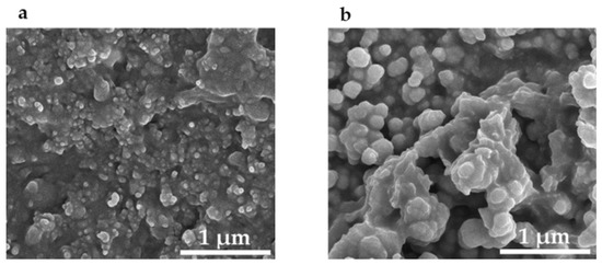
Figure 6.
Scanning electron micrographs of silver nanospheres transferred to epoxy on a glass cover slip. The nanoparticles are held in the pits formed by the sandpaper. (a) Two taps; (b) ten taps.
2.5. Measurements and Characterization
Figure 3b,c was taken with a 100× objective on an Olympus U-SPT Optical Microscope Model BX60F5 coupled to an iPhone camera [35]. The Scanning Electron Microscope images were obtained with a JSM-6610 LV Scanning Electron Microscope.
SERS measurements were obtained with a HORIBA confocal Labram Raman spectrometer equipped with 50×, 0.55 NA microscope objective and a 30 mW, 633 nm HeNe excitation laser. The exposure time, scan time and resolution are 60 s, 60 s and 20 cm−1, respectively. Rhodamine 6G solution was prepared from powdered Rhodamine dye [36].
3. Results
This study describes the self-assembly and collection of nanospheres on an imprinted plane and the control of their growth to the optimum 80 nm diameter for Raman enhancement. The growth was controlled at several stages by selecting the volume and concentration of seed 10 nm silver spheres in isolated hexane compartments.
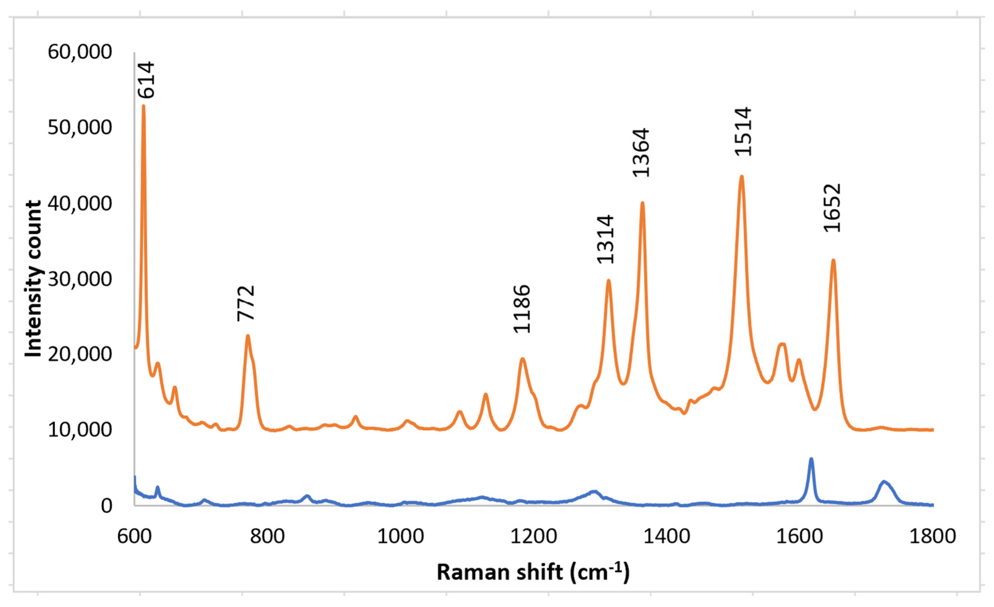
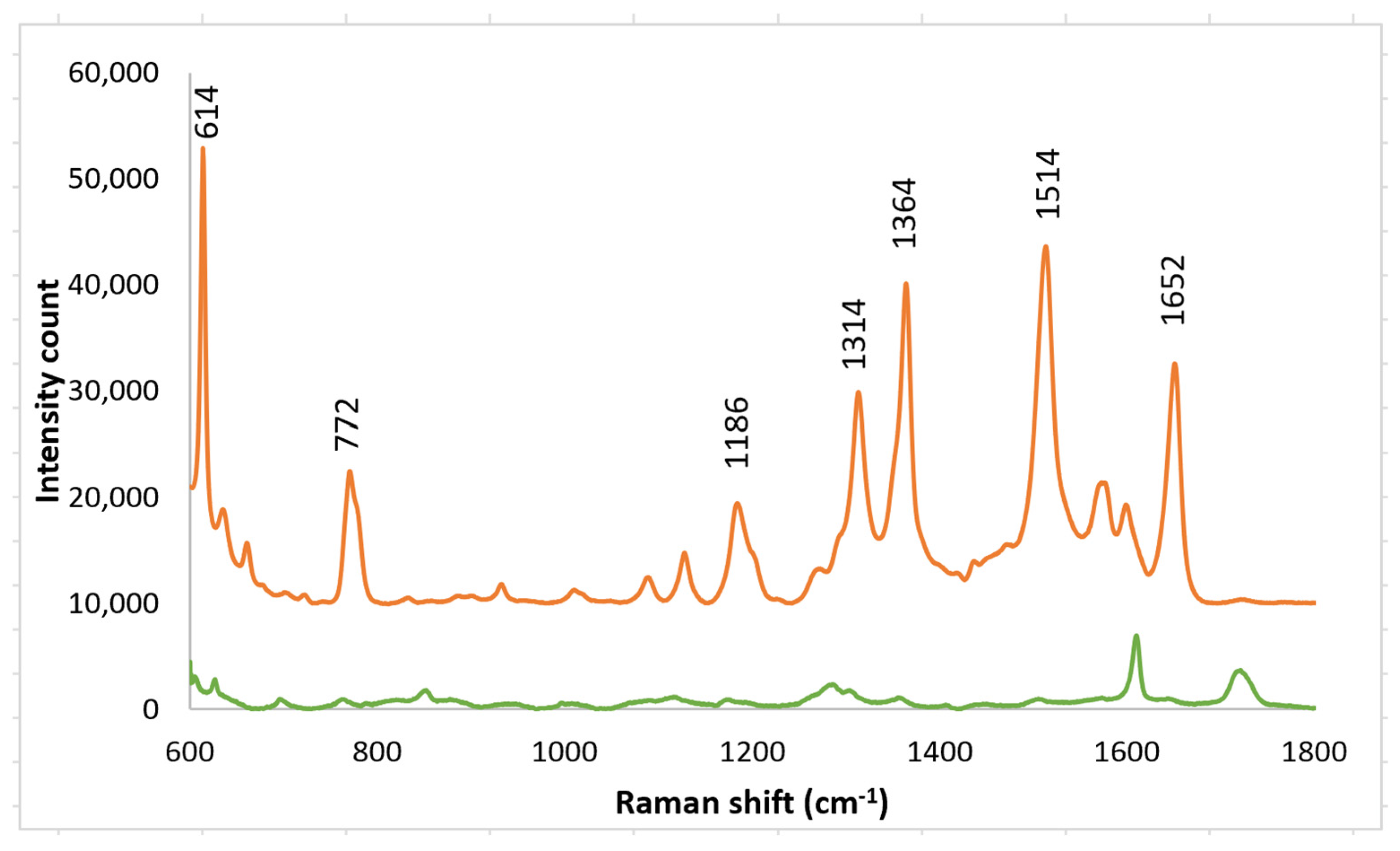
Solutions of Rhodamine 6G (R6G) were used to test the enhancement of the SERS layers. R6G was used; it is one of the dyes that has well-established Raman vibrational bands. Raman spectra were obtained with SERS layers both on the imprinted PETE-1 substrate (Figure 1a) suitable for in vitro samples, and after bonding to epoxy on a cover slip as needed for SERS bio-probe (Figure 1c). Rhodamine 6G Raman spectral peaks were observed at their well-known Raman bands of 614 cm−1, 772 cm−1, 1186 cm−1, 1134 cm−1, 1364 cm−1, 1514 cm−1 and 1652 cm−1 [36,37,38,39]. The 614 cm−1 band accounts for the C-C-C in-plane bending; the 772 cm−1 band accounts for the C-H out-plane bending; the 1186 cm−1 band accounts for the C-H in-plane bending; the 1134 cm−1 band accounts for the C=C stretching; the 1364 cm−1, 1514 cm−1 and the 1652 cm−1 bands account for the C-C stretching vibrational modes [40]. With neither SERS layer present, a Horiba Raman spectrometer detected no Raman spectra from a 1 mm solution of R6G.
3.1. PETE-1 Substrate
A solution of R6G was placed on a SERS substrate made by nano-sphere deposition on an imprinted PETE-1 substrate. A strong Raman signal was obtained from a 1 mm solution of R6G (Figure 7, top trace) using the arrangement in Figure 1a. The background spectrum from the PETE-1 SERS substrate was also obtained with no R6G present (Figure 7, bottom trace). The small background is readily separated from the R6G spectrum. We believe the surface-enhanced Raman hot spots are caused by plasmonic focusing of the incident radiation along the surface of the silver nano-spheres, with a resonance between the incident wavelength and the optimal spherical diameter, but without any chemical bonding of the R6G.
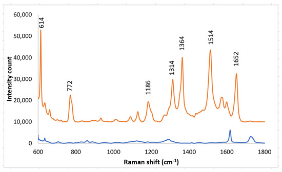
Figure 7.
Top trace, Raman spectrum of 1 mm R6G after drop casting silver nano-sphere suspension on imprinted PETE-1. Bottom trace, Background spectra obtained after drop casting silver nano-sphere suspension on an imprinted PETE-1 SERS with no R6G present.
Spectra were also taken in which the PETE-1 substrate was not imprinted (Figure 8). In this case only a background signal, largely from the PETE-1, was obtained. This demonstrates the important role imprinting plays in generating the R6G Raman signal.
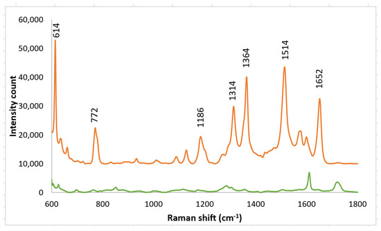
Figure 8.
Top trace, 1 mm R6G spectra after drop casting nano-sphere suspension on imprinted PETE-1. Bottom trace, 1 mmol R6G spectra after drop casting nano-sphere suspension on PETE-1 that was not imprinted.
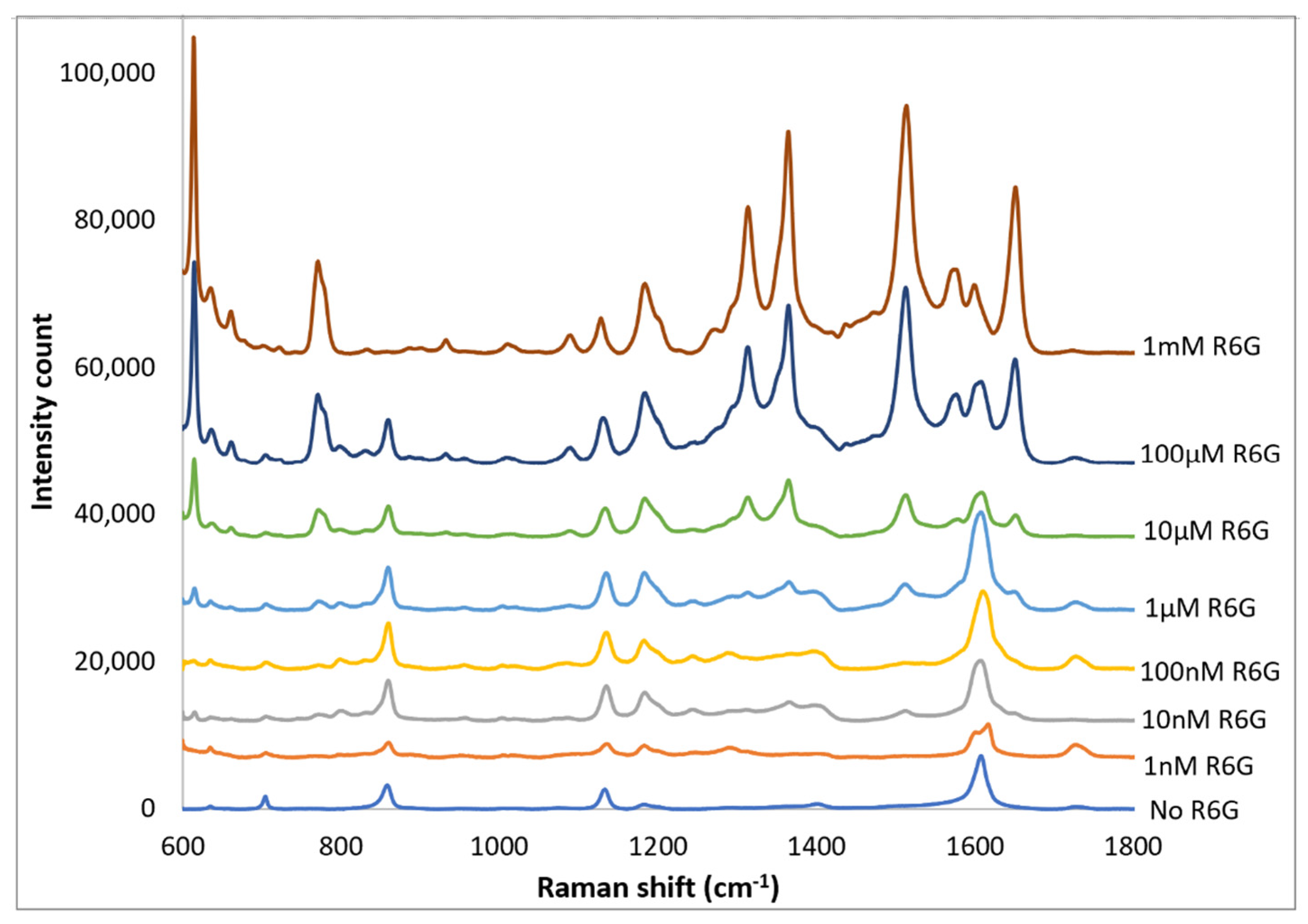
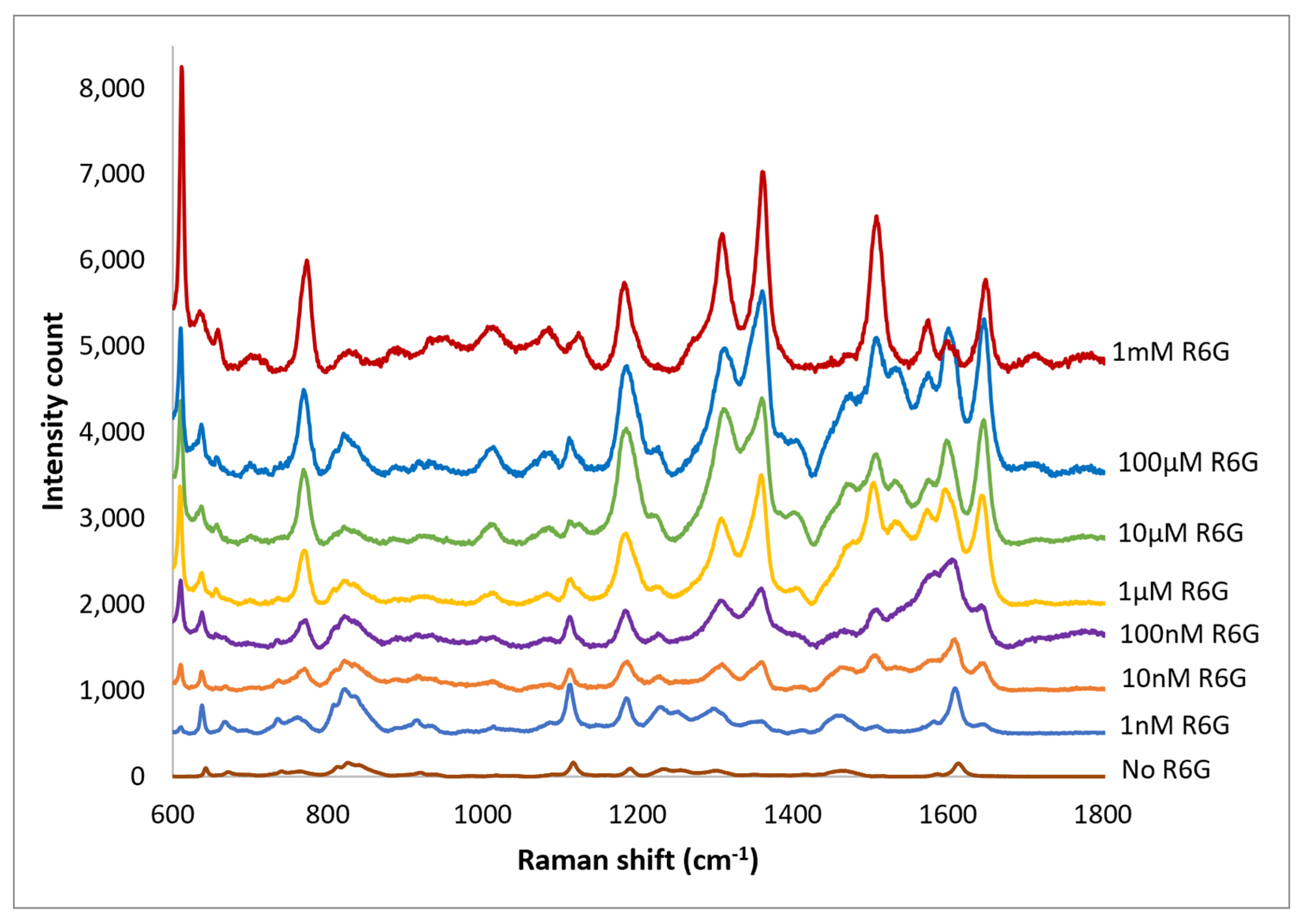
Spectra of R6G solutions on PETE-1 substrates with concentrations ranging from 1 nm to 1 mm are shown in Figure 9. The background spectra without R6G are also shown. Although the background is more significant at the lower concentrations, individual R6G peaks can be identified down to the lowest concentration of 1 nmol. Figure 9 also shows that the intensity of the background signal peaks, such as the one around 1600 cm−1, reduces as the intensity of R6G Raman peaks increase with increasing concentrations.
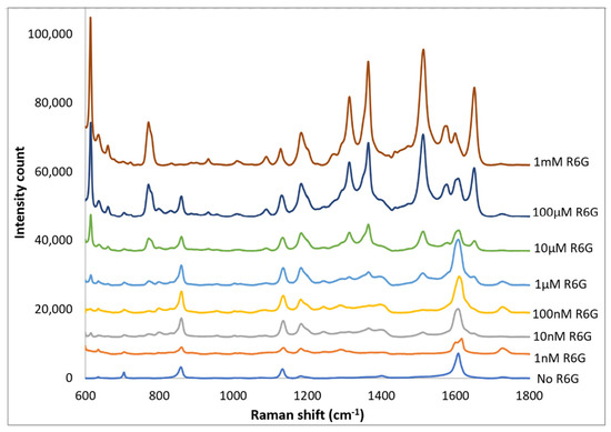
Figure 9.
Top traces, Raman spectrum of 1 nm to 1 mm concentrations of R6G obtained after drop-casting silver nano-sphere suspension on imprinted PETE-1. Bottom trace, no R6G. For clarity the spectra have been offset vertically.
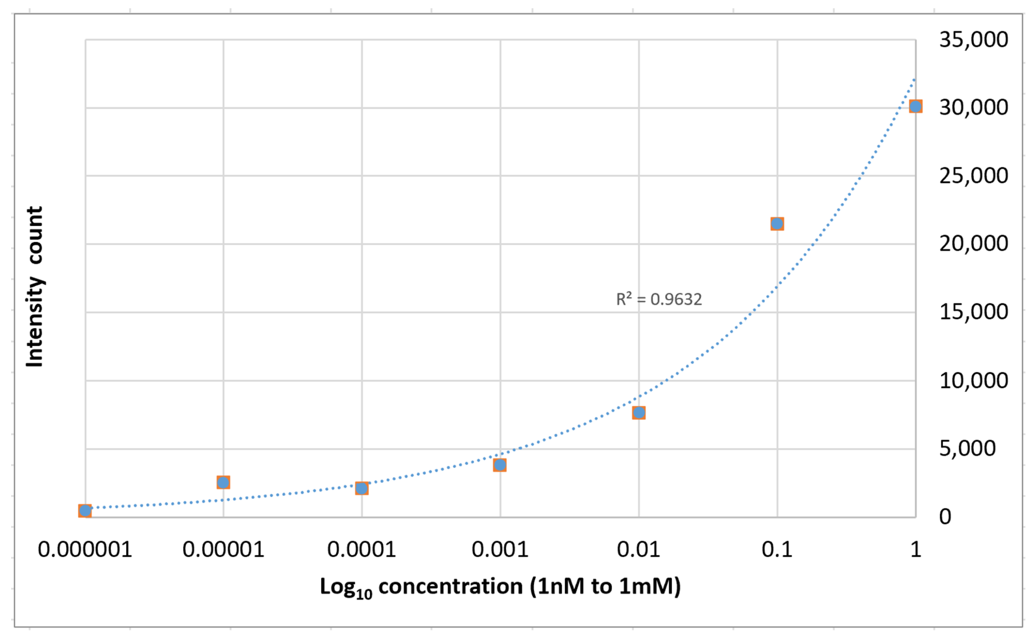
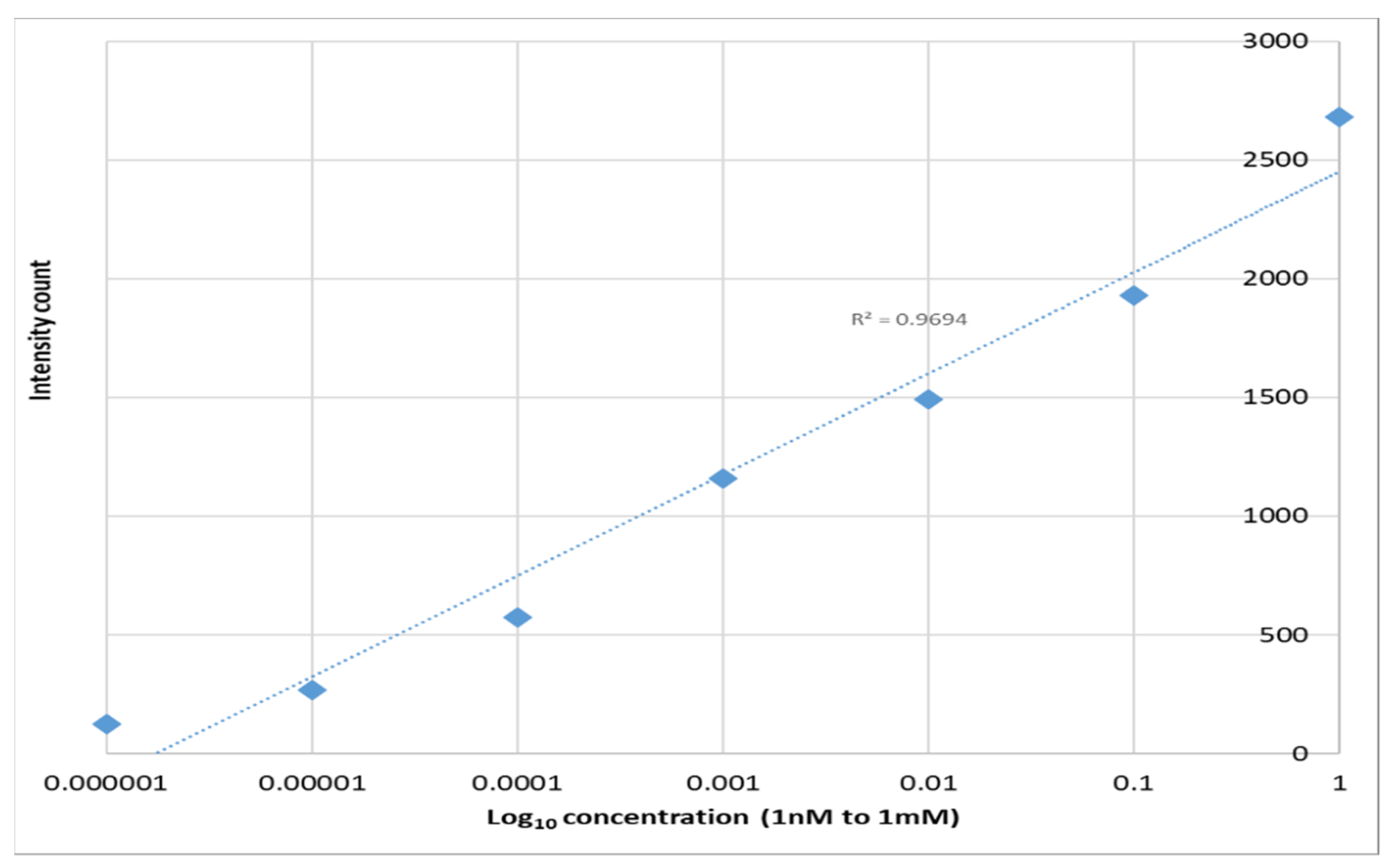
The relative strength of the enhanced spectra as measured at the 1364 cm−1 Raman peak is given as a function of the concentration of the solution is shown in Figure 10. The average enhancement factor of the SERS substrates was estimated to be 1.6 × 10⁴ using the following equation:
where and are highest and lowest concentrations of the R6G solution respectively; and and are their intensities measured at the same Raman band.
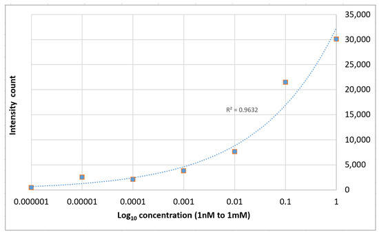
Figure 10.
1364 cm−1 Raman signal strength vs. Rhodamine 6G concentration on PETE-1 SERS.
3.2. Epoxy Substrate
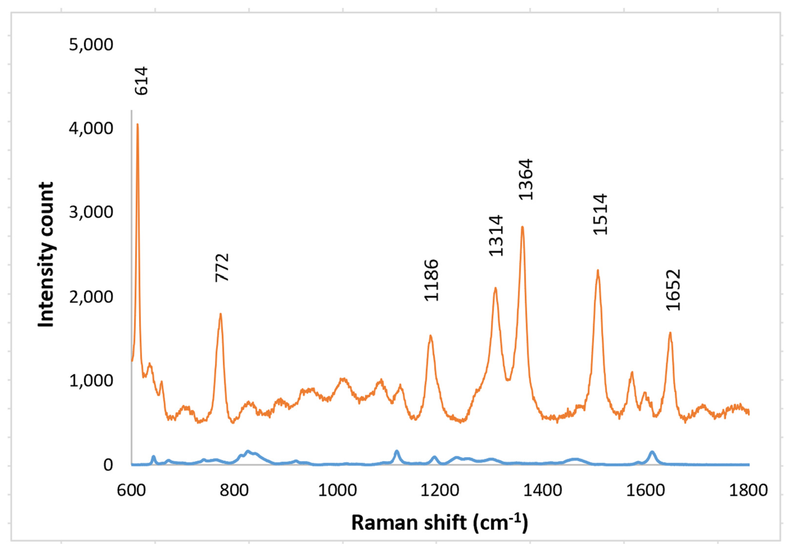
For biological probes the nano-spheres must be securely bonded to a substrate, for example to a GRIN lens. Therefore, Raman spectra were obtained with solutions of R6G on SERS layers epoxied to clear substrates. A small background from the epoxy was observed with no R6G present but it was readily separated from the R6G spectrum (Figure 11). Spectra were obtained R6G concentrations from 1 nm to 1 mm (Figure 12). As with the PETE-1 substrates, individual R6G peaks can be identified down to the lowest concentration of 1 nM. Figure 12 shows that the intensity of the background signal peaks, such as the one around 1600 cm−1, reduces as the intensity of R6G Raman peaks increase with increasing concentrations. The relative strength of the enhanced spectra as a function of the concentration of the solution is shown in Figure 13, again as expected for SERS enhancement.
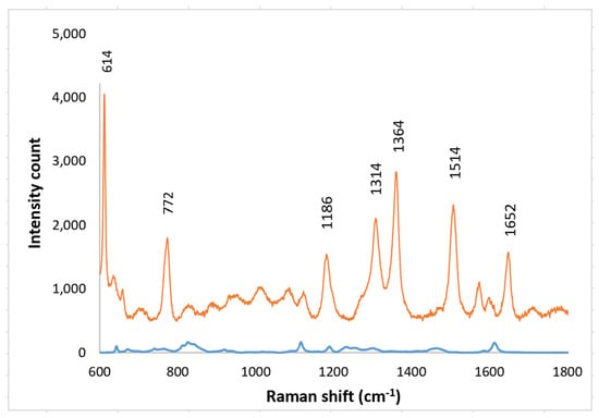
Figure 11.
Top trace, Raman spectrum of 1 mm R6G obtained after transferring nanospheres to epoxy on glass. Bottom trace, Background spectra from the transferred nanospheres to epoxy on glass with no R6G present.
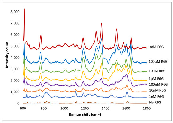
Figure 12.
Top traces, Raman spectrum of 1 nm to 1 mm concentrations of R6G obtained after transferring silver nano-sphere suspension to epoxy on glass. Bottom trace, no R6G. For clarity, the spectra have been offset vertically.
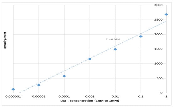
Figure 13.
1364 cm−1 Raman signal strength vs. Rhodamine 6G concentration on epoxy SERS.
4. Discussion
The developed SERS substrate based on silver nanoparticle assembled over imprinted plastic can be used for portable or in vitro analysis schemes. The transferable nature of the SERS substrate also makes it a candidate for remote sampling or in vivo SERS applications. A comparative review of similar SERS substrates that were developed for bio-probe or re applications is summarized in Table 1.

Table 1.
Summary of different SERS substrates reported for bio-probe applications.
The use of nanoparticles of gold or silver is the more common approach. Planar SERS substrates based on silver or gold layer over nanospheres [41,43], and silver coated microneedles have also been employed in implantation-based bio-probe schemes [46]. In the case of nanoparticle-based approaches, the nanoparticles are either combined with the analyte in vitro [44] or injected into analyte tissue in vivo [42,45]. The limitations inherent to using such free nanoparticle clouds have been discussed earlier in Section 1 of this paper. When designing nanoparticle-based SERS sensors for potential in vivo applications, it is critical that the whole sensor stay intact in vivo to produce the desired signal, after which the nanoparticles should be expelled from the body [47]. Nanoparticle clouds injected into tissue are well separated from the collecting optics and consequently only a small fraction of the Raman light is collected. The advantage of a defined nanoparticle location is that the incident light from a laser can be focused to a small spot, and a large fraction of the Raman light generated can be collected by the same or a confocal lens. It is well known that the strength of the Raman signal is proportional to the square of the numerical aperture (NA) of the collecting lens. In this context, the SERS substrate transferred to a GRIN lens as described here can potentially address these limitations related to the randomly dispersed nanoparticle clouds.
The SERS substrates developed in this work are inexpensive. This cost was approximated based on the cost of the materials used in the fabrication. The cost of a 1.5 cm2 PETE is much less than USD 0.01. 0.15 mL (3 drops) of the diluted Ag ink and hexane used on each 1 cm2 substrate cost less than USD 0.01. The cost of the sandpaper was hard to estimate as a single 1 cm2 piece was used repeatedly without apparent degradation. Additionally, there is no use of expensive equipment or processes during fabrication. Consequently, the developed SERS substrate are very low cost, much less than USD 0.01 per 1.5 cm2 active area. Table 2 shows compares the R6G SERS Enhancement factor (EF), detection limit, and cost per active area of the substates in this work with other literatures.

Table 2.
Comparison of various low-cost substrates used to detect R6G.
The approach described here shows that strong Raman signals may be obtained with minimal equipment and with no chemical or lithographic steps. These may be critical concerns to laboratories faced with diminishing funding resources. While developed for Raman spectroscopy, the wide area low-cost imprint technique may have other applications as well, for example as anti-reflection coatings for solar cell arrays. However, our future work will transfer the SERS layers to the back focal planes of GRIN lenses, forming a rugged probe which focuses the incident light and effectively collects the Raman light from biological probes as shown in Figure 1c.
5. Conclusions
This paper describes a facile method of producing a SERS layer on an imprinted thermoplastic. Surfaces of thermoplastic were imprinted using sandpapers of known grit size. SERS layers were made by self-assembly of silver nanoparticles on the imprinted thermoplastic. Using this SERS substrate, Raman spectra from R6G dye were detected at concentrations as low as 1 nM. This SERS substrate has potential usage in a wide range of portable Raman sensing applications. For potential bio-probe or remote applications, a transferable SERS substrate was also demonstrated by transferring the assembled silver nanoparticles from the imprinted plastic onto an epoxy support layer. The transferable SERS substrate was used to detect R6G dye spectra at concentrations as low as 1 nmol. The fabrication of these SERS substrates does not require expensive equipment or processes. Consequently, the developed SERS substrates are useful for applications needing low-cost SERS substrates.
Author Contributions
Conceptualization, L.J., N.K., B.A. and M.F.; methodology, M.F., B.A. and D.C.; software, B.A. and D.B.; validation, B.A. and M.F.; formal analysis, B.A., M.F. and L.J.; investigation, B.A.; resources, M.F.; data curation, B.A. and M.F.; writing—original draft preparation, B.A; writing—review and editing, B.A., M.F., L.J. and N.K.; supervision, M.F.; project administration, M.F.; funding acquisition D.C. All authors have read and agreed to the published version of the manuscript.
Funding
The SEM characterization in this work was funded by the Louisiana State University Shared Instrumentation Facility (LSU SIF).
Institutional Review Board Statement
Not applicable.
Informed Consent Statement
Not applicable.
Acknowledgments
We would like to acknowledge Chris O’loughlin of the Louisiana State University Electronic Materials and Devices laboratory for his technical support.
Conflicts of Interest
The authors declare no conflict of interest.
References
- Eberhardt, K.; Stiebing, C.; Matthäus, C.; Schmitt, M.; Popp, J. Advantages and limitations of Raman spectroscopy for molecular diagnostics: An update. Expert Rev. Mol. Diagn. 2015, 15, 773–787. [Google Scholar] [CrossRef] [PubMed]
- Vbaková, H. A powerful tool for material identification: Raman spectroscopy. Int. J. Math. Model. Methods Appl. Sci. 2011, 5, 1205–1212. [Google Scholar]
- Kneipp, K.; Kneipp, H.; Itzkan, I.; Dasari, R.R.; Feld, M.S. Ultrasensitive Chemical Analysis by Raman Spectroscopy. Chem. Rev. 1999, 99, 2957–2976. [Google Scholar] [CrossRef] [PubMed]
- Zhao, J.; Zeng, H.; Kalia, S.; Lui, H. Using Raman Spectroscopy to Detect and Diagnose Skin Cancer In Vivo. Dermatol. Clin. 2017, 35, 495–504. [Google Scholar] [CrossRef]
- Taketani, A.; Hariyani, R.; Ishigaki, M.; Andriana, B.B.; Sato, H. Raman endoscopy for the in situ investigation of advancing colorectal tumors in live model mice. Analyst 2013, 138, 4183–4190. [Google Scholar] [CrossRef]
- De Abajo, F.J.G. Colloquium: Light scattering by particle and hole arrays. Rev. Mod. Phys. 2007, 79, 1267–1290. [Google Scholar] [CrossRef] [Green Version]
- Moskovits, M. Surface-enhanced spectroscopy. Rev. Mod. Phys. 1985, 57, 783–826. [Google Scholar] [CrossRef]
- Murphy, C.J.; Gole, A.M.; Stone, J.W.; Sisco, P.N.; Alkilany, A.M.; Goldsmith, E.C.; Baxter, S.C. Gold Nanoparticles in Biology: Beyond Toxicity to Cellular Imaging. Acc. Chem. Res. 2008, 41, 1721–1730. [Google Scholar] [CrossRef]
- Sharma, B.; Cardinal, M.F.; Kleinman, S.L.; Greeneltch, N.G.; Frontiera, R.R.; Blaber, M.G.; Schatz, G.C.; Van Duyne, R.P. High-performance SERS substrates: Advances and challenges. MRS Bull. 2013, 38, 615–624. [Google Scholar] [CrossRef] [Green Version]
- Plaickner, J.; Speiser, E.; Chandola, S.; Esser, N.; Singh, D.K. Adsorption of toluene-3,4-dithiol on silver islands investigated by surface-enhanced Raman spectroscopy. J. Raman Spectrosc. 2020, 51, 788–794. [Google Scholar] [CrossRef]
- Kaushik, V.; Kagdada, H.L.; Singh, D.K.; Pathak, S. Enhancement of SERS effect in Graphene-Silver hybrids. Appl. Surf. Sci. 2022, 574, 151724. [Google Scholar] [CrossRef]
- Singh, D.; Ganbold, E.-O.; Cho, E.-M.; Cho, K.-H.; Kim, D.; Choo, J.; Kim, S.; Lee, C.M.; Yang, S.I.; Joo, S.-W. Detection of the mycotoxin citrinin using silver substrates and Raman spectroscopy. J. Hazard. Mater. 2014, 265, 89–95. [Google Scholar] [CrossRef] [PubMed]
- Stiles, P.L.; Dieringer, J.A.; Shah, N.C.; Van Duyne, R.P. Surface-enhanced Raman spectroscopy. Annu. Rev. Anal. Chem. 2008, 1, 601–626. [Google Scholar] [CrossRef] [PubMed] [Green Version]
- Wei, H.; Xu, H. Hot spots in different metal nanostructures for plasmon-enhanced Raman spectroscopy. Nanoscale 2013, 5, 10794–10805. [Google Scholar] [CrossRef]
- Zhang, Y.-J.; Chen, S.; Radjenovic, P.; Bodappa, N.; Zhang, H.; Yang, Z.-L.; Tian, Z.-Q.; Li, J.-F. Probing the Location of 3D Hot Spots in Gold Nanoparticle Films Using Surface-Enhanced Raman Spectroscopy. Anal. Chem. 2019, 91, 5316–5322. [Google Scholar] [CrossRef]
- Snitka, V.; Batiuskaite, D.; Bruzaite, I.; Lafont, U.; Butenko, Y.; Semprimoschnig, C. Surface-enhanced Raman scattering sensors for biomedical and molecular detection applications in space. CEAS Space J. 2021, 13, 509–520. [Google Scholar] [CrossRef]
- Pan, J.; Shao, X.; Zhu, Y.; Dong, B.; Wang, Y.; Kang, X.; Chen, N.; Chen, Z.; Liu, S.; Xue, W. Surface-enhanced Raman spectroscopy before radical prostatectomy predicts biochemical recurrence better than CAPRA-S. Int. J. Nanomed. 2019, 14, 431–440. [Google Scholar] [CrossRef] [Green Version]
- Motz, J.T.; Hunter, M.; Galindo, L.H.; Gardecki, J.A.; Kramer, J.R.; Dasari, R.R.; Feld, M.S. Optical Fiber Probe for Biomedical Raman Spectroscopy. Appl. Opt. 2004, 43, 542–554. [Google Scholar] [CrossRef]
- Shi, C.; Zhang, Y.; Gu, C.; Chen, B.; Seballos, L.; Olson, T.; Zhang, J.Z. Molecular Fiber Sensors Based on Surface Enhanced Raman Scattering (SERS). J. Nanosci. Nanotechnol. 2009, 9, 2234–2246. [Google Scholar] [CrossRef]
- Dhakal, S.; Chao, K.; Huang, Q.; Kim, M.; Schmidt, W.; Qin, J.; Broadhurst, C.L. A Simple Surface-Enhanced Raman Spectroscopic Method for on-Site Screening of Tetracycline Residue in Whole Milk. Sensors 2018, 18, 424. [Google Scholar] [CrossRef] [Green Version]
- Zavaleta, C.L.; Smith, B.R.; Walton, I.; Doering, W.; Davis, G.; Shojaei, B.; Natan, M.J.; Gambhir, S.S. Multiplexed imaging of surface enhanced Raman scattering nanotags in living mice using noninvasive Raman spectroscopy. Proc. Natl. Acad. Sci. USA 2009, 106, 13511–13516. [Google Scholar] [CrossRef] [PubMed] [Green Version]
- Peng, F.; Setyawati, M.I.; Tee, J.K.; Ding, X.; Wang, J.; Nga, M.E.; Ho, H.K.; Leong, D.T. Nanoparticles promote in vivo breast cancer cell intravasation and extravasation by inducing endothelial leakiness. Nat. Nanotechnol. 2019, 14, 279–286. [Google Scholar] [CrossRef] [PubMed]
- Basu, S.; Hou, H.; Biswas, D.; Lopez, M.; Feldman, M.; Daniels-Race, T.; Mathis, J.M. Single fiber surface enhanced Raman scattering probe. J. Vac. Sci. Technol. B Nanotechnol. Microelectron. Mater. Process. Meas. Phenom. 2017, 35, 06GF01. [Google Scholar] [CrossRef]
- Abu Hatab, N.A.; Oran, J.M.; Sepaniak, M.J. Surface-Enhanced Raman Spectroscopy Substrates Created via Electron Beam Lithography and Nanotransfer Printing. ACS Nano 2008, 2, 377–385. [Google Scholar] [CrossRef] [PubMed]
- Langer, J.; de Aberasturi, D.J.; Aizpurua, J.; Alvarez-Puebla, R.A.; Auguié, B.; Baumberg, J.J.; Bazan, G.C.; Bell, S.E.J.; Boisen, A.; Brolo, , A.G.; et al. Present and Future of Surface-Enhanced Raman Scattering. ACS Nano 2020, 14, 28–117. [Google Scholar] [CrossRef] [Green Version]
- Boca, C.S.; Farcau, C.; Astilean, S. The study of Raman enhancement efficiency as function of nanoparticle size and shape. Nucl. Instrum. Methods Phys. Res. Sect. B Beam Interact. Mater. Atoms. 2009, 267, 406–410. [Google Scholar] [CrossRef]
- Hong, S.; Li, X. Optimal Size of Gold Nanoparticles for Surface-Enhanced Raman Spectroscopy under Different Conditions. J. Nanomater. 2013, 2013, 40. [Google Scholar] [CrossRef]
- Seney, C.S.; Gutzman, B.M.; Goddard, R.H. Correlation of Size and Surface-Enhanced Raman Scattering Activity of Optical and Spectroscopic Properties for Silver Nanoparticles. J. Phys. Chem. C 2008, 113, 74–80. [Google Scholar] [CrossRef]
- Stamplecoskie, K.G.; Scaiano, J.C.; Tiwari, V.S.; Anis, H. Optimal Size of Silver Nanoparticles for Surface-Enhanced Raman Spectroscopy. J. Phys. Chem. C 2011, 115, 1403–1409. [Google Scholar] [CrossRef]
- Metallic Ink, UTDAg10H, UTDots. Available online: https://utdots.com/products (accessed on 21 October 2021).
- Polyethylene Terephthalate, Widely Available for Transparent Containers and Embossed with the PETE-1 Logo. Available online: https://en.wikipedia.org/wiki/Polyethylene_terephthalate (accessed on 3 April 2022).
- M-3 Imperial IV Ultra Clean 100 Microprocessor Oven, Lab-Line Instruments, Inc.: Merlrose Park, IL, USA.
- Silly Putty. Available online: https://shop.crayola.com/brands/silly-putty (accessed on 21 October 2021).
- HFT Epoxy-Quick Setting, Harbor Freight Tools. USA. Available online: https://www.harborfreight.com/quick-setting-epoxy-68386.html (accessed on 21 October 2021).
- Philibert, B.; Feldman, M. Use of cell phone type cameras to enhance focusing and magnification in optical microscopes. Rev. Sci. Instrum. 2019, 90, 046102. [Google Scholar] [CrossRef]
- Basu, S.; Maulik, S.; Hou, H.-C.; Daniels-Race, T.; Feldman, M. Surface enhanced Raman spectroscopic substrate utilizing gold nanoparticles on carbon nanotubes. J. Appl. Phys. 2017, 122, 175107. [Google Scholar] [CrossRef]
- Hildebrandt, P.; Stockburger, M. Surface-enhanced resonance Raman spectroscopy of Rhodamine 6G adsorbed on colloidal silver. J. Phys. Chem. 1984, 88, 5935–5944. [Google Scholar] [CrossRef]
- Lu, Y.; Liu, G.L.; Lee, L.P. High-Density Silver Nanoparticle Film with Temperature-Controllable Interparticle Spacing for a Tunable Surface Enhanced Raman Scattering Substrate. Nano Lett. 2004, 5, 5–9. [Google Scholar] [CrossRef] [PubMed]
- Zhong, F.; Wu, Z.; Guo, J.; Jia, D. Porous Silicon Photonic Crystals Coated with Ag Nanoparticles as Efficient Substrates for Detecting Trace Explosives Using SERS. Nanomaterials 2018, 8, 872. [Google Scholar] [CrossRef] [Green Version]
- Wu, W.; Liu, L.; Dai, Z.; Liu, J.; Yang, S.; Zhou, L.; Xiao, X.; Jiang, C.; Roy, V.A. Low-Cost, Disposable, Flexible and Highly Reproducible Screen Printed SERS Substrates for the Detection of Various Chemicals. Sci. Rep. 2015, 5, srep10208. [Google Scholar] [CrossRef] [PubMed]
- Stuart, D.A.; Yuen, J.M.; Shah, N.; Lyandres, O.; Yonzon, C.R.; Glucksberg, M.R.; Walsh, J.T.; Van Duyne, R.P. In Vivo Glucose Measurement by Surface-Enhanced Raman Spectroscopy. Anal. Chem. 2006, 78, 7211–7215. [Google Scholar] [CrossRef] [PubMed]
- Tian, F.; Conde, J.; Bao, C.; Chen, Y.; Curtin, J.; Cui, D. Gold nanostars for efficient in vitro and in vivo real-time SERS detection and drug delivery via plasmonic-tunable Raman/FTIR imaging. Biomaterials 2016, 106, 87–97. [Google Scholar] [CrossRef] [Green Version]
- Sharma, B.; Bugga, P.; Madison, L.R.; Henry, A.-I.; Blaber, M.G.; Greeneltch, N.G.; Chiang, N.; Mrksich, M.; Schatz, G.C.; Van Duyne, R.P. Bisboronic Acids for Selective, Physiologically Relevant Direct Glucose Sensing with Surface-Enhanced Raman Spectroscopy. J. Am. Chem. Soc. 2016, 138, 13952–13959. [Google Scholar] [CrossRef]
- Eom, G.; Kim, H.; Hwang, A.; Son, H.Y.; Choi, Y.; Moon, J.; Kim, D.; Lee, M.; Lim, E.-K.; Jeong, J.; et al. Nanogap-Rich Au Nanowire SERS Sensor for Ultrasensitive Telomerase Activity Detection: Application to Gastric and Breast Cancer Tissues Diagnosis. Adv. Funct. Mater. 2017, 27, 1701832. [Google Scholar] [CrossRef]
- Feng, J.; Chen, L.; Xia, Y.; Xing, J.; Li, Z.; Qian, Q.; Wang, Y.; Wu, A.; Zeng, L.; Zhou, Y. Bioconjugation of Gold Nanobipyramids for SERS Detection and Targeted Photothermal Therapy in Breast Cancer. ACS Biomater. Sci. Eng. 2017, 3, 608–618. [Google Scholar] [CrossRef]
- Ju, J.; Hsieh, C.-M.; Tian, Y.; Kang, J.; Chia, R.N.; Chang, H.; Bai, Y.; Xu, C.; Wang, X.; Liu, Q. Surface Enhanced Raman Spectroscopy Based Biosensor with a Microneedle Array for Minimally Invasive In Vivo Glucose Measurements. ACS Sens. 2020, 5, 1777–1785. [Google Scholar] [CrossRef]
- Laing, S.; Jamieson, L.E.; Faulds, K.; Graham, D. Surface-enhanced Raman spectroscopy for in vivo biosensing. Nat. Rev. Chem. 2017, 1, 60. [Google Scholar] [CrossRef]
- Chamuah, N.; Hazarika, A.; Hatiboruah, D.; Nath, P. SERS on paper: An extremely low cost technique to measure Raman signal. J. Phys. D Appl. Phys. 2017, 50, 485601. [Google Scholar] [CrossRef]
- Wang, T.; Zhou, J.; Wang, Y. Simple, Low-Cost Fabrication of Highly Uniform and Reproducible SERS Substrates Composed of Ag–Pt Nanoparticles. Nanomaterials 2018, 8, 331. [Google Scholar] [CrossRef] [PubMed] [Green Version]
Publisher’s Note: MDPI stays neutral with regard to jurisdictional claims in published maps and institutional affiliations. |
© 2022 by the authors. Licensee MDPI, Basel, Switzerland. This article is an open access article distributed under the terms and conditions of the Creative Commons Attribution (CC BY) license (https://creativecommons.org/licenses/by/4.0/).

