1. Introduction
With the acceleration of scientific and technological progress and continuous modernization in the mining industry, rich mineral deposits at shallow and medium depths have been largely depleted [
1,
2,
3]. As a result, there is a transition towards the development of georesources that are: located at greater depths [
4]; characterized by complex material and mineralogical compositions [
5]; situated in challenging geological conditions [
6]; and/or previously considered subeconomic (i.e., classified as off-balance reserves) [
7]. The significant depths and complex mining and geological conditions make it impractical to use mining systems with natural support of the stope void, due to the need to increase the size of protective pillars [
8], which leads to higher ore losses [
9]. Additionally, these conditions complicate the control of the stress–strain state (SSS) of the rock mass due to the formation of large void volumes [
10]. More efficient in terms of SSS control are caving systems [
11]; however, their application increases ore dilution, which imposes a heavier technological and economic burden on the downstream processing chain, while still maintaining a relatively high loss rate [
12]. Under such conditions, backfilling technologies represent the most feasible solution [
13,
14,
15].
Backfilling methods allow for effective management of the stress–strain state of the mined-out rock mass [
16], enable safe extraction operations [
17], improve recovery rates [
18], prevent displacement of overlying strata [
19], and help preserve the surface infrastructure [
20]. However, this technology presents two major limitations that hinder its wider use: the high cost of backfilling operations [
21] and the formation of voids between the backfill and the stope roof (underfilling) [
22]. The high cost of backfilling is primarily due to the use of specially mined raw materials in the backfill mixture [
23], the need to construct specialized backfilling complexes [
24], and the creation of pipeline systems for transporting the backfill material from the production site to the placement area [
25]. Voids between the backfill mass and the stope roof arise from the inability to deliver the mixture directly under the roof and from volume shrinkage during setting and hydration of the backfill material [
26].
Underfilling during extraction operations results in the formation of significant voids—albeit fewer than those formed in systems with natural roof support—and leads to large exposed areas, comparable to those in unsupported systems [
27]. This, in turn, limits the ability to fully control or regulate the stress–strain state of the surrounding rock mass [
28]. The high cost of backfilling operations increases the overall cost of mineral extraction, thereby raising the final product cost [
29]. Thus, there is a clear need to develop a technology that ensures maximum filling of the stope void—especially up to the roof—while maintaining the economic viability of mineral resource extraction.
Given that the backfill mixture itself constitutes the primary cost component of backfilling operations, and that current technologies allow for control over its properties, the development of a low-cost backfill composite capable of effectively filling the designed volume is seen as a highly promising solution [
30]. At the same time, the backfill material must meet safety and regulatory standards for mining operations [
31].
Replacing specially mined components of the backfill mixture with industrial waste not only reduces the material cost [
32], but also decreases the environmental footprint [
33]. Numerous studies [
34] have demonstrated the effectiveness of replacing specially mined inert aggregates with enrichment tailings. Reducing the cost of backfill materials is primarily achieved by decreasing the proportion of cementitious binders in the formulation [
35] and/or by combining cement with other types of binders [
36]. Recent research has confirmed the feasibility and efficiency of cement-free binders [
37]. As previously noted [
14,
21,
23,
38], the use of various activators and additives allows for precise control over the properties of both the backfill mixture and the resulting backfill mass. For instance, the inclusion of foaming agents can increase the final volume of the hardened backfill material [
24]; however, this effect is typically accompanied by increased porosity, which significantly reduces mechanical strength. On the other hand, the use of strength-enhancing additives or inhibitors improves the mechanical properties of the backfill mass [
23,
35].
Based on the above, the objective of this research is to develop a backfill composite based on industrial waste that ensures high strength characteristics and allows for volume control during curing, in order to fully fill voids. This will enable both economically efficient and safe extraction of mineral georesources.
2. Materials and Methods
2.1. Components
The backfill composite formulation included the following components: as the inert aggregate, aged beneficiation tailings from the Gai Mining and Processing Plant (Gai Mining and Processing Plant; Gai; Orenburg region; Russia); as the binder, metallurgical slags from PJSC “Ural Steel” (formerly the Orsko-Khalilovsky Metallurgical Plant; Novotroitsk; Orenburg region; Russia). For foaming, the study tested sulfite-alcohol stillage from the Solikamsk Pulp and Paper Mill (Solikamsk; Perm region; Russia)—a byproduct generated during the “cooking” process of wood in pulp production. To activate the hardening process, a mixture was used consisting of: FGD gypsum (a byproduct of flue gas desulfurization at the Novotroitsk Thermal Power Plant; Novotroitsk; Orenburg region; Russia), which is chemically equivalent to natural gypsum; and carbonate lime sludge (a byproduct of acetylene production, composed primarily of Ca(OH)2 with impurities and a moisture content ranging from 40% to 70%; (Aquachem, Kazan, Republic of Tatarstan, Russia). As reinforcing additives (inhibitors), three types of fiber were used: Basalt fiber (BF); Polypropylene fiber (PF); Glass fiber (GF) (Technoprom, Kemerovo, Kemerovo region, Russia).
The chemical composition of the beneficiation tailings was determined using an X-ray fluorescence (XRF) spectrometer at the MISIS University laboratory (Moscow, Russia) (
Table 1). Particle size distribution of the studied materials was measured using an LS-POP automatic laser analyzer, also at MISIS. To preliminarily evaluate the chemical composition of the industrial waste components used in the backfill composite, conducted X-ray fluorescence (XRF) analysis. This technique was selected as a standard, rapid, and cost-effective method commonly used in geotechnical and materials research for semi-quantitative assessment [
39,
40]. The primary purpose of the XRF analysis in this study was to confirm the general elemental composition (e.g., presence of Ca, Si, Al, Fe) and ensure batch-to-batch consistency prior to formulation. Given the scope of the research, more detailed phase analysis (e.g., XRD or TGA) was not deemed necessary at this stage.
The specific surface area of the beneficiation tailings was 359.7 m2/kg, with 80% of particles ranging in size from 90 to 170 μm. The specific surface area of the slag was 529.3 m2/kg. The target particle size distribution for the slag was as follows: d10: 3–7 μm; d50: 12–18 μm; d90: 35–60 μm.
The proportion of slag particles with diameters between 90 and 170 μm did not exceed 3%.
The dosages of the foaming agent and reinforcing fibers were selected based on preliminary formulation screening, technological feasibility, and previously reported ranges for slag-based and cementless backfill composites [
24]. The foaming agent content was varied within 0.1–0.5 wt.% (on a dry solids basis), which represents a compromise between controlled air entrainment and preservation of mechanical integrity. Lower dosages were insufficient to achieve volumetric compensation during curing, whereas higher dosages led to excessive porosity and strength degradation.
The fiber content was chosen to ensure effective crack-bridging and stress redistribution without impairing mixture homogeneity or workability [
37]. Excessive fiber dosages are known to promote fiber agglomeration and increase entrained porosity, particularly in paste-like backfill systems [
35]. Therefore, the selected fiber dosages correspond to a technologically stable range that allows assessment of the reinforcing effect while avoiding secondary structural defects. The selected dosage ranges represent technologically relevant optima rather than purely empirical extremes.
2.2. Sample Preparation Procedure
The preparation of samples was carried out in accordance with the standard methodology established by GOST 5802–86 and GOST 10180–2012 [
41,
42], as described in [
24], and will not be repeated here in full. The mixing process followed the principle of “from smallest to largest” to ensure optimal blending of all components in the backfill composite.
- (1)
Dry Mixing: Metallurgical slag and gypsum were thoroughly mixed in dry form.
- (2)
Preparation of Liquid Binder: The lime sludge (a carbide byproduct) was mixed with sulfite-alcohol stillage (SAS), and tap water was added to reach the required liquid volume for the backfill mixture.
- (3)
Initial Mixing Cycle:
Add 50% of the beneficiation tailings to the mixer;
Start the mixer and gradually introduce 50% of the dry mixture prepared in step 1;
Mix for 3 min;
Add the remaining 50% of tailings and mix for an additional 1 min;
Then, add the remaining dry mixture (step 1) and continue mixing at maximum speed for 3 min;
This stepwise mixing approach helps to prevent local aggregation of individual components within the overall volume.
- (4)
Liquid Integration:
Pour 70% of the prepared liquid binder (step 2) into the mixer and mix for 5 min;
Add the remaining 30% of the binder and continue mixing for another 5 min;
This two-stage liquid addition ensures more uniform wetting, reduces the risk of local over-saturation, and minimizes the likelihood of stratification.
- (5)
Molding and Curing:
2.3. Uniaxial Compressive Strength Testing
After curing, the backfill composite samples were subjected to uniaxial compressive strength (UCS) testing to evaluate their mechanical performance and strength development over time. Testing was conducted in accordance with the procedures, guidelines, and requirements of GOST 10180–2012.
A laboratory press TP-1-100 (manufactured in Testpress, Misaylovo village, Moscow region, Russia;) was used to perform the UCS tests. The loading rate was set at 1 mm per minute. During testing, the following parameters were recorded automatically:
In accordance with GOST 5802–86 and GOST 10180–2012, uniaxial compressive strength was adopted as the principal mechanical performance metric, as it reflects the dominant loading mode experienced by backfill composites in underground chamber applications. Other strength indicators, such as modulus of elasticity and splitting tensile strength, are less critical under the confined vertical stress conditions typical of stope backfilling operations.
To ensure statistical reliability and repeatability of the mechanical test results, each backfill composite formulation was tested using twelve replicate specimens. The experimental program was conducted in accordance with GOST 5802–86 and GOST 10180–2012, which define standardized procedures for specimen preparation, curing, and mechanical testing of cementitious and backfill materials.
For each composition, the average uniaxial compressive strength value was calculated based on the 12 tested specimens. After testing, the results were evaluated for internal consistency. If more than 30% of the specimens exhibited compressive strength values deviating by more than ±20% from the mean, the corresponding batch was considered non-representative and excluded from further analysis. Such deviations were interpreted as indicative of specimen preparation defects (e.g., entrapped voids, insufficient compaction, or internal microcracking), rather than intrinsic material behavior.
Only datasets demonstrating stable and reproducible mechanical performance were used in the final analysis. This approach ensured that the reported results reflect validated material behavior rather than random experimental variability.
2.4. Computed Tomography/Imaging
In this study, the internal structure of the samples was analyzed using a non-destructive layered examination method based on X-ray radiation, i.e., computed tomography (CT) scanning. The scans were performed on the fractured specimens after they had undergone uniaxial compression testing. The following parameters were assessed: pore size, pore count, fracture patterns, and the mechanism of crack initiation and propagation.
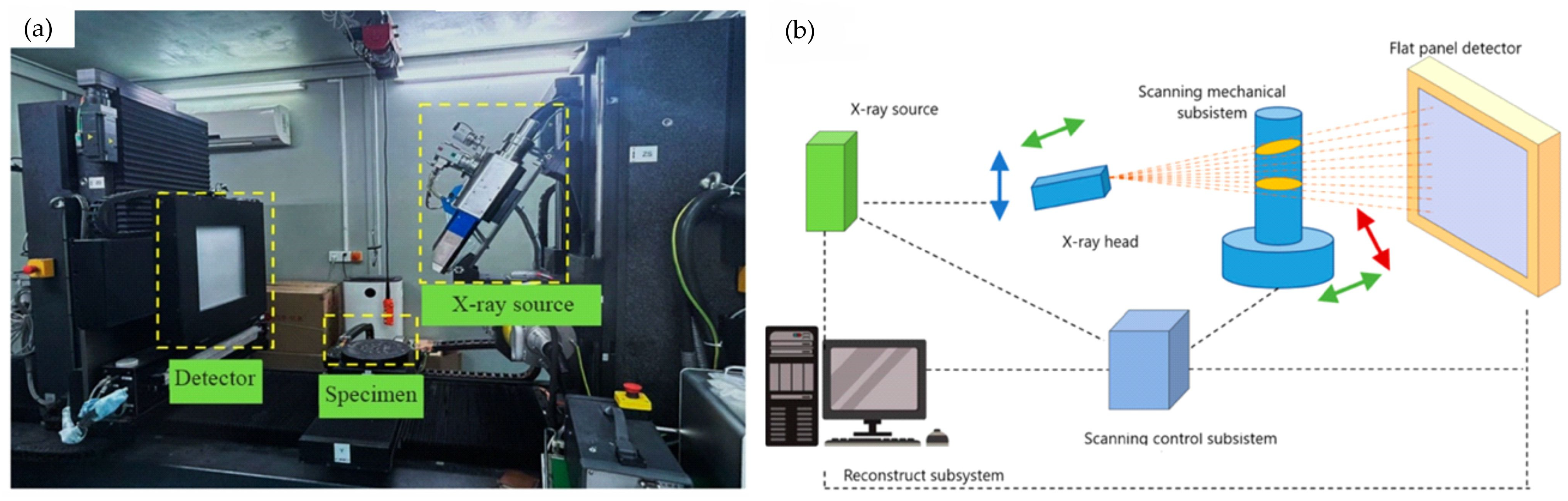
The internal structure of the samples was examined using a laboratory-grade computed tomography scanner, YXLON Cheetah EVO PLUS (Comet Yxlon; Hamburg, Germany) (see
Figure 1).
Scanning parameters were as follows:
Detector type: X-ray;
Voltage: 16,000 kV;
Current: 0.20 mA;
X-ray energy: 6 MeV;
Spatial resolution: 2.5 LP/mm;
Pixel matrix: 1024 × 1024;
Pixel size per slice: 109 μm.
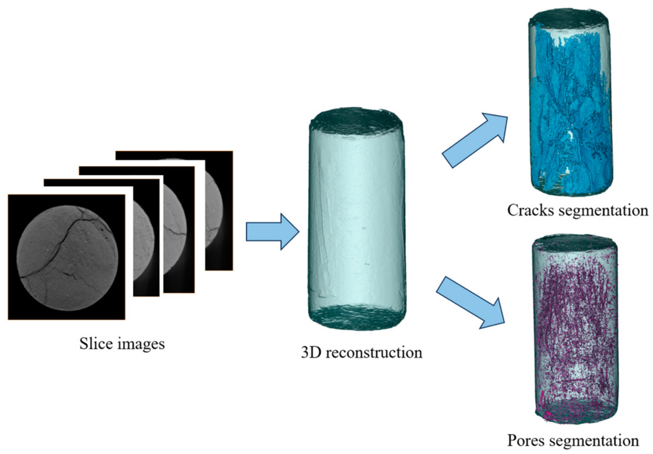
For processing the 2D slice images obtained through CT, the 2023 version of Avizo software was used to perform image analysis and 3D visualization. Threshold segmentation and three-dimensional reconstruction technologies were employed to process and visualize the internal structure of the studied samples (see
Figure 2).
2.5. Analysis of Bond Formation and Pore Development
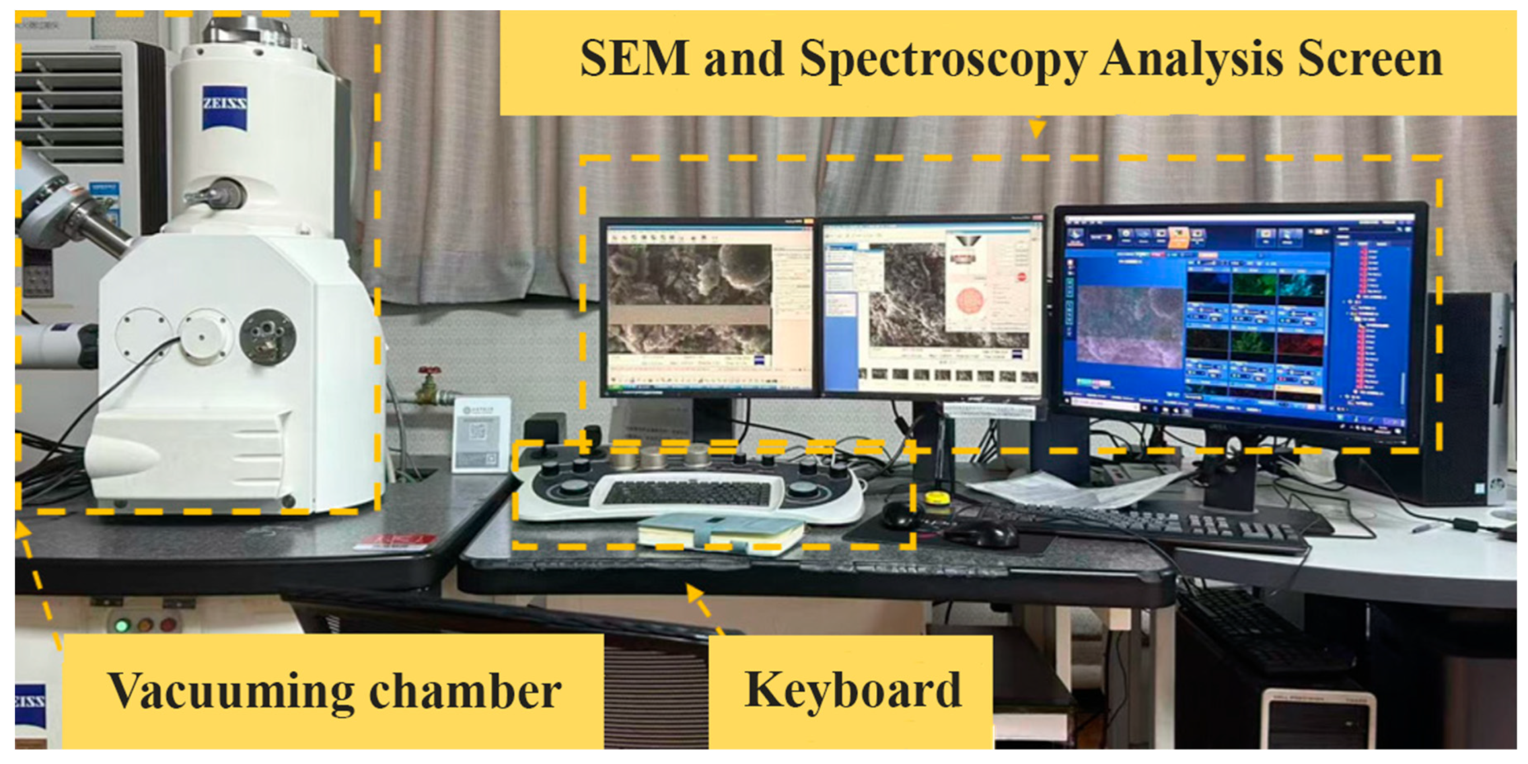
Scanning of the samples was carried out using a Zeiss Evo 18 Scanning Electron Microscope (SEM) (Carl Zeiss, Oberkochen, Germany) to observe the internal processes involved in the formation of the backfill composite matrix during curing. The following phenomena were studied: hydration processes, the formation of C-(A)-S-H gels and ettringite (AFt), crystalline lattice development, pore formation, and the nature of internal bonding within the matrix (see
Figure 3).
Key SEM operating conditions were as follows:
Resolution: 3 nm;
Accelerating voltage: 20 kV;
Magnification range: ×5 to ×1,000,000;
Beam energy: 20 keV.
The analysis was conducted on the fracture surfaces of specimens previously subjected to uniaxial compression testing. To enhance image quality, dust and fine particles were removed using an air stream, and to improve the electrical conductivity of the samples, a double coating of carbon was applied to their surface.
3. Results and Discussion
3.1. Pore and Crack Distribution in the Hardened Composite (2D Scanning Analysis)
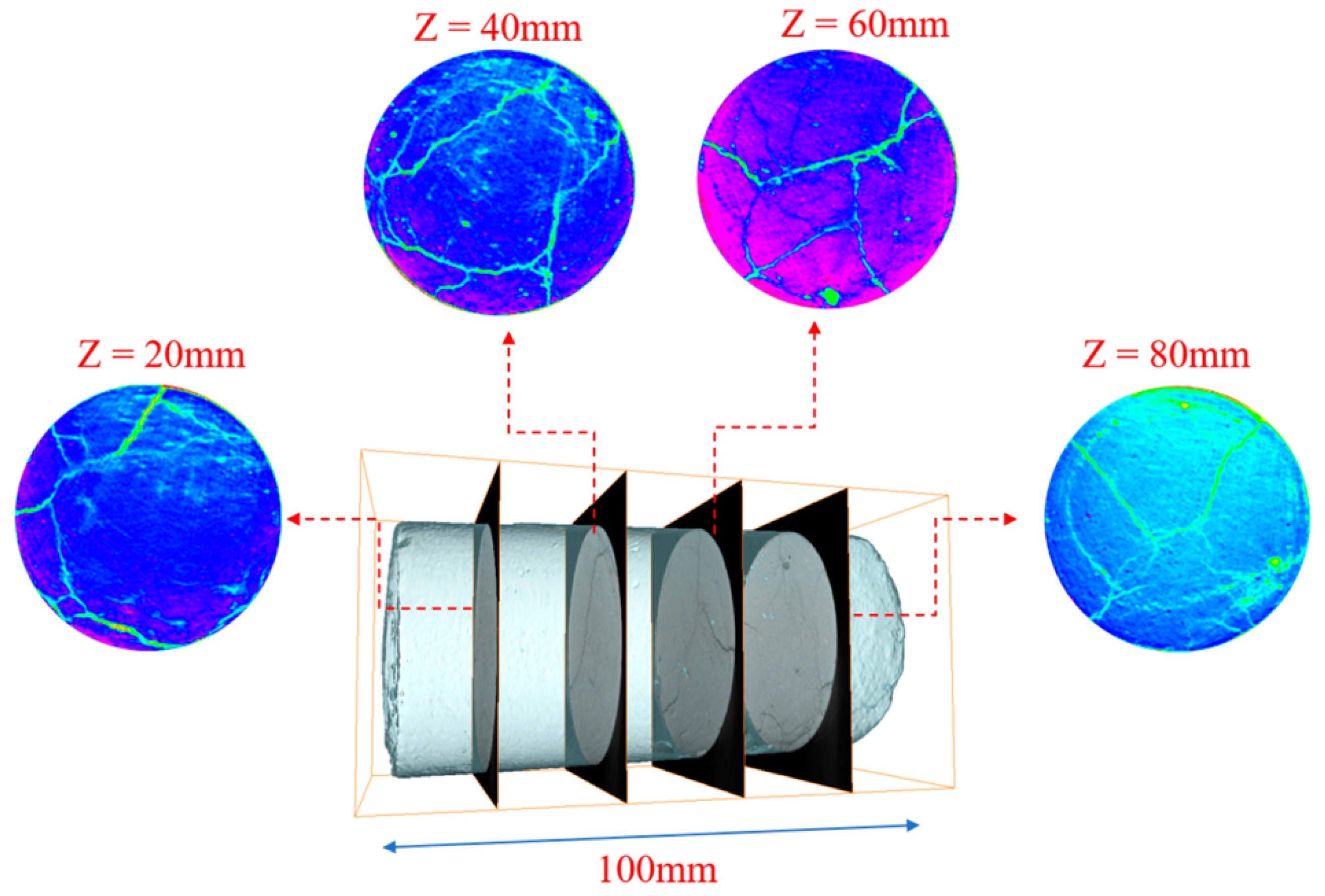
In this section of the study, parallel, equidistant planes were identified within the analyzed sample (see
Figure 4). The data for these planes were obtained through computed tomography (CT) scanning. The resulting 2D slices were post-processed using false-color imaging in the latest version of ImageJ software (version 1.53t).
Since a homogeneous mass was obtained during the preparation of the backfill mixture, individual fibers could not be distinguished after curing. As a result, fiber structures are not visible in the presented images.
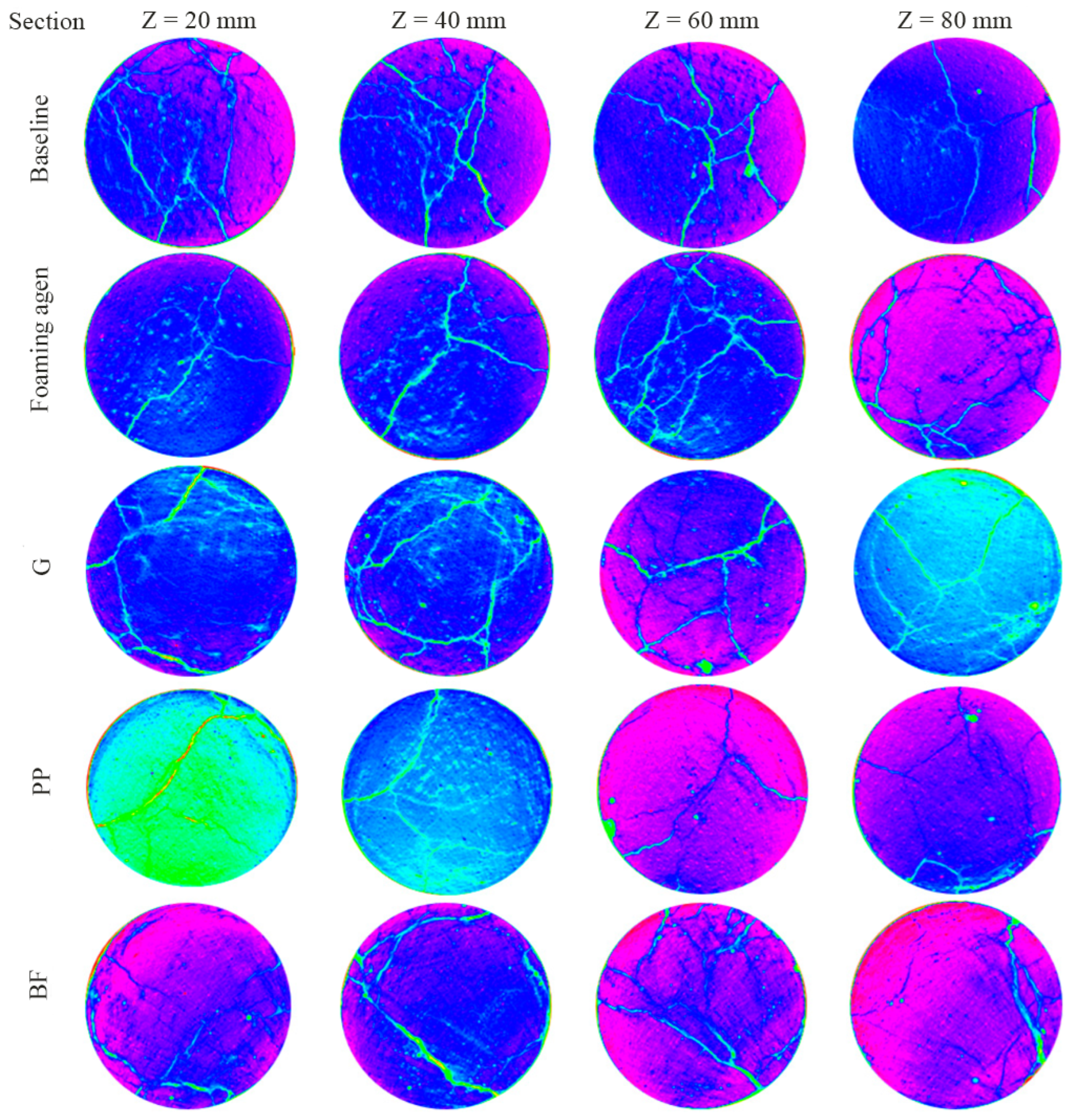
Figure 4 shows a two-dimensional layered model representing the crack formation and failure process within the sample. The blue and violet circles depict cross-sections of the backfill composite specimens, while the green lines of varying thickness represent small, medium, and major cracks formed at the moment of structural failure. The bright specks scattered along the outer edges of the slices correspond to pore structures.
Figure 5 presents the results of crack development obtained through two-dimensional scanning for backfill composite samples with different mix designs. Under loading conditions, micropores in the samples begin to evolve into cracks, as clearly visible in the 2D cross-sections. This observation confirms that as soon as the hardened sample is subjected to external stress, internal deformation and extrusion begin to occur, resulting in changes to the matrix structure.
In non-reinforced samples (i.e., those without fibers), crack propagation typically begins at the center of the specimen and spreads uniformly in all directions. The primary fracture that led to the failure of the tested sample propagated vertically. Due to the presence of above-average pore sizes, initial crack formation often occurs at the junctions of these larger pores and subsequently propagates through the interconnected micropores. The total crack volume (including both microcracks and critical fractures) was significantly higher in non-reinforced samples compared to those that incorporated reinforcing components (fibers) into the mix design.
In contrast, reinforced samples—regardless of fiber type—exhibited an opposite trend. Cracking in these specimens initiated at the edges, even though pores were also present in the central regions. As the applied load increased, the main crack formation process occurred at the periphery of the samples. Notably, these edge-initiated cracks did not propagate toward the center, where no visible or significant structural changes were observed.
These results clearly demonstrate the bridging effect of the reinforcing fibers, which impedes crack propagation, enhances the integrity of the hardened matrix, and not only absorbs part of the applied stress but also reduces stress concentration within the specimen.
3.2. Pore Structure
The strength and stability of the hardened backfill composite samples are significantly influenced by the presence of pores, their size distribution, and total volume. To analyze pore structure at the microscopic level and to assess the influence of reinforcing fibers on the cured composite, Avizo software (version 1.5) was used for 3D reconstruction and visualization.
One of the key parameters defining the structural framework of the hardened backfill composite is its porosity. Porosity is calculated using the following formula [
43]:
where
ε—porosity,
Vpore—total pore volume,
Vall—total volume of the backfill composite sample.
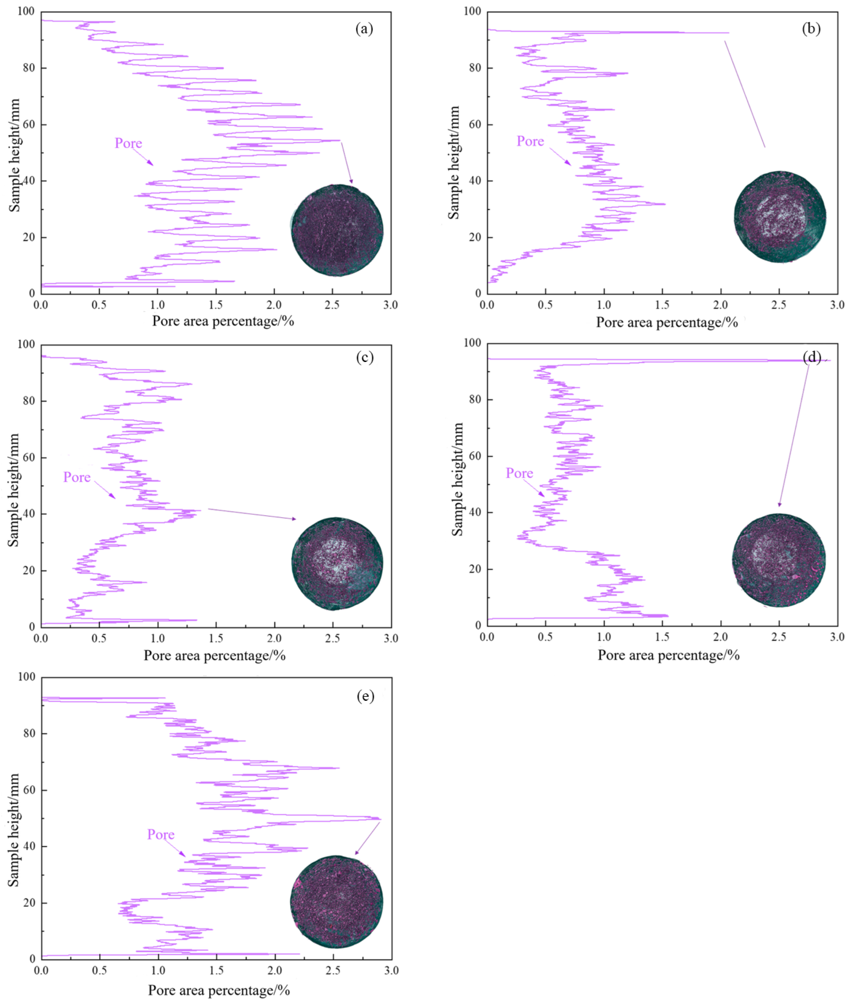
Figure 6 illustrates the relationship between the total pore area and its vertical distribution along the sample height.
A separate group of pores (region) is associated with the overall pore zone identified on each cross-sectional slice. The results demonstrate that in the reference sample (
Figure 6a), which was produced without the addition of a foaming agent or reinforcement, significant amplitude fluctuations are observed. In contrast, the sample with a foaming agent (
Figure 6b) exhibits smoother amplitude curves. Reinforced samples show gentler oscillations, indicating that the pore distribution becomes more uniform when a foaming agent is added.
In
Figure 6b,d, peak fluctuation values are observed at the top part of the samples. This indicates lower compaction density in the upper region, confirming that pores tend to accumulate toward the top during sample formation.
3.3. Three-Dimensional Reconstruction of Crack Distribution in Hardened Samples
During the uniaxial compression testing of the samples, internal structural changes occur that may not be visually apparent but significantly influence mechanical strength, failure resistance, and residual load-bearing capacity. In
Section 3.1 and
Section 3.2, the instability regime and the formation and propagation of such instability were analyzed through porosity and crack development mechanisms.
To further investigate the failure behavior of the hardened backfill composite, this study applied 3D reconstruction technology by importing laboratory-acquired 2D CT scan data into specialized digital processing software (Avizo 3D Pro Software, version 2024.2).
The resulting three-dimensional model provides a more accurate representation of crack initiation, growth, and propagation, offering a clearer scientific basis for failure analysis and improving the intuitive understanding of the process.
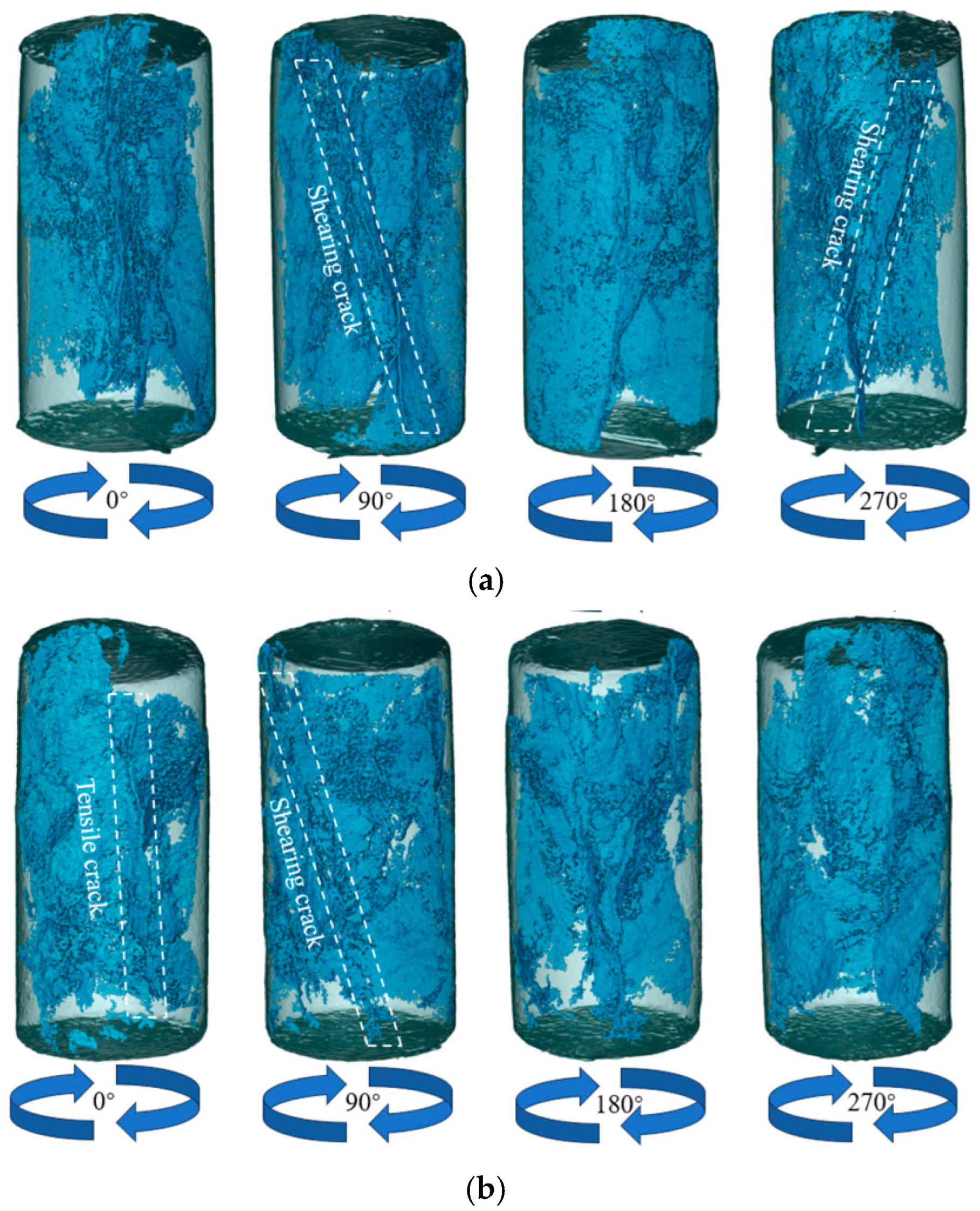
Figure 7 presents a 3D reconstruction image showing the spatial distribution of cracks within the structure of the hardened backfill composite. The internal fracture process (crack development) was captured from multiple viewing angles—0°, 90°, 180°, and 270°—allowing for the construction of a comprehensive 3D model and visualization of the spatial and geometric distribution of cracks
The failure of the sample represents a typical matrix failure mode, meaning a breakdown of the internal structural bonds. During uniaxial compression, the disruption of internal bonds occurs as a result of shear forces and/or increased internal tensile stresses that exceed the internal compressive strength. Based on this, structural cracks can generally be classified into two types: shear cracks and tensile cracks.
Figure 7a illustrates that the primary crack, which ultimately caused the failure of the tested sample, developed parallel to the applied axial load. The propagation of this dominant crack along the direction of maximum stress is characteristic of shear failure. Furthermore, the symmetrical appearance of parallel cracks on opposite hemispheres of the specimen indicates the formation of a single, dominant fracture plane, which effectively split the sample into two parts.
After the foaming agent was introduced into the backfill composite mix, the general failure pattern remained largely unchanged, with minor exceptions (
Figure 7b). In this image, both the dominant fracture and a secondary microcrack, developing nearly parallel to it, can be observed. This phenomenon is attributed to the increased pore formation within the hardened composite matrix caused by the foaming agent, which in turn indicates reduced structural stability under load.
The introduction of reinforcing fibers into the composite mix fundamentally altered the crack propagation behavior. In
Figure 7c,d, the samples exhibit a notably preserved structural integrity. In other words, reinforced samples are characterized by the absence of dominant cracks. The fibers bind the hardened matrix into a stronger and more stable structure. Failure in such specimens occurs gradually rather than suddenly, with the structure sequentially absorbing destructive stresses. Reinforcing fibers are able to maintain cohesion in fractured regions and continue to bear loads for some time even after localized failure has occurred.
3.4. Relationship Between Applied Load, Mechanical Damage, Crack Development, and Porosity
The analysis of pore distribution within the backfill composite matrix, along with the development and propagation of cracks and pore surface roughness, allows for the identification of the underlying failure mechanisms and the evolution of structural breakdown. It also reveals the correlation between porosity, total crack volume, and the strength of the tested samples.
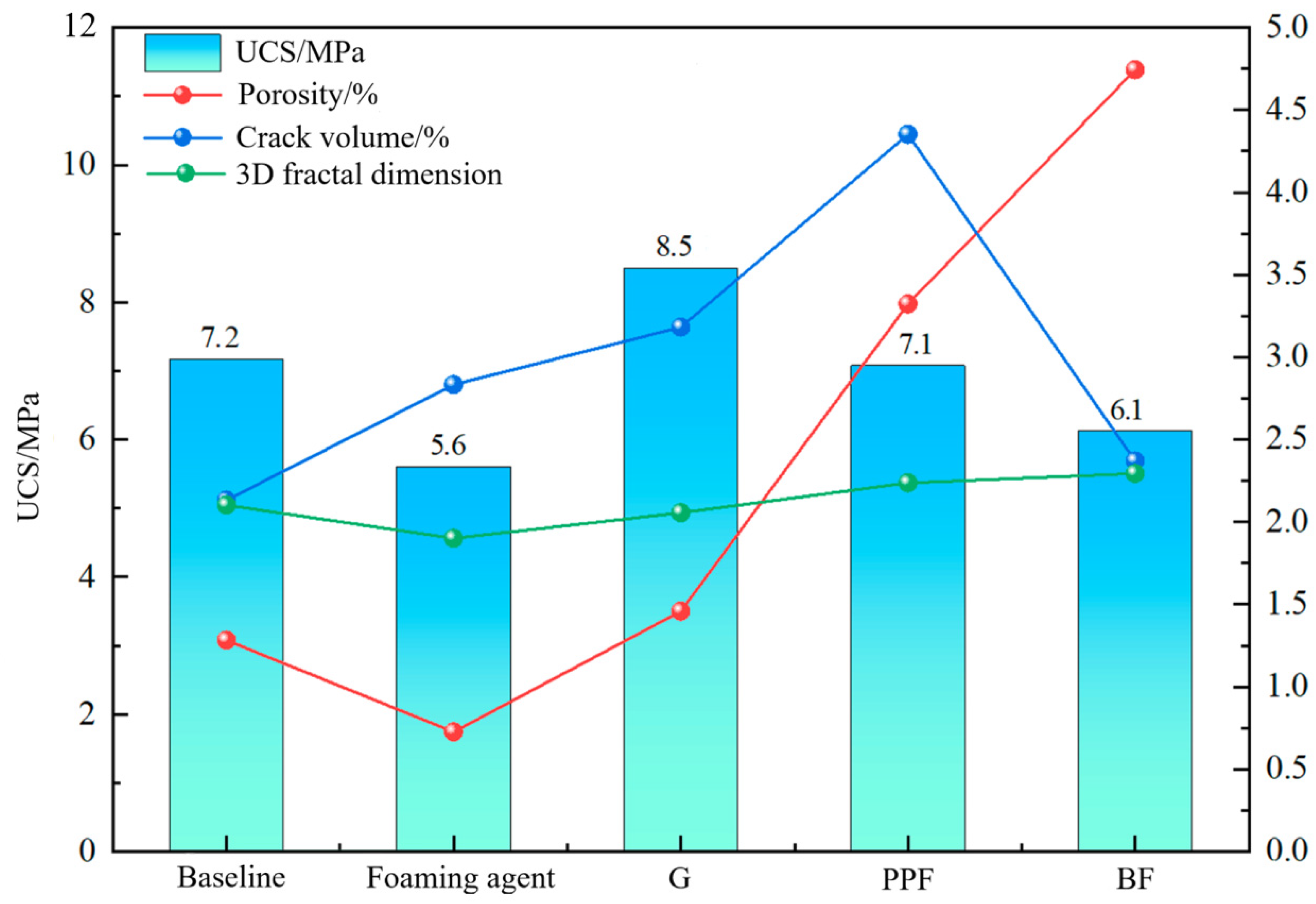
Figure 8 presents the relationship between porosity, the 3D fractal dimension, and the total volume of formed cracks, all of which take into account the composition of the backfill mixture.
Analysis of the obtained dependencies revealed that the best performance was demonstrated by the samples containing glass fibers in their composition. In these samples, porosity values were comparable to those of the reference samples, and even higher than in samples containing the foaming agent. The relatively high compressive strength despite similar or higher porosity can be explained by the ability of the fibers to bridge different areas of the matrix. In the event of initial failure, the fibers take on part of the load and help maintain structural integrity for a longer period.
When polypropylene or basalt fibers were added to the backfill composite formulation, the porosity of the matrix increased sharply during curing, which resulted in a reduction in load-bearing capacity. This effect is attributed to the fact that different types of reinforcing fibers influence porosity differently. The addition of glass fibers caused minimal change in porosity, while polypropylene and especially basalt fibers led to a noticeable increase in porosity.
This phenomenon is likely due to differences in the microstructure of the fiber surfaces. Glass fibers have a smooth surface, which minimizes air entrapment during mixing. In contrast, polypropylene and basalt fibers possess pronounced surface roughness and microfibrils, which, under intense mixing, trap and retain air bubbles within the cement matrix.
This effect is most pronounced in basalt fibers, which tend to aggregate and exhibit a well-developed spatial structure. As a result, increased air entrapment raises the total porosity of the material by forming entrained pore zones, which in turn reduces the mechanical strength of the hardened composite—particularly its uniaxial compressive strength.
Despite the increase in porosity caused by the addition of structurally textured fibers (polypropylene and basalt), the overall strength of the hardened samples remained at a satisfactory level. This is due to the internal reinforcement function of the fibers: they are evenly distributed throughout the matrix and intercept stress concentrations arising during deformation.
Thanks to their spatial configuration and strong adhesion to the matrix, fibers prevent the spread of microcracks and localize damage zones. This effect is especially significant in basalt fibers, which have a dense system of microfibrils providing additional mechanical interlocking. Under conditions of increased porosity, fibers play a key role in maintaining structural integrity, slowing crack propagation, and redistributing localized stress.
Thus, a compensatory effect can be observed: while increased porosity theoretically reduces composite strength, the presence of spatially oriented fibers partially or completely offsets this effect due to their reinforcing and stabilizing function within the matrix.
Relatively contradictory results were obtained when using basalt fibers. Despite the fact that these samples showed the highest total porosity, they maintained an average compressive strength comparable to samples with significantly lower porosity. At first glance, this may contradict classical assumptions about the relationship between strength and porosity.
However, analysis of crack volume revealed that these samples had the lowest degree of cracking after failure. This confirms that basalt fibers, due to their spatial architecture and high adhesion to the composite matrix, are highly effective at limiting crack development and propagation.
Therefore, even if compressive strength decreases due to increased porosity, the structural integrity of the backfill composite is preserved to a high degree. The fibers act as crack stoppers, forming a secondary load-bearing network that prevents rapid disintegration of the specimen. This explains the material’s continued resistance to external loads and highlights the critical role of fibers in forming a crack-resistant composite structure.
An analysis of the 3D fractal dimension of the pore space revealed that this parameter for all studied backfill formulations fell within a relatively narrow range, from 2.00 to 2.31, indicating a comparable overall level of porosity, but different pore morphologies and structural organizations of the materials.
In the reference composite (binder + inert filler), the fractal dimension was approximately 2.20, which corresponds to a uniform pore distribution in 3D space and a lack of pronounced structural hierarchy. When a foaming agent was added, the fractal dimension decreased to ~2.00, reflecting a disruption in spatial regularity and a more random pore distribution due to active foaming and the potential coalescence of bubbles.
In samples containing both foaming agent and glass fiber, the fractal dimension returned to approximately 2.20, demonstrating the stabilizing influence of smooth fibers on the spatial organization of the structure. The addition of polypropylene fibers increased the fractal dimension to around 2.25, indicating a more complex and branched pore network, likely resulting from increased heterogeneity.
The highest fractal dimension values (~2.30 and above) were observed in samples containing basalt fibers, which are characterized by a well-developed system of microfibrils. This suggests the formation of a pore skeleton with a high degree of embeddedness and fractal complexity, in which fibers act as structural elements, facilitating air entrapment and forming a hierarchically organized micropore network.
It should be emphasized that the correlations presented in
Figure 8 represent a mechanistic linkage between microstructural parameters obtained from CT scanning and the macroscopic mechanical performance of the backfill composites. The uniaxial compressive strength is shown to depend not solely on total porosity, but on the combined effects of pore morphology, crack volume, and structural connectivity, as reflected by the 3D fractal dimension. In fiber-reinforced systems, this relationship is further modified by crack-bridging and stress redistribution mechanisms, which decouple strength from porosity alone. Therefore, the CT- and fractal-based analyses provide a physically grounded interpretation of strength evolution rather than a purely empirical statistical correlation.
Although direct pull-out or interfacial bonding tests were not performed in this study, the observed reduction in crack volume, increased matrix continuity, and significant strength enhancement in fiber-reinforced samples serve as indirect indicators of effective crack-bridging and arrest mechanisms. This interpretation is consistent with previous research on fiber-reinforced backfills, where similar microstructural evidence has been accepted as validation of fiber–matrix interaction effects in brittle cementitious systems [
24,
31,
35,
37].
3.5. Formation Mechanism of the Backfill Composite Matrix
The matrix activation was based on a lime–sulfate activation approach, using Ca(OH)2 at 4% by slag mass and CaSO4·2H2O (FGD gypsum) at 6% by slag mass, with a water-to-binder ratio (w/b) of 0.35. The externally added Ca(OH)2 provides an alkaline environment and acts as a source of Ca2+, which accelerates the dissolution of the slag’s glassy phase and promotes the formation of C-(A)-S-H gels. The calcium sulfate initiates the formation of ettringite (AFt), which later partially transforms into monosulfate (AFm). Mg-containing components in the slag contribute to the formation of layered double hydroxide (LDH) phases, which stabilize the pH level and the pore structure of the matrix.
To achieve controlled volume expansion, a surfactant-based foaming agent derived from sulfite-alcohol stillage was introduced at 0.1–0.5% (dry solids basis). This ensures uniform air entrainment without degrading the structural integrity of the load-bearing matrix.
The key stages of the hydration process can be described by the following reactions:
Dissolution of the slag glass phase:
Formation of ettringite and AFm:
The externally added Ca(OH)2 rapidly raises the pH and provides free Ca2+ ions to promote early C-(A)-S-H gel formation. The gypsum initiates the formation of early ettringite (AFt). The hydration system resembles Portland–slag cement hydration, though without clinker formation.
The high alkalinity of the pore solution, derived from Ca(OH)2, accelerates the dissolution of the slag’s amorphous phase, which is rich in Si and Al. The availability of Ca2+ further promotes the growth of low-basicity C-(A)-S-H gels, with a Ca/Si ratio of approximately 1.2–1.5.
The introduction of sulfate ions from gypsum redirects part of the dissolved aluminum into the formation of AFt (ettringite), providing an early rigid framework. As the SO42− ions are consumed, a portion of AFt gradually transforms into AFm (monosulfate).
Simultaneously, magnesium present in the slag leads to the development of LDH phases (hydrotalcite-like structures), which help stabilize both the pH and the pore architecture of the composite.
3.6. SEM Investigation
To verify the proposed matrix formation mechanism and validate the hydration pathway described above, a detailed microstructural analysis was conducted using scanning electron microscopy (SEM). This approach enables direct observation of the phase assemblage and morphological features formed during the early stages of hydration.
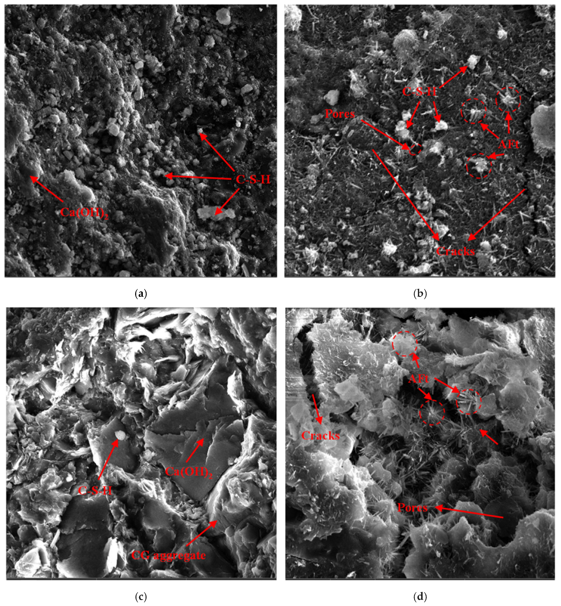
Figure 9 presents the microstructure of the hardened backfill composite at an early curing stage. As shown, the reference (baseline) sample (
Figure 9a) exhibits a substantial quantity of flocculent hydration products, primarily C–S–H gels, along with a significant concentration of portlandite (Ca(OH)
2). The formation of C–S–H gels contributes to a denser microstructure, thereby enhancing the overall strength of the composite.
In contrast,
Figure 9b illustrates the effect of polypropylene fiber on the hardened matrix. Due to the combined influence of the foaming process and fiber addition, the microstructure shows an increase in pore volume and microcrack development. Compared to
Figure 9a, the fiber-reinforced sample exhibits a reduced amount of C–S–H gel but a greater presence of interwoven, needle-like AFt crystals (ettringite). These elongated structures form a denser skeletal framework, which also contributes positively to the mechanical strength of the composite.
Figure 9c illustrates the combined effect of the foaming agent and glass fiber on the microstructure of the hardened backfill composite. The sample exhibits a significantly increased presence of portlandite (Ca(OH)
2), which appears in the form of thick, rounded flake-like crystals. These morphological changes suggest that the formation of such robust flake-shaped portlandite is facilitated by the presence of C–S–H gels, which densely fill the matrix pores. The resulting microstructure is denser and contributes to improved mechanical integrity of the composite.
In
Figure 9d, the use of basalt fiber in combination with the foaming agent results in a comparatively looser and more porous microstructure. Notably, visible microcracks are already present at this early stage, and the matrix is predominantly composed of needle-like AFt (ettringite) crystals. This morphology correlates with the lower uniaxial compressive strength observed in samples reinforced with basalt fiber, as confirmed by mechanical testing. The increased porosity and pre-existing cracks likely diminish the load-bearing capacity of the hardened composite in this configuration.
The comparative analysis of the SEM images (
Figure 9) provides insight into the microstructural factors that influence the mechanical performance of each fiber-reinforced variant.
The reduced compressive strength observed in sample 9b (polypropylene fiber) and sample 9d (basalt fiber), relative to the reference sample (9a), can be attributed primarily to increased porosity and microcrack formation. Both polypropylene and basalt fibers possess a surface morphology that tends to entrap air during mixing, particularly when used in combination with a foaming agent. This dual mechanism—fiber-induced air entrapment and deliberate pore generation through foaming—leads to an expanded void structure. In the case of basalt fiber, which often presents a split or frayed surface texture, the amount of retained air is even greater, contributing to the visibly looser and cracked matrix seen in
Figure 9d. These conditions not only create more nucleation sites for pore growth but also allow excessive development of elongated AFt crystals, which thrive in open, moisture-rich environments. The proliferation of needle-like ettringite may superficially reinforce the matrix, but the associated porosity ultimately undermines structural integrity under compressive loads.
In contrast, sample 9c (glass fiber) demonstrates superior microstructural compactness and higher strength. This can be attributed to the smoother, non-absorbent nature of glass fiber, which reduces unintentional air entrapment during mixing. As a result, fewer voids are introduced beyond those generated by the foaming agent. Furthermore, glass fibers appear to promote the formation of dense flake-like portlandite crystals, which are morphologically distinct from the needle-like AFt structures observed in other samples. These robust, rounded particles are thought to grow preferentially in constrained pore spaces where the formation of elongated crystals is limited. In such confined environments, C–S–H gels and plate-like Ca(OH)2 intergrow, filling voids more effectively and reinforcing the matrix with a cotton-like interlocked morphology. This denser packing enhances both the mechanical strength and long-term stability of the hardened composite. Additionally, the fibers may provide a bridging effect across microcracks, further contributing to crack resistance and matrix cohesion.
Overall, these findings underscore the critical role of fiber morphology and its interaction with foaming behavior in determining the resulting microstructure and, consequently, the mechanical performance of backfill composites.
3.7. Limitations and Directions for Future Research
Although this study does not include a formal Life Cycle Assessment (LCA) or quantitative economic modeling, the environmental and cost-efficiency advantages of the developed backfill composite are rooted in its material composition and deployment strategy. All major constituents—including the binder system, inert filler, and chemical activators—are sourced exclusively from industrial waste streams, entirely replacing specially mined raw materials. This approach not only avoids the environmental footprint associated with extraction and transportation, but also transforms waste into a value-added resource, eliminating surface storage needs. Additionally, the use of foaming technology ensures full volumetric filling of mined-out voids, effectively reducing the risk of underfilling and enhancing geotechnical safety by stabilizing the excavation geometry. These combined factors align with sustainable mining practices and underscore the ecological rationale outlined.
This study primarily focuses on the mechanical integrity and volumetric stability of the backfill composite. Industrial waste materials may contain potentially mobile trace elements. The utilization of these materials in a chemically bonded, monolithic form offers an ecological benefit by eliminating surface disposal; however, the possibility of long-term leaching under underground conditions cannot be fully excluded. Future research should investigate the immobilization efficiency of the matrix and assess the potential for heavy metal migration from the hardened composite under various hydrogeochemical conditions.
The present study focused on the initial design and feasibility of a monolithic, expanding backfill composite composed of industrial by-products. While the current results demonstrate promising strength and structural integrity, future investigations should include systematic assessments of strength development over time, temperature-dependent curing behavior, and chemical stability under underground conditions—particularly in the presence of mine water. These factors are crucial for full-scale deployment and will be addressed in our subsequent research.
While the theoretical hydration pathway predicts the formation of low-basicity C-(A)-S-H gels and the gradual transformation of AFt into AFm phases, these products were not distinctly identified in the SEM images collected during this study. This absence can be attributed primarily to the early curing stage at which the microstructural analysis was conducted. The formation of well-developed C-(A)-S-H gels typically requires a longer hydration period to allow for sufficient polymerization and densification of the calcium silicate hydrate network. At the initial stages, these gels often exist in a poorly crystalline or amorphous form that lacks clear morphological features distinguishable under conventional SEM magnifications, particularly in the absence of high-resolution imaging or complementary techniques such as TEM or XRD.
Similarly, the transformation of needle-like AFt (ettringite) into plate-like AFm (monosulfate) is a time-dependent process, governed by sulfate ion depletion and internal redistribution of aluminum. This conversion generally occurs at later stages of hydration, especially under sealed or saturated curing conditions. Since the microstructural examination in this study was limited to early-age samples, the AFt → AFm transition likely had not progressed sufficiently to yield detectable AFm phases. Further research is planned to investigate the long-term phase evolution, including delayed C-(A)-S-H development and AFt transformation pathways, using extended curing times and advanced characterization methods.