Article

Technogenic Waste in Backfill Composite Is a Paradigm of Circular Economy

by
Marat M. Khayrutdinov
1,*,
Alexander V. Aleksakhin
2,
Tatiana N. Kibuk
2,
Lyudmila N. Korshunova
2,
Maria A. Lozinskaya
2,
Olga Yu. Legoshina
3,
Oleg O. Skryabin
4 and
Galina V. Kruzhkova
5
1
Itasca Consultants GmbH, Leithestrasse Str., 111a, 45886 Gelsenkirchen, Germany
2
Economics Department, National University of Science and Technology “MISIS”, Leninsky Avenue, 4, 119991 Moscow, Russia
3
Department of Business Informatics and Production Management Systems, National University of Science and Technology “MISIS”, Leninsky Avenue, 4, 119991 Moscow, Russia
4
Department of Industrial Management, National University of Science and Technology “MISIS”, Leninsky Avenue, 4, 119991 Moscow, Russia
5
Department of Engineering Cybernetics, National University of Science and Technology “MISIS”, Leninsky Avenue, 4, 119991 Moscow, Russia
*
Author to whom correspondence should be addressed.
Mining 2025, 5(3), 57; https://doi.org/10.3390/mining5030057
Submission received: 30 June 2025 / Revised: 8 August 2025 / Accepted: 5 September 2025 / Published: 15 September 2025

Abstract

The depletion of shallow coal reserves necessitates a shift from open-pit to underground mining, increasing the need for safe and efficient backfill systems. However, traditional backfill materials—especially cement—are costly and environmentally burdensome. To address this, our study explores a sustainable alternative using industrial waste, contributing to the principles of a circular economy. This research presents a novel backfill formulation that achieves full cement replacement through the use of fly ash, supplemented with nanocrystalline silica and glass fiber to enhance strength and setting dynamics. Eighteen sample sets were prepared for each composition, using consistent mixing, curing, and testing protocols. Mechanical strength was evaluated at multiple curing intervals alongside microstructural characterization using SEM and XRD. The results show that mixtures containing nanomodified silica and fiber exhibit significantly improved compressive, shear, and splitting strength—up to 40% higher than fly ash-only compositions. Microstructural analysis revealed accelerated C-S-H gel development, reduced porosity, and more uniform pore structures over time. These findings confirm the mechanical viability and economic potential of waste-based backfill systems. The proposed formulation enables safer underground operations, improved extraction efficiency, and reduced environmental impact—offering a scalable solution for modern coal mining.

1. Introduction

Depletion of shallow coal reserves dictates a transition from open-pit mining to underground operations [1] and/or and low-quality coal mining. Currently, about 20% of coal in Russia is extracted using underground methods [2]. In the context of China, the world’s leading coal producer, extracts 95% of its coal through underground mining [3].
High resource losses during coal deposit extraction (up to 50%), which occur due to the pillars left behind [4], and the occurrence of several man-made disasters (roof collapses, pillar failures, methane penetration through fracture systems and its accumulation in created voids, etc.) [5,6,7] have led to the adoption of systems with cemented backfill in Chinese coal mines [3].
Due to the high cost of backfill materials and backfilling operations, this technology has historically been used only in the development of valuable and highly valuable ore deposits [8,9,10]. For example, in the early 20th century, in 1921, at the Witwatersrand gold mine in South Africa, pillars were replaced with concrete disks to recover remaining ore, and later with poured concrete columns [11]. A similar technique was applied slightly later in 1922 at the Champion Reefs mine in the Kolar Gold Fields gold deposit in India [12]. However, this technology did not gain widespread use due to the labor-intensive process and its low productivity [11,13].
Later, in 1930, a two-stage extraction method was successfully tested at the Sullivan Mine in Canada. Pipelined transport was used to deliver the backfill mixture into the stopes, which increased the efficiency of backfilling operations. The mined-out stopes were filled with a cementitious material, with specially mined sand used as an inert aggregate. Once the artificial mass in the first-phase stopes achieved the necessary strength characteristics, the extraction of the remaining inter-stope pillars (second-phase stopes) began. However, the large volumes of backfill required caused a sharp increase in the cost of cement and construction sand, leading to higher backfill costs and, consequently, reduced economic viability of the extraction process [14].
A more successful example of applying a two-stage extraction method with cemented backfill is the technology implemented by Noranda Mines (Rouyn-Noranda, Quebec, Canada) in 1933–1935 during the development of the Horne copper-pyrite deposit [15,16]. The core of this technological scheme was the revolutionary use of a multi-component backfill composite, incorporating industrial waste into the backfill mixture, such as beneficiation tailings (as a replacement for inert aggregates) and granulated blast furnace slag (as a partial substitute for cement binders) [17]. The adoption of this technology nearly doubled the recovery factor, thereby increasing the economic efficiency of the deposit’s development. By 1940, this led to widespread implementation of multi-stage extraction systems with cemented backfill in other Canadian deposits: Sullivan Mine, Quemont, Falconbridge, Madsen, and Red Lake. By 1949, this technology spread to Finland Outokumpu mine (Outokumpu, Nort Karelia, Finland) and by 1951 to Poland (the Juliana Marchlewski mine, formerly Deutsch-Bleischarleygrube, the Ludwik Waryński mine, and Orzeł Biały mine) [18,19].
In the USSR, the use of cemented backfill in underground mining began in the early 1950s, with trials conducted at the Tekeli, Leninogorsk, and Zyryanovsk mines [20]. From the late 1950s, in the USSR, cemented backfill technology became the priority in the design and construction of new mines developing above-average-value ores. For example, during the planning of the Gai copper-zinc pyrite deposit (operations began in 1959) and the Oktyabrskoye copper-nickel ore deposit (operations began in 1969), project documentation included detailed formulations of backfill mixtures, technological schemes for composite preparation, and systems for delivering the mixture to the placement site [21].
Backfilling operations at coal mines were tested earlier than at mines extracting valuable ores. For instance, hydraulic backfill was used at the Chwałowice Coal Mine in the Silesian Coal Basin (Rybnik, Selesian Voivodeship, Poland) in 1878 and at the Lehigh Coal Mine Company in Summit Hill, PA, USA in 1880, which extracted anthracite. However, this technology did not advance further in coal mining due to its low effectiveness [22]. The hydraulic backfill used at these mines lacked binders, resulting in insufficient strength and high shrinkage, making it impossible to extract the remaining pillars [23]. Additionally, the use of hydraulic backfill increased water inflow in the workings, leading to additional dewatering costs [24]. Cemented backfill was initially considered unpromising for coal deposits due to the high cost of backfill operations and the relatively low value of coal [25].
Requests for the development of cemented backfill formulations and technologies for coal mining began to emerge due to deeper mining, the development of sites with complex geological conditions, mining under protected structures, and the extraction of spontaneously combustible coal seams, among other factors [26,27].
In the USSR, in 1947 at the Kemerovo Mine No. 3 in Kiselevsk, the successful implementation of coal seam extraction under an artificial arched concrete roof and artificial concrete barrier pillars was achieved [28]. Later, in 1952, a technology with cemented backfill was developed and successfully tested for thick seams of spontaneously combustible coal at the Prokopyevsk-Kiselevsk coal deposit [29]. However, the high cost of backfill operations and materials, as well as the post-war cement shortage, halted these studies at the pilot-industrial stage, preventing the widespread adoption of cemented backfill in coal mining [26,30].
However, the use of industrial waste from the mining operation itself, as well as from other enterprises in the region, in the composition of backfill materials significantly reduced the cost of backfill operations [31]. This enabled the application of cemented backfill technology for coal extraction, even for deposits classified as having below-average economic value [32,33,34].
The artificially created mass based on industrial waste from coal mining operations allows:
  • Replacement of natural pillars, thereby increasing recovery rates;
  • More effective control of the stress–strain state of the rock mass;
  • Prevention of roof collapses;
  • Minimization of methane-conducting fracture formation;
  • Reduction in the risk of subvertical faulting in the overlying strata, thus preventing surface subsidence;
  • Elimination of voids, thereby reducing the likelihood of explosive accumulations of methane and coal dust.
Thus, the use of backfill in coal mining reduces the risk of coal, coal dust, or methane igniting in the workings, which enhances both the safety of operations and the working conditions of miners [5,35,36]. The backfill technology not only effectively controls the pressure of the overburden on the roof of the workings and the stope in the active mining area but also plays a critical role in the development of hazardous sections of the coal deposit and operations in high-stress zones [7,8,37,38,39].
The incorporation of industrial waste from the coal industry into backfill compositions aids in waste disposal within the mined-out space, reduces environmental impact, and minimizes degradation, thereby preserving a favorable living environment [31,32,33,34,35,36,37,38,39,40].
Developing cemented backfill composites requires constant adjustments to the formulation to produce a high-quality and durable artificial mass capable of bearing the load of the overlying strata for effective ground pressure management while maximizing the economic efficiency of coal extraction [20,33,41]. In cases where backfill technology is employed, backfill operations account for approximately 20% of the total production cost, with up to 75% of this being the cost of the cement binder [34,36,42]. Therefore, finding an alternative to cement binders would significantly reduce the cost of backfill materials and operations, thereby increasing the overall economic viability of coal deposit development [43].
The primary indicators characterizing the stability of the created artificial mass are its mechanical properties. However, the mechanical properties of an artificial mass based on industrial waste from coal mining are insufficient to fully withstand the rapidly changing stress–strain state of the rock mass and to resist the complex conditions arising during mining operations [20,33,36].
To improve the characteristics of the created artificial mass or backfill composite mixture, a wide range of additives and modifiers has been used [20]. Introducing such additives into the backfill composite formulation enhances its technological and performance characteristics [20,36,42,44]. Many of these additives are of industrial origin and are classified as waste materials, such as fly ash, granulated blast furnace slag, lignosulfonates, and others. Their use effectively reduces the cost of backfilling operations [20,43,44,45,46].
Research [43,44,45,46] has shown that the properties of an artificial mass created from a hardened backfill composite can be improved through both mechanical modifications (such as processing in various installations like mills, disintegrators, vibratory units, etc.) and chemical modifications, including the introduction of additives like nanomodifiers. Initially, additives introduced into backfill composite formulations were not categorized based on their interaction or effect on the components [20,44]. Later, a classification criterion (mode of action) was proposed, identifying three types: catalysts, plasticizers, and inhibitors [20]. To improve the mechanical and performance characteristics of the hardened backfill composite, some studies have employed inhibitors reinforcing fibers. All of this contributes to enhancing the microstructural properties of the material [20,47] and, consequently, its performance characteristics [42,43,44,45].
In the last decade, there has been an increase in the anthropogenic impact on the environment, the greatest impact of which is exerted by the mining and processing industry [48,49,50]. Large volumes of waste from the mining and processing industry in the form of waste rock from stripping and/or tunneling operations, enrichment tailings, metallurgical slag, etc., are stored in technogenic (man-made) storage facilities [51]. The lower the content of the useful component in the mined ore, the higher the volume of generated technogenic (man-made) waste [24,52,53]. Consequently, the content of the useful component in the mined raw materials directly characterizes the degree of man-made impact of the mining and processing industry on the environment [17,54,55]. As a result, an exponential increase in the accumulation of man-made waste is expected [56]. This trend has determined the need to find solutions to reduce the negative impact of the mining and processing industry and at the same time search for ways to improve the safety of mining operations [57,58]. The value of man-made waste as a potential product used to implement safe, environmentally balanced and cost-effective mining technology has been neglected for a long time [21,24]. One of the ways to use man-made waste in the mining industry is to replace specially mined, expensive components in the formulation of backfill composite [9,14,23,59]. The idea of realizing the potential of man-made waste is an integral part of creating a closed-loop (circular) economy [58].
Given the depletion of shallow coal reserves and the shift to underground mining, along with the deteriorating environmental conditions in mining regions and the experience gained from using cemented backfill technology in the extraction of valuable ore deposits, a transition from traditional coal mining technologies to those involving cemented backfill is necessary [60].
Thus, the main objective of this study is to select a backfill composite formulation with technological and performance characteristics that can improve the qualitative and quantitative extraction indicators while enhancing mining safety and maintaining (or possibly improving) the economic performance of the coal mining enterprise within the framework of a circular economy.
To achieve this goal, the following tasks must be addressed: replacing traditional (specially mined) components in the backfill composite formulation with industrial waste accumulated in the mining region; exploring the potential for improving the mechanical properties of the backfill composite through the introduction of modifying additives; and investigating the mechanical and operational properties of the mass created based on the proposed backfill composites.

2. Materials and Methods

2.1. Methodology

To conduct a comparative analysis of the strength characteristics of backfill composites with different formulations, mixtures were prepared using the same technology, with identical curing conditions and duration, and the same testing regime.
Sample preparation was carried out according to the standard methodology established by GOST 5802-86 [61] and GOST 10180-2012 [62], as described in [20], which will not be repeated here. The mixing process followed the principle of “from smaller to larger” to ensure better blending of all backfill composite components.
Mixing was performed using a laboratory planetary mixer MIKS-D-C (Geotester LLC, Neftekamsk, Russia). Optimal and efficient mixing was achieved due to the characteristic planetary motion of the mixer, which combines circular movement with rotation around its own axis. The planetary rotation speed was 62 rpm, increasing to 125 rpm, with an initial circular rotation speed of 140 rpm, increasing to 250 rpm. Glass fibers were mixed dry into the composite to ensure random spatial orientation, which is optimal for multidirectional stress environments typical in underground mining conditions.
To simulate conditions close to those found in underground mines, storage and curing of samples were conducted in specialized drying chambers that maintained constant temperature and humidity (T = 20 ± 2 °C; W = 95 ± 5%).
To study the dynamics of strength development, uniaxial compression, tensile, and shear tests were conducted on the 7th, 28th, 60th, and 120th days of curing.
Previous studies have shown that replacing 1% of the cement binder in a backfill composite based on waste coal rock with 10% fly ash preserves the rheological characteristics of the mixture and the mechanical properties after curing [63,64]. When using specially quarried sand as an inert filler, the cement binder content in the backfill composite can be reduced by 20–25% without compromising the rheological and mechanical properties of the composite [43,45,46]. Research on the effects of reinforcing inhibitors on the artificial mass demonstrated the positive impact of various types of fibers [20,43], nanocomposite fibers, and nanotubes [43]. The results showed a multifaceted influence of fiber on mechanical properties and transportability. An increase in fiber content in the backfill composite formulation from 0.1% to 1.0% led to an increase in both the rate of strength gain and peak strength values. However, increasing fiber content in the formulation sharply reduced the mixture’s transportability. The optimal fiber content in the backfill composite formulation was found to be 0.25–0.4% (regardless of fiber type) of the binder. Additionally [20], research established that increasing fiber content above 1% results in a sharp decline in strength characteristics due to poor component mixing, formation of fiber clusters, and the presence of air pockets, leading to increased porosity after curing [20,43].
Studies have also confirmed the positive impact of nanomodified additives on the technological and performance characteristics of the backfill composite. The optimal concentration of the nanomodified inhibitor in the formulation was experimentally determined Based on previous work, a program was developed for selecting the backfill composite formulation (Table 1).
Cement-based backfill composites are the most extensively studied; therefore, to explore the possibility of replacing cement with industrial waste (specifically fly ash in this study), formulation no. 1 was prepared as the benchmark.
Tests for uniaxial compression, shear, and splitting were conducted on samples with dimensions of 70 × 70 × 70 mm. The testing methodology for uniaxial compression used in this laboratory-scale study is described in detail in the work, while the methodology for shear [20] and splitting tests is detailed in [43]. Therefore, these procedures are not repeated here.
The study of the created material microstructure required the use of analytical methods and appropriate equipment allowing adequate determination of the shape, composition and structure of particles of both the original components and new formations in the size range from tens of microns to nanometers [65,66].
To study the microstructure of the nanomodified composite prepared on the basis of wastes from enrichment of water-soluble ores, structural-mineralogical (petrographic analysis) and X-ray analyses were used.
All microstructural studies were carried out on a fracture of samples of the investigated nanomodified material. The fracture was obtained by a mechanical method. The fine delaminated fractions and dust particles, formed on a fracture as a result of mechanical influence, were removed by a jet of air.
Microstructural analysis was carried out on polarizing microscope using the immersion method. The phases were identified by refractive indices, birefringence, basicity, sign, elongation, and extinction angles. Immersion liquids were used as standards. The quantitative ratio of the phases (crystallographic composition) was determined by the Stroyber method. In the study using a polarizing microscope Polam R-211M (LOMO, Saint Petersburg, Russia), the maximum magnification was 720 times [67].
These studies were supplemented by studying the samples using a more powerful scanning electron microscope JSM-6390LV (JEOL Ltd., Tokyo, Japan). In this case, the maximum magnification was 2000 at an accelerating voltage of primary electrons of 20.00 kV. The pressure in the chamber at the time of the study was 2 × 10⁻⁵ Torr.
The application of scanning electron microscopy to diagnose textured material has become the most powerful method for studying the structure and physical and chemical features of solid materials, including nanostructures, in the last few years.
Operating peculiarities and research methods using electron microscopy are analyzed in. Scanning electron microscopes present patterns in secondary electrons, which makes it possible to highlight light and dark contours.
Diffractometer was used for X-ray phase analysis. Recording signals in digital form allows data processing automatically. Further, the obtained data processing was carried out manually using a graphical editor or decrypted using a specially program for X-ray phase analysis of crystalline new formations. The operation of the graphic editor and the program used are described in detail in the study [68].
Studies on the impact of mine waters on the created artificial mass had not been previously conducted, and therefore no established methodologies existed. Consequently, the following methodology was adopted: Cured samples, after 120 days of storage (considered to be at peak strength), were placed in cabinets with wet sawdust, where the moisture content of the sawdust, irrigated with mine waters, was maintained at 95 ± 5%. To study the dynamic effect of mine waters on the tested material, samples were subjected to uniaxial compression tests after 1, 3, and 7 months of storage. The uniaxial compression tests were conducted in accordance with the methodology described in.
Reliability was confirmed by the repeatability of results across a sufficient number of experiments. A high degree of reliability was achieved by conducting a large number of experiments. To obtain the most accurate values close to the actual ones, 18 samples were prepared for each composition. The average values were then calculated and considered in the subsequent analysis. Each composition was tested using 18 replicate samples. After testing, the results were evaluated for consistency. If more than 30% of the samples showed compressive strength values deviating by over ±20% from the mean, the batch was rejected and the test was repeated. Such deviations were considered indicative of preparation defects (e.g., voids, internal cracking, or insufficient compaction) rather than material-related properties. The results presented in this study reflect validated batches with stable internal distribution.
While not all stages were visually documented in this manuscript, the specimen preparation process followed standardized methods (GOST 5802-86 [61] and GOST 10180-2012 [62]) described in [20] and was internally quality controlled using a method.

2.2. Equipment

For crushing waste rock collected from the tailings of the coal mining enterprise, a laboratory jaw crusher NL 1009X (NL Scientific Instruments Sdn.Bhd., Klang Selangor, Malaysia) was used, in accordance with ASTM C289 standards.
The mixing of backfill composite components was carried out in a laboratory planetary mixer MIKS-D-C (Geotester LLC, Neftekamsk, Republic of Bashkortostan, Russia), which complies with the following standards: EN 196-1, EN 196-3, EN 413-2, EN 459-2, EN 480-1, EN-ISO 679, NF P15-314, DIN 1164-5, UNE 80801, UNE 83258, ASTM C305, AASHTO T162.
Sample storage was performed in a standard curing chamber: climatic chamber VSH 120 K1/3 (TPK Povolzye, Russia), adhering to standards GOST 10180-2012, EN 196-3, DIN 1164-5, UNE 80801, AASHTO T162.
The strength characteristics of the cured samples were tested using a laboratory automatic testing press TΠ-1-100 (TestPress LLC, Misailovo, Russia), meeting the standards: GOST 10180-2012, EN-ISO 679, UNE 83258, ASTM C305.
Microstructural analysis was conducted using a polarizing microscope Polam R-211M ( LOMO, Saint Petersburg, Russia), with a maximum magnification of 720x.

2.3. Materials

The primary components of the backfill composite are inert filler, binder, and water. Various additives are also used to influence the setting time, adjust rheological or strength properties, etc.

2.3.1. Binder

Binders are materials, primarily in powdered form, which, when mixed with water and an inert filler, form a plastic mass capable of setting into an artificial stone.
In this study, the binder used was M500 cement produced by PJSC “Podolsk-Cement” (Podolsk, Russia), with its X-ray diffraction image shown in Figure 1a, as well as fly ash collected from the tailings of the South Kuzbass GRES, with its X-ray diffraction image shown in Figure 1b.
The diffraction pattern of the silicate cement was obtained using X-ray diffraction and is presented in Figure 1a. The main components of the cement used in this study are calcium silicate, calcium carbonate, quartz, and gypsum.
The fly ash selected for this study is a powdery substance with a slight degree of agglomeration and has a gray color with a white tint. The X-ray structural analysis of the fly ash powder is shown in Figure 1b. The fly ash used in this study primarily contains quartz and mullite (a mineral from the silicate class with a variable chemical composition: from Al6Si2O13 to Al4SiO8). A previously assigned peak interpreted as andalusite is more accurately attributed to mullite, based on updated phase identification. Trace amounts of erythrite (Co3(AsO4)2·8H2O) were detected through high-sensitivity analysis techniques. Quartz and mullite are the main components of the selected fly ash, while erythrite is present in extremely minor amounts, detectable only with analytical methods (in trace amounts).

2.3.2. Aggregate

The waste rock from overburden and mining operations is one of the major technological waste products of the coal mining industry. For this study, the inert filler used was waste rock collected from the spoil heaps of the “Shakhta im. Lenina” mine (formerly “Tomusinskaya 1–2” until 1970), part of the PAO “South Kuzbass” coal mining company (Russia). The diffraction analysis, conducted using an X-ray diffractometer (XRD) DRON-8T (Bourevestnik JSC, Saint Petersburg, Russia), revealed (Figure 2) that the waste rock mainly consists of quartz and zeolites. Based on multiple characteristic peaks (including 2θ ≈ 9.4°, 16.2°, 22.3°), the zeolite phases were interpreted as chabazite-Ca, chabazite-Mg ([Ca,K2,Na2,Mg]Al2Si4O12·6H2O, philipsite ([Ca,Na2,K2]3Al6Si10O32·12H2O) and kaolinite (Al2O3·2SiO2·2H2O). However, due to partial peak overlap, these assignments should be regarded as indicative rather than definitive. Further phase confirmation could be achieved by complementary methods (e.g., SEM-EDS or FTIR)
While this study focused on XRD-based phase analysis, future work will incorporate complementary techniques such as XRF and SEM-EDS to further characterize the chemical composition and morphology of raw materials.

2.3.3. Additives

Additives that regulate or modify the properties of the grouting composite mixture or the set composite are widely used in practice. Three types of additives are distinguished: plasticizers, catalysts, and inhibitors. Plasticizers are not considered in this study, as these additives are designed to regulate the rheological properties of the composite mixture. Therefore, the focus is on catalysts and inhibitors. Catalysts are typically chemical additives that react with the components of the grouting composite. In contrast, inhibitors perform independent functions. Inhibitors can regulate the properties of the mixture or the properties of the formed artificial mass without reacting with the components.
In this study, to enhance the strength characteristics of the created artificial mass, inhibitors were used: nanomodified silicon dioxide, obtained in the laboratory of Tomsk State University of Architecture and Building (Tomsk, Russia), the properties of which are presented in Table 2, and glass fiber, produced by GK “Zavod Pascal” (Dzerzhinsk, Nizhny Novgorod Region, Russia), the properties of which are presented in Table 3.

2.3.4. Hardener

For the hardener, plain tap water was used. All formulations shared the same water-to-binder (W/B) ratio, which was maintained at 0.35, following recommendations for high-performance cementitious materials in similar studies [69,70,71].

3. Results and Discussions

3.1. Uniaxial Compression Testing

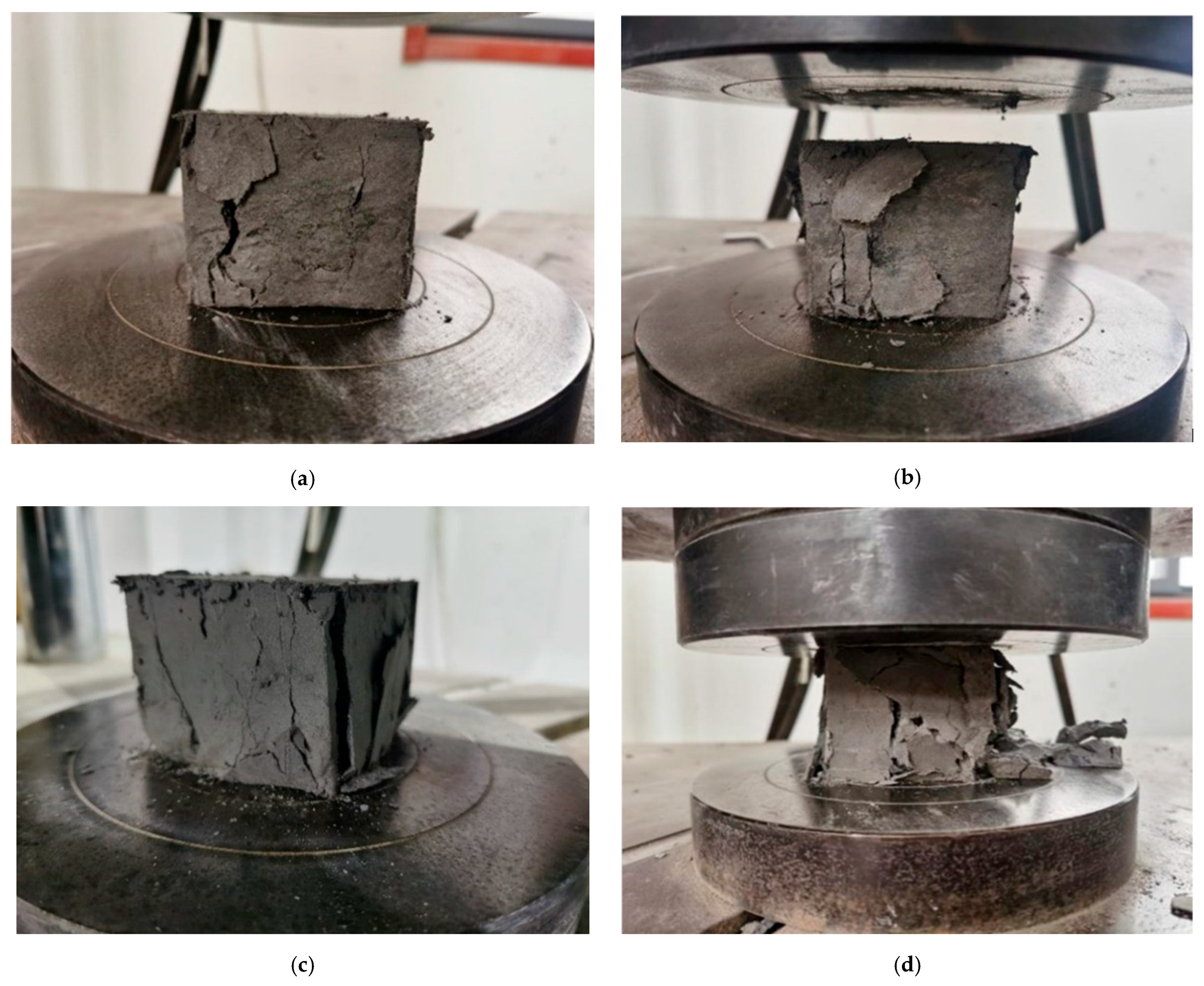
Observations of the destruction process of samples (using composition no. 4 as an example) based on curing time revealed a certain pattern (see Figure 3): with aging, the number of chips, delaminated particles, and cracks in the samples increased. At the same time, before complete failure, the samples at early stages of curing experienced significant deformations.
This observation allows the following conclusion: with an increase in curing time, the nature of destruction and deformation changes from ductile to brittle. This behavior was characteristic of all investigated compositions.
The strength development dynamics of cured samples of the investigated compositions, reinforced with glass fiber and nanomodified silicon dioxide in varying amounts, are shown in Figure 4.
The analysis of the strength development dynamics of samples tested under uniaxial compression during curing demonstrated an increase for all compositions compared to the reference (composition no. 1 based on cement binder). This indicates that reinforcing the backfill composite improves its strength characteristics, both in terms of curing dynamics and peak values. Composition no. 2, which was reinforced only with glass fiber, showed the best strength development dynamics, as confirmed by its linear dependence. All other compositions initially (up to 60 days) exhibited better strength development dynamics (compared to composition no. 2), but then, as evidenced by the flattening curves on the graphs, the strength development slowed down.
It is also important to note that the strength development dynamics of Samples Nos. 1, 2, 3, and 4 at the initial stage (up to 28 days) are practically the same. On day 60, there is a sharp increase (almost 2.5 times compared to the reference sample No. 1) in strength for composition no. 4, which contains both glass fiber and nano-modified silicon dioxide. By day 60, Samples Nos. 2 and 3 maintained the same strength development dynamics relative to each other but increased their rate by 1.5 times compared to the reference composition no. 1.
A possible reason for the slowed strength development during the initial stages of curing could be that a small amount of inhibitors (reinforcing components) in the formulation is insufficient to fully participate in the formation of a strong stone. That is, the amount of calcium silicate hydrate gel (C-S-H gel) formed in the early stages of the fly ash hydration process is not enough for the inhibitors to fully participate in forming the crystalline framework. Adding a greater amount of nano-modified silicon dioxide (composition no. 5) may accelerate the hydration reaction, leading to increased formation of calcium silicate hydrate gel (C-S-H gel), which in turn causes accelerated strength development.
However, for composition no. 5, where the dosage of nano-modified silicon dioxide was increased to 1% but glass fiber was excluded, the strength development dynamics become negative around day 90 (strength characteristics decrease). By about day 100 of curing, the strength characteristics of composition no. 5 are already lower than those of composition no. 4, which contains half the amount of nano-modified silicon dioxide but includes glass fiber. This conclusion aligns with previous research results on the reinforcement of backfill composites with various types of fibers.

3.2. Study in Splitting Mode

Similarly to the uniaxial compression test, the morphology of sample failure in the splitting mode (Figure 5) was studied during the strength development process, using samples of composition no. 3, which includes nano-modified silicon dioxide at a dosage of 0.5% as an inhibitor.
At the beginning of axial loading, the 7-day-old sample exhibited plastic characteristics, and small indentations formed on the upper and lower surfaces where the axial force was applied, without compromising the sample’s integrity. As loading continued, two cracks began to propagate from the upper surface and one from the lower surface. Further loading did not increase the length of the lower crack or the right upper crack, but the left crack on the upper part of the sample continued to widen and spread downward, eventually connecting with the lower crack. This led to a loss of the sample’s load-bearing capacity, resulting in failure. The right upper crack halted its development about one-quarter of the way into the sample (Figure 5a). After removing the sample from the stand, it broke into two parts.
In the axial splitting test of the 28-day-old sample, it was observed that the applied force did not cause plastic deformation. However, at the moment of loading, fine flaking occurred on the upper and lower surfaces of the sample that were in contact with the stand. Unlike the 7-day-old sample, the crack in this case began to develop only from the lower surface and, under axial force, spread to the upper surface, after which the sample lost its load-bearing capacity. The cracks originating from the upper surface in contact with the stand were barely visible (Figure 5b) and did not contribute to the sample’s failure. The width of the cracks in the 28-day-old sample was significantly narrower than those in the 7-day-old samples. After removal from the stand, the sample broke into two parts.
In the sample subjected to 60 days of curing, cracks, similar to those in the 28-day cured sample, began to form from the lower surface (Figure 5c). Although the crack did not visually extend to the upper surface, stopping its development at approximately 1/4 of the distance from the upper surface—meaning that there was no visible subvertical breach on the front surface—the sample lost its load-bearing capacity. This indicates that the internal structurally stable framework of the sample was compromised. The width of the cracks in this sample was even smaller than in the 28-day cured sample. After removal from the stand, the sample remained intact and did not disintegrate.
The sample with 120 days of curing exhibited a failure mode similar to that of the 60-day sample (Figure 5d): cracks formed and developed from the lower surface towards the upper surface; no visible subvertical breaches extended to the upper surface; and after removal from the stand, the sample remained intact without disintegrating. Unlike in all previous tests, during the loading process, characteristic cracking sounds were heard as the sample failed.
The results of failure tests in axial uniaxial splitting mode during strength development are presented in Figure 4.
The strength of axial uniaxial splitting during the strength development of the tested samples is expressed by a quadratic polynomial. The approximation coefficient R2 for any of the functions (i.e., for any composition) is above the value of 0.9491, which is the lowest and corresponds to the reference composition, which has the worst strength performance. As shown in Figure 4, the curves representing the relationship between the axial uniaxial splitting strength of the sample and its curing time tend to flatten out. Thus, increasing the curing time of the samples leads to a slowing of the rate of strength development in uniaxial splitting for all compositions.
Analysis of the graphs presented in Figure 6 reveals that the strength development dynamics for the control composition no. 1 (based on cement binder) and compositions no. 2 and no. 3 (based on fly ash binder with the addition of inhibitors: fiberglass and nanomodified silicon dioxide, respectively) exhibit a similar pattern up to approximately 90 days of curing. However, on the 90th day of curing, composition no. 2 (with fiberglass in the formulation) shows an increase in strength characteristics, albeit with a noticeable slowdown in the growth dynamics. In contrast, the control composition no. 1 exhibits no further strength growth. For composition no. 3 (with nanomodified silicon dioxide in the formulation), a negative trend is observed, indicating a decrease in strength characteristics after 90 days of curing.
Thus, it can be concluded that nanomodified silicon dioxide positively influences the rate of strength development in the early stages of curing, while fiberglass contributes to maintaining the strength development dynamics after approximately 90 days of curing. These results are fully consistent with the data obtained from the study of the compositions under uniaxial compression.
For composition no. 5 (with 1% nanomodified silicon dioxide in the formulation), there is a sharp increase in the axial uniaxial splitting strength characteristics. By the 28th day of curing, the samples reach 87% of their peak strength, and by the 60th day, they achieve 100%. After this period, strength development ceases.
Composition no. 4 demonstrated some intermediate results. The strength development dynamics of the samples containing 0.5% nanomodified silicon dioxide and 0.3% fiberglass were more consistent and correlated with the dynamics of the reference composition no. 1. However, around the 90th day of curing, a negative trend is observed, indicating a decrease in strength characteristics. At the same time, the rate of strength declines in axial uniaxial splitting for composition no. 4 is lower than that for composition no. 3, which did not contain fiberglass in its formulation.
The differences in strength characteristics between mixtures were interpreted based on trends consistently observed in validated batches. Although no formal statistical testing (e.g., p-values) was conducted, performance variations exceeding 25% between groups were treated as practically significant for the purposes of material optimization.
The backfill material is not exposed to freeze–thaw cycles in actual mining environments, as the air temperature in underground workings is regulated and maintained above +2 °C in accordance with occupational safety standards [72,73,74]. Therefore, freeze–thaw durability testing is not considered applicable [75]. However, long-term exposure to mine water and the leaching behavior of heavy metals remain important concerns [76,77]. Our research group has previously studied the impact of sulfate-rich mine waters on binder degradation [14,20,23,32,67], and future work will expand on heavy metal immobilization over time to assess environmental safety.
Fly ash properties can vary significantly by region, influencing long-term performance [71,78]. Although our samples retained strength beyond 90 days, future work will assess the effect of different fly ash sources on durability and subsidence risk in field conditions.

3.3. Microstructural Analysis

3.3.1. Influence of Nanomodified Silicon Dioxide

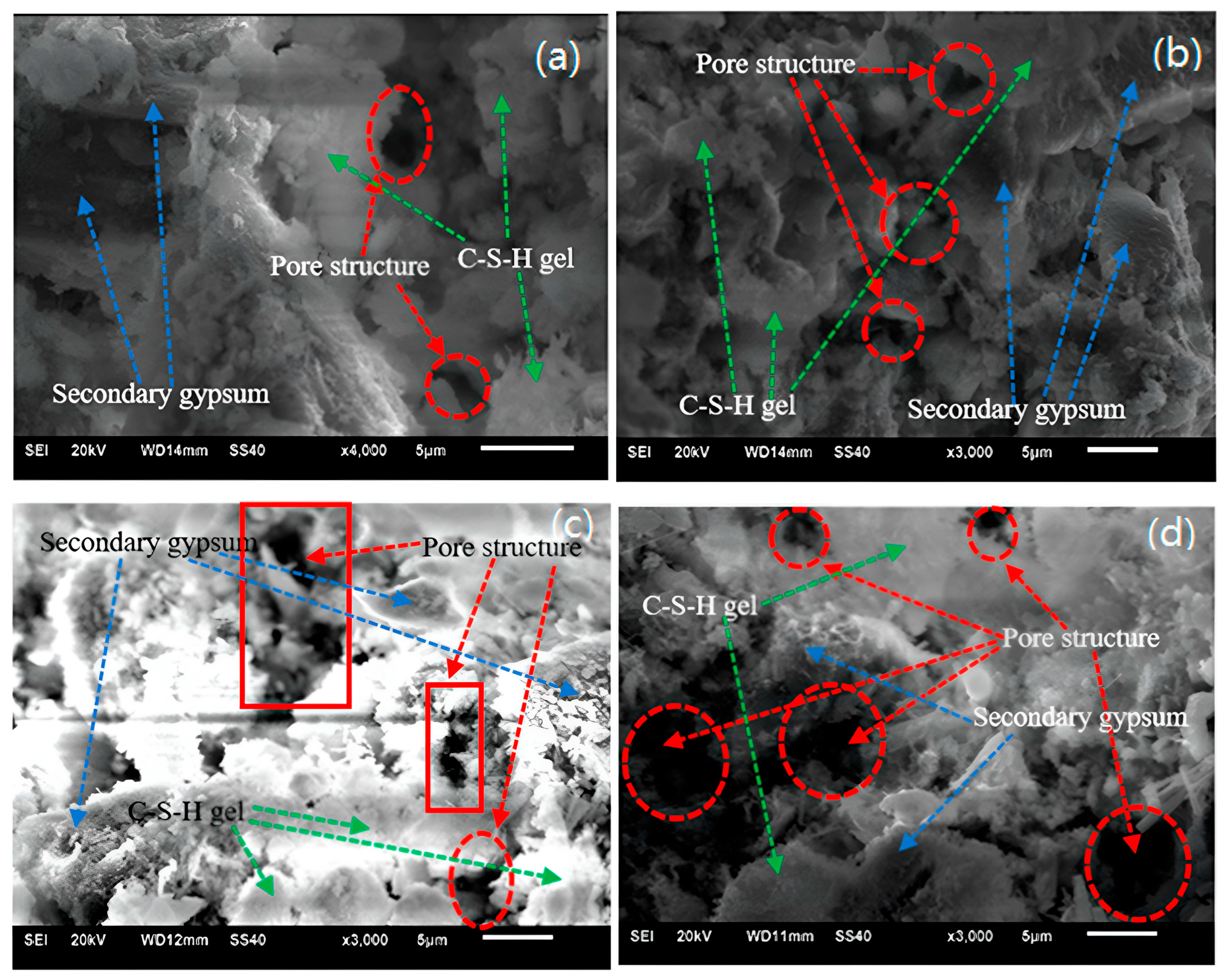
The scanning electron microscope (SEM) image presented in Figure 7 was obtained during the study of the microstructure of cured samples based on fly ash binder, incorporating 0.5% and 1.0% nanomodified silicon dioxide (compositions no. 3 and no. 5, respectively).
From the images in Figure 7, it is evident that regardless of the amount of nanomodified silicon dioxide, significant changes occur in the hydration products, as well as in the quantity and structure of pores, with increased curing time. Based on SEM morphology, the average pore size was estimated in the range of 5–20 µm. Literature on similar formulations suggests that fly ash-silica systems can form up to 25–35% C-S-H and N-A-S-H gels by volume [20,69]. For the 60-day-old sample no. 5, containing 1% nanomodified silicon dioxide (Figure 7b), the pore size and overall volume are significantly smaller than those of sample no. 3 with the same curing duration, which contains half the amount of silicon dioxide (Figure 7a). This explains the higher strength characteristics at the initial stages of curing (up to 60 days) for sample no. 5, where the increased amount of nanomodified silicon dioxide accelerates the hydration reaction, leading to increased formation of calcium silicate hydrate gel (C-S-H gel), which in turn results in a faster gain in strength. In Figure 5b, a greater number of C-S-H gel microaggregates and elongated cubic secondary gypsum can be identified compared to Figure 7a. In the 60-day-old structure of sample no. 5 (Figure 7b), the hydration products are observed throughout, lacking clear boundaries, indicating a denser structure and better cohesion.
As the curing time increases, moisture is removed, leading to air penetration into the pore space and an accelerated oxidation reaction. As seen in Figure 5c,d, the amount of secondary gypsum and C-S-H gel increases. For sample no. 3 (0.5% nanomodified silicon dioxide) with 120 days of curing, the space is relatively evenly filled with secondary gypsum and C-S-H gel products without distinct boundaries (Figure 7c). In contrast, sample no. 5 (1% nanomodified silicon dioxide) with 120 days of curing shows a “swelling” effect, indicating a less uniform and less dense structure (Figure 7d).
The expansion of the product and the growth of the swelling phase lead to an increase in pore space. While the pore volume increased only slightly for sample no. 3 (0.5% nanomodified silicon dioxide) with 120 days of curing (Figure 5c), it increased significantly in sample no. 5 (1.0% nanomodified silicon dioxide) with the same curing duration. A less dense structure indicates insufficient bonding between the hydration products and lower resistance to stress, which in turn leads to a decrease in the strength characteristics of the cured composite. This explains the significant drop in strength characteristics for sample no. 5.
Thus, the presence of a higher amount of nanomodified silicon dioxide in the backfill composite recipe accelerates hydration and the formation of secondary gypsum and C-S-H gel at the initial stages of curing, leading to a faster gain in strength up to 60 days of curing. However, with extended curing time, the accelerated formation of secondary gypsum after 90 days does not increase their quantity but rather their volume, thereby weakening the backfill composite. The introduction of oxygen into the newly formed pore space further reduces the C-S-H gel (Figure 7d), which further increases the porous structure within the composite, leading to a continued decline in mechanical properties.
Unlike Portland cement systems, the hydration of fly ash-based binders typically forms amorphous N-A-S-H and C-A-S-H gels, resulting from alkali-activated pozzolanic reactions. The formation of these gels plays a central role in strength development and pore refinement, as supported by recent studies [71].
Although this study was conducted under controlled laboratory conditions with a maximum curing period of 120 days, this timeframe aligns with industry norms, as most backfill mixtures reach 95–98% of their ultimate strength within this period. Moreover, our research team is currently performing extended experiments under simulated underground environments (e.g., elevated humidity, sulfate-containing mine waters, and confined conditions) to better approximate real mining settings. These additional studies are intended to validate the material’s long-term performance and environmental resistance under operational stresses.

3.3.2. Influence of Glass Fiber

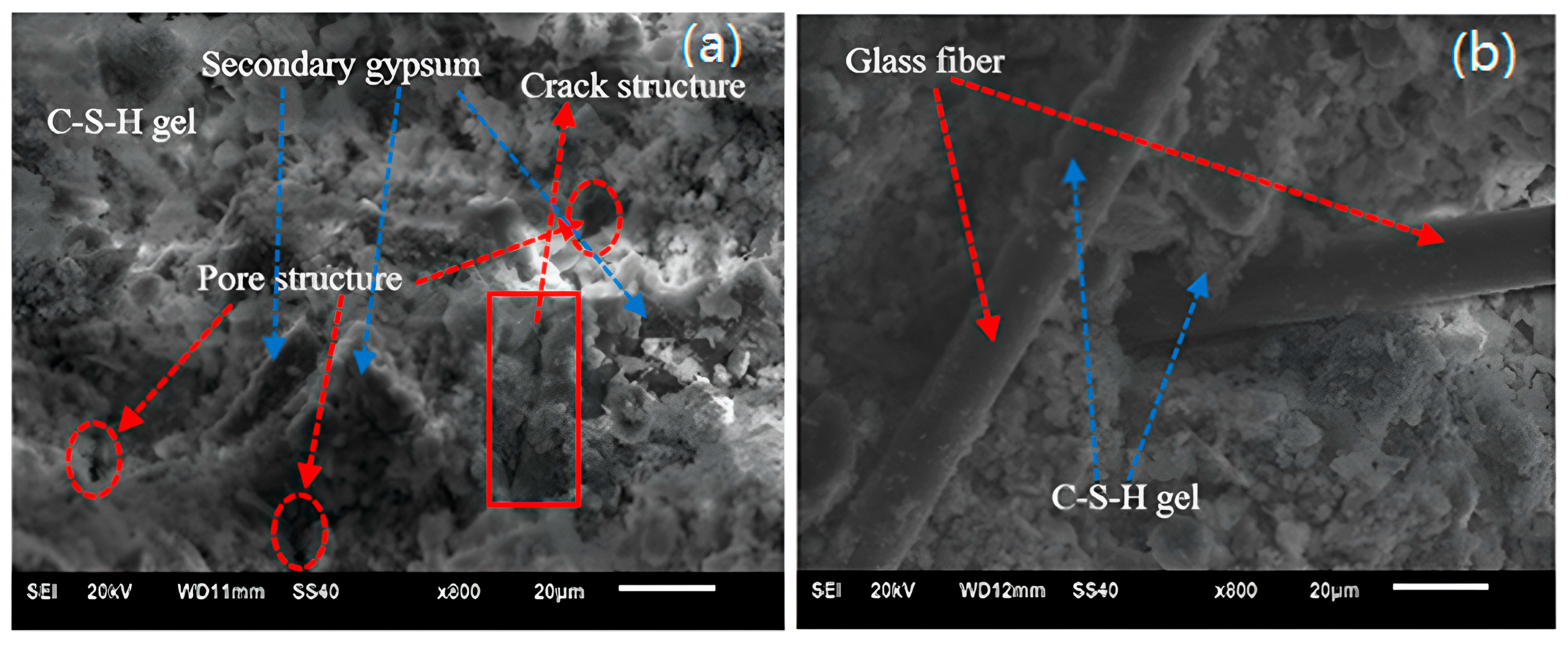
The effectiveness of glass fiber can be assessed by examining the microstructural analysis of the cured backfill composite and conducting a comparative analysis of compositions that include or exclude glass fiber (Figure 8).
In the 120-day-old samples of composition no. 3, which contains nanomodified silicon dioxide but lacks glass fiber, the formation of hydration products such as secondary gypsum and C-S-H gel is observed, along with noticeable pore structures and cracks (Figure 8a).
When glass fiber is introduced into the backfill composite recipe (composition no. 2, Figure 8b), the formation of C-S-H gel occurs on the surface of the fiber. However, the microstructural analysis of composition no. 2 did not reveal the presence of secondary gypsum in the matrix. The matrix formed during the cementation of fly ash, in the absence of secondary gypsum, is not capable of creating a structure with high mechanical characteristics. However, the C-S-H gel formed during hydration creates a strong adhesion with the contact surface of the glass fiber. Thus, the glass fiber binds the internal matrix structure of the cured composite into a cohesive whole, reinforcing it and thereby improving its mechanical properties.
This observation suggests that the fiber can effectively prevent the formation and expansion of pores and cracks, thereby enhancing the physical properties of the backfill composite created from the industrial waste of the coal industry.
Figure 9 shows images of the microstructural surface of backfill composite samples reinforced with glass fiber. The hydration products formed during curing disperse across the surface of the glass fiber and bond with it, creating a sufficiently strong adhesion (Figure 9b). The glass fiber weaves through the matrix of the backfill composite, creating a continuous connection between different sections of the matrix into a single monolithic framework, which significantly improves the mechanical properties.
Meanwhile, the introduction of nanomodified silicon dioxide into the formulation promotes the formation of compounds during hydration that effectively fill the voids (pores) between the glass fiber and the matrix of the cured backfill composite (Figure 9a). It can be observed that the hydrated materials and the formed matrix framework of the backfill composite containing nanomodified silicon dioxide adhere more closely to the glass fiber (Figure 9a) compared to the backfill composite where nanomodified silicon dioxide is absent from the formulation (Figure 9b). The reduction in the void space between the glass fiber and the matrix of the backfill composite enhances the bonding between them, which contributes to the increase in its mechanical properties during curing.
Future studies should employ XRF and SEM-EDS to provide a more comprehensive characterization of fly ash and waste rock compositions.

3.3.3. Environmental and System-Level Implications

Although this study did not include a full life cycle assessment, the environmental benefits of replacing cement with industrial waste such as fly ash are well documented. Prior studies have shown that using fly ash can reduce CO2 emissions associated with binder production by up to 80% [71]. The reuse of byproducts from coal combustion and glass manufacturing not only diverts waste from landfills but also minimizes the consumption of virgin raw materials.
Additionally, beyond the direct utilization of mining waste, the application of backfill systems allows for stress redistribution in the surrounding rock mass and helps maintain structural integrity in underground excavations. This, in turn, contributes to the minimization of ground surface degradation and the prevention of erosion-related processes [78], and leads to a reduction in the occurrence and development of water-conducting fractures [79], which is particularly critical for maintaining hydrogeological stability and ensuring mining safety in the exploitation of water-soluble ore deposits [80,81]. Comparative research has shown that such systems significantly reduce surface subsidence and can effectively eliminate soil erosion in backfilled areas [82,83].
A comprehensive carbon footprint analysis of the proposed mixtures, as well as predictive environmental modeling using approaches such as those outlined in [76], will be undertaken in future research to validate the long-term ecological benefits of the developed compositions under varying mining conditions.
Moreover, our research group has developed and applied an integrated model for assessing the efficiency of geo-resource processing systems across their full life cycle, with particular attention to environmental, economic, and technological criteria. A case study in the Russian mining sector confirmed the applicability of this model to optimize waste reutilization and sustainability planning in mineral processing operations [21].

4. Conclusions

  • The circular (closed-loop) economy predetermines the use and recycling of technogenic (man-made, industrial) waste.
  • The bench tests of the curing backfill composite, created from industrial waste from the coal industry, where crushed waste rock is used as an inert filler and traditional cement binder is replaced with fly ash, demonstrated the following results:
    2.1.
    Nanomodified silicon dioxide at a dosage of 0.5% in the backfill composite formulation increases both its mechanical properties and the curing rate at the initial storage periods.
    2.2.
    Increasing the curing time of the backfill composite with nanomodified silicon dioxide at a dosage of 0.5% leads to a gradual slowing of the growth of mechanical properties, followed by stabilization after 90 days.
    2.3.
    Doubling the content of nanomodified silicon dioxide from 0.5% to 1.0% in the backfill composite formulation leads to a sharp increase in its strength properties during the initial curing periods, followed by a decrease in the rate of strength development at 60 days and transitioning to negative values after 90 days.
    2.4.
    With increasing storage (curing) time, the nature of destruction and deformation changes from ductile to brittle.
    2.5.
    Glass fiber in the backfill composite formulation enhances its mechanical properties but does not affect the rate of strength development, demonstrating a stable growth rate.
    2.6.
    Simultaneous incorporation of glass fiber and nanomodified silicon dioxide into the backfill composite formulation results in a material with high strength characteristics, equalizes the rate of strength development throughout the storage period, and prevents the transition to negative values.
  • The microstructural analysis of the curing backfill composite, created from industrial waste from the coal industry, where crushed waste rock is used as an inert filler and traditional cement binder is replaced with fly ash, demonstrated the following results:
    3.1.
    With increasing curing time, nanomodified silicon dioxide in the backfill composite formulation leads to significant changes in the products of hydration, as well as in the quantity and structure of pores.
    3.2.
    Doubling the nanomodified silicon dioxide in the backfill composite formulation (from 0.5% to 1.0%) during the initial stages of curing promotes accelerated hydration and advanced formation of secondary gypsum and C-S-H gel.
    3.3.
    With increased curing time, the accelerated formation of secondary gypsum after 90 days leads to a weakening of mechanical properties due to the increase in the volumetric amount of secondary gypsum rather than its quantity.
    3.4.
    Glass fiber in the backfill composite binds the matrix structure, and the hydration products dispersed on the surface of the glass fiber adhere to it, forming a strong bond, which makes the matrix more durable.

Author Contributions

Conceptualization, M.M.K. and A.V.A., methodology, M.M.K. and T.N.K.; software and validation, O.Y.L. and G.V.K.; formal analysis and investigation, L.N.K., A.V.A. and M.A.L.; resources, T.N.K. and O.O.S.; data curation, O.Y.L. and L.N.K.; writing—original draft preparation, G.V.K. and M.A.L.; writing—review and editing, M.M.K. and O.O.S.; visualization, T.N.K. and L.N.K.; supervision and project administration, M.M.K. All authors have read and agreed to the published version of the manuscript.

Funding

This research received no external funding.

Data Availability Statement

No new data were created or analyzed in this study. Data sharing is not applicable to this article.

Conflicts of Interest

Author Marat M. Khayrutdinov was employed by the company Itasca Consultants GmbH, Leithestrasse Str. The remaining authors declare that the research was conducted in the absence of any commercial or financial relationships that could be construed as a potential conflict of interest.

References

  1. Babyr, N.V.; Gabov, V.V.; Nosov, A.A.; Nikiforov, A.V. Features of design and work method of mining module at coal deposits in the Russian Arctic. MIAB Min. Inf. Anal. Bull. 2024, 6, 5–16. (In Russian) [Google Scholar] [CrossRef]
  2. Petrenko, I.E. Russia’s coal industry performance for January–September, 2022. Ugol’ 2022, 12, 7–21. (In Russian) [Google Scholar] [CrossRef]
  3. Qiao, J.; Wang, Z.; Zhao, J. The evolution of thick coal seams mining methods in China. MIAB Min. Inf. Anal. Bull. 2020, 8, 105–117. [Google Scholar] [CrossRef]
  4. Babyr, N.V. Topical Themes and New Trends in Mining Industry: Scientometric Analysis and Research Visualization. Int. J. Eng. Trans. A Basics 2024, 37, 439–451. [Google Scholar] [CrossRef]
  5. Black, D.J. Review of coal and gas outburst in Australian underground coal mines. Int. J. Min. Sci. Technol. 2019, 29, 815–824. [Google Scholar] [CrossRef]
  6. Korshak, A.A.; Pshenin, V.V. Modeling of Water Slug Removal from Oil Pipelines by Methods of Computational Fluid Dynamics. Neft. Khozyaystvo—Oil Ind. 2023, 10, 117–122. [Google Scholar] [CrossRef]
  7. Kongar-Syuryun, C.B.; Sazankova, E.S.; Cherevko, M.A.; Dengaev, A.V. A study of the structural defects impact on the strength of rocks. Ugol 2025, 5, 97–100. (In Russian) [Google Scholar] [CrossRef]
  8. Li, M.; Yan, Y.; Dai, H.; Zhang, Z. Study on Rock and Surface Subsidence Laws of Super-High Water Material Backfilling and Mining Technology: A Case Study in Hengjian Coal Mine. Sustainability 2023, 15, 8713. [Google Scholar] [CrossRef]
  9. Kovalskiy, E.R.; Kongar-Syuryun, C.B.; Sirenko, Y.G.; Mironov, N.A. Modeling of rheological deformation processes for room and pillar mining at the Verkhnekamsk potash salt deposit. Sustain. Dev. Mt. Territ. 2024, 16, 1017–1030. (In Russian) [Google Scholar] [CrossRef]
  10. Rankine, R.; Pacheco, M.; Sivakugan, N. Underground Mining with Backfills. Soils Rocks 2007, 30, 93–101. [Google Scholar] [CrossRef]
  11. Esterhuizen, G.S.; Dolinar, D.R.; Ellenberger, J.L. Pillar strength in underground stone mines in the United States. Int. J. Rock Mech. Min. 2011, 48, 42–50. [Google Scholar] [CrossRef]
  12. Skrzypkowski, K. Decreasing Mining Losses for the Room and Pillar Method by Replacing the Inter-Room Pillars by the Construction of Wooden Cribs Filled with Waste Rocks. Energies 2020, 13, 3564. [Google Scholar] [CrossRef]
  13. Korshak, A.A.; Korshak, A.A.; Pshenin, V.V. Calculation of phase transitions in condensation units for recovery of oil and oil products vapors. Neft. Khozyaystvo—Oil Ind. 2021, 6, 98–101. [Google Scholar] [CrossRef]
  14. Kongar-Syuryun, C.B. Influence of mine water on the strength of artificial mass based on industrial waste. Ugol’ 2024, 12, 75–78. (In Russian) [Google Scholar] [CrossRef]
  15. Onyeneke, C.; Harper, B.; Thompson, S. Mining versus Indigenous Protected and Conserved Areas: Traditional Land Uses of the Anisininew in the Red Sucker Lake First Nation, Manitoba, Canada. Land 2024, 13, 830. [Google Scholar] [CrossRef]
  16. Skorobogatov, A.A.; Pshenin, V.V.; Tsvetkova, C.P.; Borisov, R.A. Multiphase Oil-water Flow in Horizontal and Inclined Pipelines. Effect of Flow Velocity on Flow Patterns. Int. J. Eng. Trans. B Appl. 2025, 38, 1820–1830. [Google Scholar] [CrossRef]
  17. Aznar-Sánchez, J.A.; García-Gómez, J.J.; Velasco-Muñoz, J.F.; Carretero-Gómez, A. Mining Waste and Its Sustainable Management: Advances in Worldwide Research. Minerals 2018, 8, 284. [Google Scholar] [CrossRef]
  18. Sharghi, M.; Jeong, H. The Potential of Recycling and Reusing Waste Materials in Underground Construction: A Review of Sustainable Practices and Challenges. Sustainability 2024, 16, 4889. [Google Scholar] [CrossRef]
  19. Soloviev, S.V.; Kuziev, D.A. Dragline ESH-10/70 linkage stiffness parameters study. Ugol’ 2017, 1, 37–38. [Google Scholar]
  20. Agafonov, V.V.; Oganesyan, A.S.; Solovykh, D.Y.; Kozlova, O.Y. Effect of polypropylene fiber on cement backfill based on tailings. Sustain. Dev. Mt. Territ. 2023, 15, 1108–1118. (In Russian) [Google Scholar] [CrossRef]
  21. Kongar-Syuryun, C.; Babyr, N.; Klyuev, R.; Khayrutdinov, M.; Zaalishvili, V.; Agafonov, V. Model for Assessing Efficiency of Processing Geo-Resources, Providing Full Cycle for Development—Case Study in Russia. Resources 2025, 14, 51. [Google Scholar] [CrossRef]
  22. Pawłuszek-Filipiak, K.; Wielgocka, N.; Rudziński, Ł. The Detectability of Post-Seismic Ground Displacement Using DInSAR and SBAS in Longwall Coal Mining: A Case Study in the Upper Silesian Coal Basin, Poland. Remote Sens. 2024, 16, 2533. [Google Scholar] [CrossRef]
  23. Tyulyaeva, Y.S.; Khayrutdinov, A.M. Creation of a backfill composite based on coal industry waste. Ugol’ 2024, 10, 24–27. (In Russian) [Google Scholar] [CrossRef]
  24. Tyulyaeva, Y.S.; Khayrutdinov, A.M.; Gorelkina, E.I. Increasing Classification of georesources in the paradigm of their integrated development. Russ. Min. Ind. 2024, 6, 140–143. (In Russian) [Google Scholar] [CrossRef]
  25. Gabov, V.V.; Babyr, N.V.; Zadkov, D.A. Mathematical modelling of operation of the hydraulic support system of the powered support sections with impulse-free continuous regulation of its resistance to the roof rock lowering. In IOP Conference Series: Materials Science and Engineering, Proceedings of the International Conference on Mechanical Engineering, Automation and Control Systems (MEACS 2020), Novosibirsk, Russia, 17 September 2020; IOP Publishing: Bristol, UK, 2021; Volume 1064. [Google Scholar] [CrossRef]
  26. Khairutdinov, M.M.; Shaimyardyanov, I.K. Underground geotechnology with backfilling: Shortcomings, opportunities for improvement. MIAB Min. Inf. Anal. Bull. 2009, 1, 240–250. (In Russian) [Google Scholar]
  27. Repin, S.V.; Afanasyev, A.S.; Dobromirov, V.N.; Barsukov, V.O. Innovative method for disposal of waste of monolithic building structures. Sustain. Dev. Mt. Territ. 2023, 15, 771–783. (In Russian) [Google Scholar] [CrossRef]
  28. Zakirova, G.S.; Pshenin, V.V.; Gustov, A.A. Compensation of Temperature Deformations of Gas Pipelines. Int. J. Eng. Trans. A Basics 2025, 38, 1699–1707. [Google Scholar] [CrossRef]
  29. Nikitin, V.I.; Nechaeva, O.A.; Zhivaeva, V.V. Software for calculating the volume of drilling fluid filtrate penetrating into the reservoir during well completion. Neft. Khozyaystvo—Oil Ind. 2022, 8, 126–128. [Google Scholar] [CrossRef]
  30. Afanasyev, A.S.; Egoshin, A.M.; Alekseev, S.V. Feasibility study of speed regulation on motor roads of mining operations. Russ. Min. Ind. 2025, 1, 82–87. (In Russian) [Google Scholar] [CrossRef]
  31. Klyuev, R.V.; Bosikov, I.I.; Majer, A.V.; Gavrina, O.A. Comprehensive analysis of the effective technologies application to increase sustainable development of the natural-technical system. Sustain. Dev. Mt. Territ. 2020, 12, 283–290. (In Russian) [Google Scholar] [CrossRef]
  32. Kongar-Syuryun, C.B.; Khayrutdinov, A.M.; Dengaev, A.V.; Abdulrahman, B. Research on the mechanical properties of backfill composite made from coal mining waste. Ugol’ 2025, 3, 145–148. (In Russian) [Google Scholar] [CrossRef]
  33. Cui, P.; Zhang, Q.; Yang, K.; Lv, H.; Cao, J.; Wang, W. Classification and Design of Backfill Coal Mining Systems Based on Typical Engineering Cases. Energies 2023, 16, 8074. [Google Scholar] [CrossRef]
  34. Avksentiev, S.Y.; Semenov, P.A.; Afanasev, A.S. Comprehensive solutions for tailings management at the Usolsky potash plant. Sustain. Dev. Mt. Territ. 2024, 16, 7–18. (In Russian) [Google Scholar] [CrossRef]
  35. Wang, S.; Ma, L. Characteristics and Control of Mining Induced Fractures above Longwall Mines Using Backfilling. Energies 2019, 12, 4604. [Google Scholar] [CrossRef]
  36. Korshak, A.A.; Gaisin, M.T.; Pshenin, V.V. Method of Structural Minimization of the Average Risk for Identification of Mass Transfer of Evaporating Oil at Tanker Loading. Neft. Khozyaystvo—Oil Ind. 2019, 10, 108–111. [Google Scholar] [CrossRef]
  37. Zhang, P.; Zhang, Y.; Zhao, T.; Tan, Y.; Yu, F. Experimental Research on Deformation Characteristics of Waste-Rock Material in Underground Backfill Mining. Minerals 2019, 9, 102. [Google Scholar] [CrossRef]
  38. Yu, Y.; Ma, L.; Zhang, D. Characteristics of Roof Ground Subsidence While Applying a Continuous Excavation Continuous Backfill Method in Longwall Mining. Energies 2020, 13, 95. [Google Scholar] [CrossRef]
  39. Denisov, E.F.; Yamilev, M.Z.; Tigulev, E.A.; Pshenin, V.V. Analysis of the current level of technologies for determining the location of non-metallic underground services. Neft. Khozyaystvo—Oil Ind. 2022, 9, 121–125. [Google Scholar] [CrossRef]
  40. Kovalsky, E.; Kongar-Syuryun, C.; Morgoeva, A.; Klyuev, R.; Khayrutdinov, M. Backfill for Advanced Potash Ore Mining Technologies. Technologies 2025, 13, 60. [Google Scholar] [CrossRef]
  41. Afanasyev, A.S.; Evtyukov, S.A.; Chudakova, N.V. Experimental study of the factors affecting the parameters of emergency braking process for vehicles of category M1. In IOP Conference Series: Materials Science and Engineering, Proceedings of the XIII International Scientific Conference on Architecture and Construction 2020, Novosibirsk, Russia, 22–24 September 2020; IOP Publishing: Bristol, UK, 2020; Volume 953, p. 12092. [Google Scholar] [CrossRef]
  42. Nikitin, V.I.; Agrelkina, M.M. Justification for the Selection of a Relative Permeability Model in the Task of Predicting Drilling Fluid Filtrate Invasion into the Formation. Int. J. Eng. 2025, 38, 2312–2320. [Google Scholar] [CrossRef]
  43. Wang, Y.; Huang, Y.; Hao, Y. Experimental Study and Application of Rheological Properties of Coal Gangue-Fly Ash Backfill Slurry. Processes 2020, 8, 284. [Google Scholar] [CrossRef]
  44. Xu, W.B.; Li, Q.L.; Tian, M.M. Strength and deformation properties of polypropylene fiber-reinforced cemented tailings backfill. Chin. J. Eng. 2019, 41, 1618–1626. [Google Scholar]
  45. Khayrutdinov, M.M.; Votyakov, M.V. Development of compositions of hardening stowing mixtures from ore processing wastes of potash enterprises. MIAB Min. Inf. Anal. Bull. 2007, 10, 220–222. [Google Scholar]
  46. Kongar-Syuryun, C.B. Industrial Waste in Backfill Composite—The Paradigm of Environmental and Process Safety during Field Development. Bezop. Tr. Promyshlennost 2025, 3, 73–78. [Google Scholar] [CrossRef]
  47. Nikitin, V.I.; Nechaeva, O.A.; Mozgovoi, G.S. Analysis of the results of the experiment to determine the saturation of the filtrate of drilling fluid of the core sample. In AIP Conference Proceedings, Proceedings of the III International Scientific Practical Conference “breakthrough Technologies and Communications in Industry and City” (BTCI 2020), Volgograd, Russia, 2–3 December 2020; AIP Publishing: Melville, NY, USA, 2021; Volume 2410, p. 20014. [Google Scholar] [CrossRef]
  48. Monteiro, M.; Santos, P.; Espinha Marques, J.; Flores, D.; Azenha, M.; Ribeiro, J.A. Assessment of Potential Environmental Risks Posed by Soils of a Deactivated Coal Mining Area in Northern Portugal—Impact of Arsenic and Antimony. Pollutants 2025, 5, 15. [Google Scholar] [CrossRef]
  49. Stadnik, D.A. Objectives of functional subsystems within the unified industrial system automated design of coal mines. Ugol’ 2017, 10, 52–56. [Google Scholar] [CrossRef]
  50. Terrones-Saeta, A.; Terrones-Saeta, J.M.; Suárez-Macías, J.; Iglesias-Godino, F.J.; Corpas-Iglesias, F.A. Development and Mechanical Analysis of Geopolymers Formed with Mining Residue and Fly Ash from Municipal Solid Waste Incineration Obtained After the Neutralisation Stage. Polymers 2025, 17, 1704. [Google Scholar] [CrossRef]
  51. Sáez-Navarrete, C.; Baraza, X.; Ramos-Grez, J.; Sans, C.; Arauzo, C.; Coca, Y. Laser-Induced Surface Vitrification for the Sustainable Stabilization of Copper Tailings. Sustainability 2025, 17, 5676. [Google Scholar] [CrossRef]
  52. Nikitin, V.I.; Zhivaeva, V.V.; Nechaeva, O.A.; Kamaeva, E.A. Influence of capillary pressure on the restoration of the bottomhole zone permeability at the filtrate-oil interfacial phase. In Topical Issues of Rational Use of Natural Resources; CRC Press: Boca Raton, FL, USA, 2019; pp. 558–562. [Google Scholar] [CrossRef]
  53. Cao, H.; Wang, A.; Yilmaz, E.; Cao, S. Machine Learning Algorithm-Based Prediction Model and Software Implementation for Strength Efficiency of Cemented Tailings Fills. Minerals 2025, 15, 405. [Google Scholar] [CrossRef]
  54. Jastrzębska, M.; Kazimierowicz-Frankowska, K.; Chiaro, G.; Rybak, J. New Frontiers in Sustainable Geotechnics. Appl. Sci. 2023, 13, 562. [Google Scholar] [CrossRef]
  55. Nikitin, V.I. Problem solution analysis on finding the velocity distribution for laminar flow of a non-linear viscous flushing fluid in the annular space of a well. J. Min. Inst. 2022, 258, 964–975. [Google Scholar] [CrossRef]
  56. Marimuthu, M.; Krishnan, V.; Sudhakaran, S.D.; Vigneswari, S.; Senthilkumar, S.; Veerapandian, M. Electrochemical-Based Biosensor Platforms in Lab-Chip Models for Point-of-Need Toxicant Analysis. Electrochem 2023, 4, 537–552. [Google Scholar] [CrossRef]
  57. Đurđevac, V.; Staletović, N.; Ignjatović, L.Đ.; Jovanović, V.; Vuković, N.; Krstić, V. Application of Flotation Tailings as a Substitute for Cement in Concrete Structures for Environmental Protection and Sustainable Development—Part I: Sulfide Neutralization. Materials 2025, 18, 2804. [Google Scholar] [CrossRef]
  58. Elokhova, I.; Vyatkin, K.; Ilyushin, P.; Krutova, A.; Pepelyaeva, A.; Sliusar, N. Evaluating the Eco-Intensity Dynamics of the Mining Industry in Russia: Towards a Circular Economy. Recycling 2023, 8, 31. [Google Scholar] [CrossRef]
  59. Abdulkadir, S.B.; Chen, Q.; Yilmaz, E.; Wang, D. Comparative and Meta-Analysis Evaluation of Non-Destructive Testing Methods for Strength Assessment of Cemented Paste Backfill: Implications for Sustainable Pavement and Concrete Materials. Materials 2025, 18, 2888. [Google Scholar] [CrossRef]
  60. Zhang, Z.-X. Lost-ore mining—A supplementary mining method to sublevel caving. Int. J. Rock Mech. Min. Sci. 2023, 168, 105420. [Google Scholar] [CrossRef]
  61. GOST 5802-86; Cements. Methods for Determination of True Density. State Committee for Standards of the USSR: Moscow, Russia, 1986.
  62. GOST 10180-2012; Concretes. Methods for Strength Determination Using Control Specimens. Standartinform: Moscow, Russia, 2012.
  63. Li, Z.; Yin, D.; Jiang, N.; Wang, F.; Ding, Y.; Li, F. Deformation and Failure Characteristics of Bimaterial Samples Consisting of Sandstone and Cemented Coal Gangue–Fly Ash Backfill under Uniaxial Loading. Minerals 2022, 12, 1546. [Google Scholar] [CrossRef]
  64. Egoshin, A.M.; Afanasyev, A.S.; Alekseev, S.V. Procedure of mineral delivery system selection based on economic analysis of alternatives. MIAB Min. Inf. Anal. Bull. 2024, 6, 135–148. (In Russian) [Google Scholar] [CrossRef]
  65. Komokhov, P.G.; Kharitonov, A.M. Nanostructural model of cement stone for assessing the properties of a composite material. Pop. Concr. Sci. 2007, 2, 125–127. [Google Scholar]
  66. Hanehara, S.; Ichikawa, M. Nanotechnology of cement and concrete. Taiheiyo Cem. Kenkyu Hokoku 2001, 141, 47–58. [Google Scholar]
  67. Tyulyaeva, Y.S.; Khayrutdinov, A.M.; Galachieva, I.D.; Totrukova, I.K. Creation of a high-strength backfill composite based on sulfide-bearing technogenic waste from mining production. Sustain. Dev. Mt. Territ. 2024, 16, 1384–1396. (In Russian) [Google Scholar] [CrossRef]
  68. Khetagurov, V.N.; Kamenetsky, E.S.; Gegelashvili, M.V.; Marzoev, A.T. Granulometric composition study of fine product obtained by dolomite grinding in a centrifugal mill of Vertical type. Sustain. Dev. Mt. Territ. 2024, 16, 197–204. (In Russian) [Google Scholar] [CrossRef]
  69. Aleksakhin, A.; Sala, D.; Golovin, K.; Kovalev, R. Reducing energy costs for pipeline transportation. Transp. Res. Procedia 2021, 57, 24–32. [Google Scholar] [CrossRef]
  70. Fedorov, G.B.; Dudchenko, O.L.; Kurenkov, D.S. Development of vibroacoustic module for fine filtration of drilling muds. J. Min. Inst. 2018, 234, 647–651. [Google Scholar] [CrossRef]
  71. Provis, J.L.; van Deventer, J.S.L. Alkali-Activated Materials: State of the Art Report, RILEM TC 224-AAM; Springer: Dordrecht, The Netherlands, 2014. [Google Scholar] [CrossRef]
  72. Kropachev, A.N.; Podrezov, S.V.; Aleksakhin, A.V.; Gudilin, A.A.; Kondratyeva, O.A.; Korshunova, L.N. Thermodynamic Studies and Optimization of the Method for Obtaining Neodymium Fluoride for the Production of Magnetic Sensors’ Sensitive Elements. Sensors 2021, 21, 8361. [Google Scholar] [CrossRef] [PubMed]
  73. Melnik, V.V.; Efimov, V.I.; Korchagina, T.V.; Popov, A.I.; Muzafarov, G.G. Experience of steeply dipping coal seam mining. MIAB Min. Inf. Anal. Bull. 2018, 11, 18–38. [Google Scholar]
  74. Vasyuchkov, Y.F.; Melnik, V.V. Mining of coal deposit on the base of “Local coal gas electric complexes”. Eurasian Min. 2017, 2, 20–24. [Google Scholar] [CrossRef][Green Version]
  75. Zhang, Z.; Zhang, F.; Wu, C.; Chen, Y. Experimental Study on the Performance of Sustainable Epoxy Resin-Modified Concrete Under Coupled Salt Corrosion and Freeze–Thaw Cycles. Sustainability 2025, 17, 6186. [Google Scholar] [CrossRef]
  76. Shinkevich, A.I.; Kostyukhin, Y.Y.; Savon, D.Y.; Safronov, A.E.; Aleksakhin, A.V. Optimization of Energy-Efficient Functioning of the Oil and Gas Sector of the Economy through Digitalization and Resource Conservation. Int. J. Energy Econ. Policy 2021, 11, 321–330. [Google Scholar] [CrossRef]
  77. Novoselov, S.V.; Melnik, V.V.; Agofonov, V.V. Year of ecology in Russia and approaches to resolving geoecological problems in Kuzbass. Ugol 2017, 3, 78–79. [Google Scholar] [CrossRef][Green Version]
  78. Gusev, V.N.; Odintsov, E.E.; Zherlygina, E.S. Calculation of Displacements and Deformations in Rock Mass with Regard to Field Data. Gornyi Zhurnal 2025, 18–25. [Google Scholar] [CrossRef]
  79. Odintsov, E.E.; Gusev, V.N. Rock Mass Condition Control by the Method of Predicting of Water-Conducting Fracture Zone Parameters for the Deposits of Polymetallic Ores. Int. J. Eng. Trans. C Aspects 2025, 39, 1326–1333. [Google Scholar] [CrossRef]
  80. Stadnik, D.A.; Stadnik, N.M.; Grigoryan, K.L.; Kozhiev, Z.V. Technological Updating of Mineral Mining Projects Using Computer Technologies. MIAB Min. Inf. Anal. Bull. 2023, 2023, 170–184. (In Russian) [Google Scholar] [CrossRef]
  81. Stadnik, D.A.; Stadnik, N.M.; Zhilin, A.G.; Lopushnyak, E.V. Methodological Framework for Implicit Modeling of Solid Mineral Deposits in Automated Design. MIAB Min. Inf. Anal. Bull. 2023, 2023, 185–197. (In Russian) [Google Scholar] [CrossRef]
  82. Tian, H.; Zhao, Y.; Xie, J.; Fan, G.; Zhao, Y.; Zhang, N. Life-Cycle Assessment of Backfill Paste Using Fly-Ash and Tailings. Resour. Policy 2019, 64, 101449. [Google Scholar] [CrossRef]
  83. Attom, M.F.; Vandanapu, R.; Khan, Z.; Yamin, M.; Astillo, P.V.; Eltayeb, A.; Khalil, A. Prediction of Internal Erosion Parameters of Clay Soils Using Initial Physical Properties. Water 2024, 16, 232. [Google Scholar] [CrossRef]
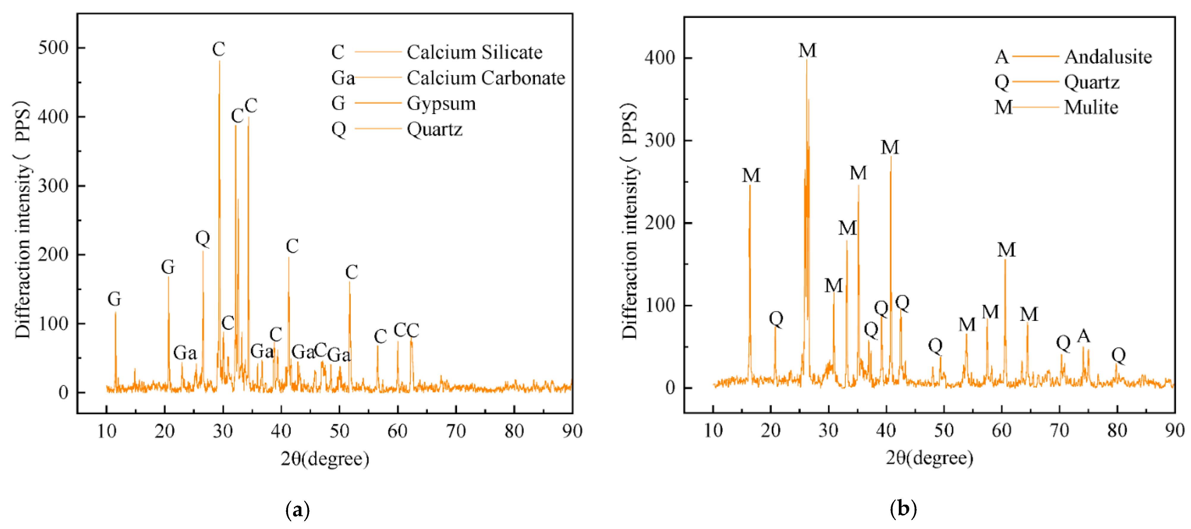
Figure 1. X-ray diffraction patterns: (a) cement; (b) fly ash.
Mining 05 00057 g001
Figure 2. X-ray diffraction pattern of waste rock from the “im. Lenina” mine. The collected samples of waste rock were crushed in a jaw crusher to a size of no more than 20 mm.
Mining 05 00057 g002
Figure 3. Observation of fracture morphology under uniaxial compression in strength development dynamics (example of composition no. 4): (a) 7th day; (b) 28th day; (c) 60th day; (d) 120th day.
Mining 05 00057 g003
Figure 4. Strength development dynamics of cured samples with different formulations.
Mining 05 00057 g004
Figure 5. Observation of failure morphology in axial uniaxial splitting mode during strength development (based on composition no. 4): (a) 7th day; (b) 28th day; (c) 60th day; (d) 120th day.
Mining 05 00057 g005
Figure 6. Axial Uniaxial Splitting Strength Characteristics for Different Compositions Over Curing Time.
Mining 05 00057 g006
Figure 7. Microstructure of samples depending on the amount of nanomodified silicon dioxide and curing time: (a) 0.5% Nano-SiO2 60 days; (b) 1% Nano-SiO2 60 days; (c) 0.5% Nano-SiO2 120 days; (d) 1% Nano-SiO2 120 days.
Mining 05 00057 g007
Figure 8. Microstructural image of the cured backfill composite after 120 days of storage: (a) composition no. 3 (with Nano-SiO2); (b) composition no. 2 (with glass fiber).
Mining 05 00057 g008
Figure 9. Microstructural image of the cured backfill composite with a 120-day storage period: (a) composition no. 4 (with Nano-SiO2); (b) composition no. 2 (without Nano-SiO2).
Mining 05 00057 g009
Table 1. Program for selecting the backfill composite formulation.
No.ComponentWaste RockCementFly AshGlass FiberNano-SiO2
1%991000
2%65034.500.5
3%65034.70.30
4%65034.20.30.5
5%65033.701.0
Table 2. Characteristics of nanomodified silicon dioxide.
TypeSurface AreaBulk DensityDensityCrystalline TypeColorPurity
Nano-SiO2240 m2/g0.06 g/cm32.2~2.6 g/cm3Spherical ShapeWhite≥99.99%
Table 3. Characteristics of glass fiber used as a reinforcing material.
TypeDiameter (µm)Length (mm)Tensile Strength (MPa)Modulus of Elasticity (GPa)Density (g/cm3)Elongation at Break (%)
fiberglass1963694.8269936.5
Disclaimer/Publisher’s Note: The statements, opinions and data contained in all publications are solely those of the individual author(s) and contributor(s) and not of MDPI and/or the editor(s). MDPI and/or the editor(s) disclaim responsibility for any injury to people or property resulting from any ideas, methods, instructions or products referred to in the content.