Abstract
The exploration of Pb-Zn mineralization in carbonate complexes during field campaign is a challenging process that consumes high expenses and time to discover high prospective zones for a detailed exploration stage. In this study, multi-sensor remote-sensing imagery from Landsat-8, Sentinel-2, and ASTER were utilized for Pb-Zn mineralization prospectivity mapping in the Akhlamad carbonate complex area, Razavi Khorasan, NE Iran. Due to the presence of carbonate formations and various evidence of Pb-Zn mineralization, this area was selected. Band composition, band ratio, principal component analysis (PCA), and SAM techniques for mapping alteration minerals as well as lineament analysis were implemented. Subsequently, a fuzzy logic model for identifying the prospective zones of Pb-Zn mineralization using multi-sensor remote-sensing satellite images was designed. The weight of each exploratory layer was determined using the fuzzy hierarchical method and the integration process of the information layers was performed using fuzzy operators. Finally, the existing mineral indications were used to evaluate and validate the obtained mineral potential map. The outcome of this investigation suggested several high-potential zones for Pb-Zn exploration in the study area.
Keywords:
ASTER; Landsat-8; Sentinel-2; PCA; SAM; fuzzy logic modeling; prospectivity mapping; Pb-Zn mineralization 1. Introduction
The hydrothermal fluids associated with ore mineralization alter the mineralogy and chemistry of the host rocks and generate typical mineral assemblages containing specific spectral features, which can be detected using spectral remote-sensing sensors [1,2,3]. The major types of alteration mineral zones such as phyllic, argillic, propylitic, and gossan are typically found in most metallogenic provinces [3,4,5]. Remote-sensing satellite imagery can play an effectual role in distinguishing the demonstrative minerals for the various alteration zones. In recent decades, a new generation of advanced remote-sensing sensors has been used for lithological mapping, mineral exploration, and environmental geology [5,6,7]. The progress of remote-sensing image-processing techniques has made it possible to provide comprehensive information about the mineralogy of the diverse types of rocks on the Earth’s surface [8,9,10].
Landsat sensors (e.g., Landset-7) were used to detect hydrothermal alteration zones using image-processing methods such as false color composite (FCC), band ratio (BR), and principal component analysis (PCA) [11]. Landsat-8 collects images for nine visible, near-infrared (VNIR) and shortwave infrared (SWIR) bands (termed the Operational Land Imager (OLI)) and two long-wave thermal bands (named the Thermal Infrared Sensor (TIRS). The OLI images have been successfully utilized for many geological and mineral exploration studies [12,13,14,15,16,17,18,19,20]. The use of ASTER datasets for detecting alteration minerals has successfully continued owing to its broad coverage and unique integral bands, which are highly subtle to alteration minerals [21,22,23]. The VNIR bands (0.52 to 0.86 µm; spatial resolution of 15 m) can distinguish iron-bearing minerals (iron oxides/hydroxides) [24]. Six spectral bands in the SWIR range (1.60 to 2.43 μm; ground resolution of 30 m) differentiate and map the alteration of clay and carbonates, hydroxides, and hydrous minerals [25,26,27]. Various image-processing algorithms such as relative absorption band depth (RBD), principal component analysis (PCA), spectral angle mapping (SAM), band ratio (BR), Matched-Filter (MF), Mixture-Tuned Matched-Filtering (MTMF), Linear Spectral Unmixing (LSU), and Constrained Energy Minimization (CEM) were successfully implemented to ASTER bands to obtain accurate mineralogical information from the lithological background [10,28,29,30,31,32,33,34,35,36]. Sentinel-2 contains 13 spectral bands in the VNIR and SWIR regions (0.433 to 2.2890 μm; spatial resolution 10 to 60 m), which are suitable for identifying iron oxides/hydroxides and minerals containing hydroxyl [37,38,39]. The band ratios of Sentinel 2 data were used for mapping iron absorption features associated with gossan and dolomitization [26,39,40,41]. Accordingly, several processing procedures have been used for identifying the boundaries of lithological units, weathered areas, and hydrothermally altered rocks. The application of multispectral image-processing methods can be effective in detecting and tracing possible mineralization around carbonate veins containing Pb-Zn mineralization [42,43].
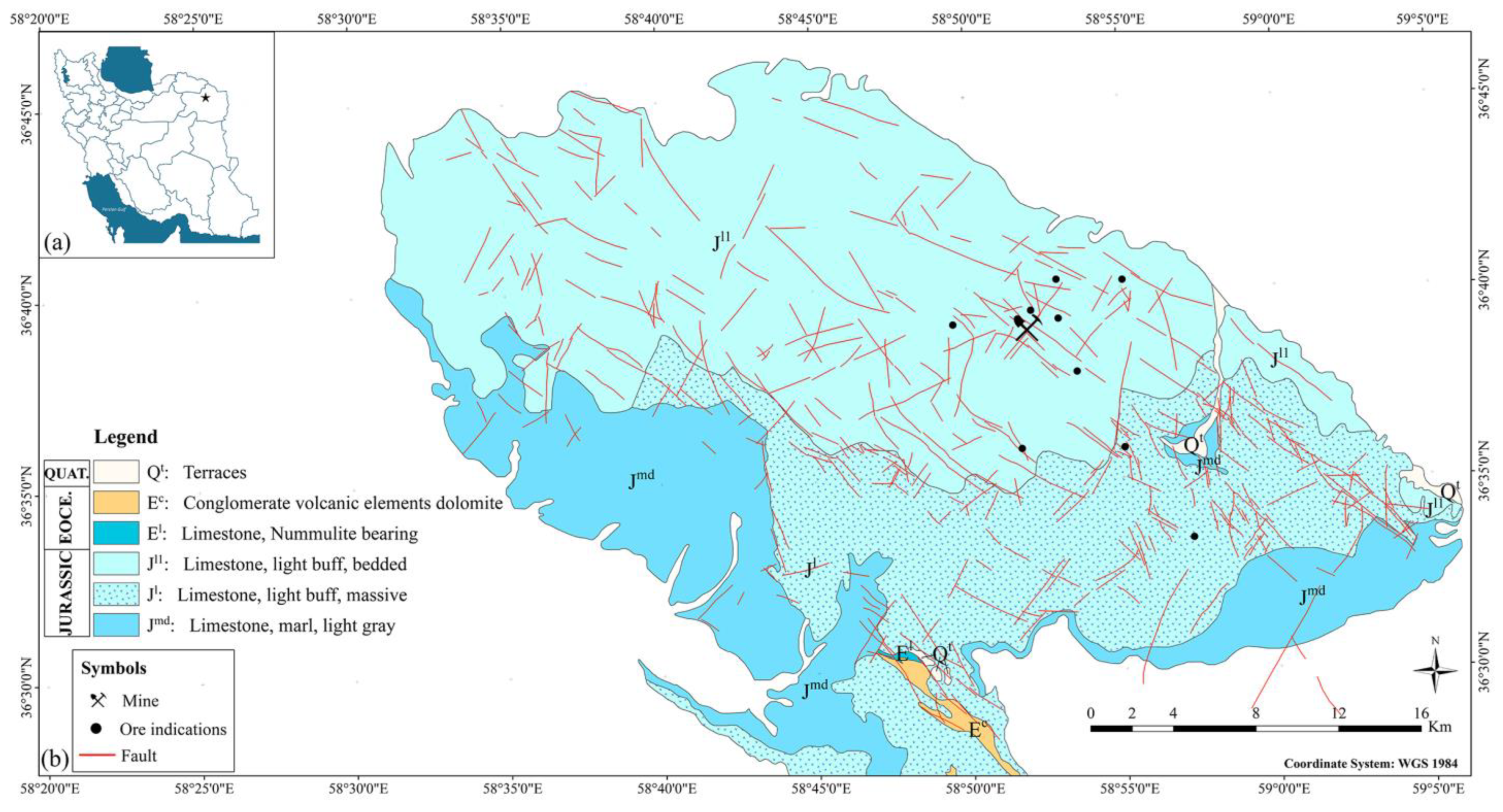
The significant Pb-Zn metallogenic provinces in Iran, namely the Sanandaj–Sirjan zone, Central Iran zone, and Alborz zone, showed the age of host rock mineralization from upper Proterozoic to Oligocene–Miocene [44,45]. Some remote-sensing studies were conducted in the Gujer non-sulfide Zn deposit in the west of the Ravar city in Kerman, Pb–Zn SEDEX mineralization in the Behabad area in Central Iran, and carbonate-hosted Pb-Zn deposits in the Kashmar–Kerman tectonic zone, which confirmed the application of remote-sensing techniques for Pb-Zn exploration [12,13,14,26]. The study area selected in this investigation is located in the Binalud zone, Razavi Khorasan, NE Iran (Figure 1), which is a part of the Alborz collision belt. The Binalud zone is located in the south of the contact line between Iran and Turan plates [46,47,48]. It was constructed during the closing of the Paleo-Tethys besides the collision of the Turan plate and a lithospheric segment of Iran [47,49]. The fold and thrust belt contains an NW-SE direction and comprises various rocks and sediments detached from fault boundaries. The presence of carbonate formations and various evidence of Pb-Zn mineralization was documented in this area [44,45]. The accurate mapping of alteration mineral zones (e.g., gossan and dolomitization) associated with Pb-Zn mineralization in carbonate host rock is one of the essential factors for Pb-Zn exploration in the Binalud zone. However, there is still no inclusive remote-sensing study to accurately identify and map alteration mineral zones, lithological units, and structural features for Pb-Zn exploration in the Akhlamad area, the Binalud zone. In this research, multi-sensor remote-sensing imagery, including Landsat-8, Sentinel-2, and ASTER satellite remote-sensing data were used to map alteration mineral zones, lithological units, and structural features associated with Pb-Zn exploration in the Akhlamad area, the Binalud zone. Therefore, the main objectives of this study are: (i) to extract spectral information from Landsat-8, Sentinel-2, and ASTER image spectra at the pixel level for mapping alteration minerals and lithological units using band ratios, PCA, and SAM image-processing algorithms; (ii) to extract lineament features from Landsat-8, Sentinel-2, and ASTER image using edge detection models, and applying different filters; and (iii) to fuse the alteration and lineament thematic layers for generating Pb-Zn mineralization prospectivity map using fuzzy logic modeling.
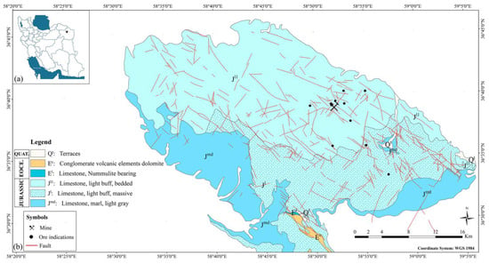
Figure 1.
(a) The geographical location of the study area showing with star in north east of Iran. (b) A simplified geologic map of the study area. Pb-Zn mineralization points in the study area are shown using star symbols.
2. Geological Setting
The Binalud mountains split Central Iran from eastern Kopeh Dagh as an asymmetric antiformal range. The geological structures generated from Paleo-Tethys closure experienced ductile and brittle tectonic deformation stages [48]. The mountains experienced contractional deformation during the Cenozoic together with the adjacent regions (the Kopeh Dagh and AllahDagh mountains) [50]. The Akhlamad basin is located in the northern part of the heights of Binalud in the Khorasan Razavi province (Figure 1a). It is situated about 45 km NE of Mashhad city. In terms of basin divisions, Akhlamad is considered one of the sub-basins of the Kashf Roud watershed. The studied area was limited from the east to the watershed area of the Frizi River, from the west to the Baze Sarhesar River, and from the south to the heights of Marghzar and Kalate Dargah. The Akhlamad region is located between latitudes 36°30′0″ and 36°40′0″ north and longitudes 58°51′0″ and 59°2′25″ east. A simplified geologic map of the Akhlamad region is shown in Figure 1b.
The formations exposed in the study area are owned by the middle Jurassic to late Jurassic, including Jmd (equivalent Dalichay formation), Jl and Jl1 (equivalent Lar formation), and limestones. The Jmd rock units consist of dark coaly shales, gray thin-bedded micritic limestone with the intercalation of green to gray shale. The Jl and Jl1 rock units consist of thick-bedded limestone with the intercalation of light gray to green shale. Faults with NW-SE and NE-SW trends and folds with NW-SE trends are the major structural features in the area. In this area, the limestone and dolomite masses are mostly stony and form high to low altitudes that are enclosed by recent covenant alluviums. Pb-Zn deposits occurred in Cretaceous carbonate host rocks in this area, which are classified as Mississippi Valley-Type (MVT) deposits. Pb-Zn deposits are hosted with various types of Cretaceous dolostone and limestone. Dolostones typically contain the replacement of dolomite with minor dolomite cements. The Pb-Zn deposits are associated with tensional faults and fractures as strata-bound veins and breccia type in karstic and tectonic breccias. Galena with minor sphalerite and pyrite are hypogene minerals. Fe-oxide, cerussite, anglesite, plattnerite, minium, and mimetite are supergene minerals. Calcite, quartz, and dolomite are considered gangue minerals [51].
3. Materials and Methods
3.1. Remote-Sensing Data Characteristics
In this study, Landsat-8, Sentinel-2, and ASTER were utilized. The technical characteristics of ASTER, Landsat-8, and Sentinel-2 datasets are shown in Table 1. The datasets were processed to identify lithological units and alteration zones; structural features; and the mapping of carbonate, clay, dolomitization, and iron oxide/hydroxide minerals. A Landsat-8 scene (LC08_L1TP_160035_20130718_20200912_02_T1, Path/Raw: 160/035) and an ASTER scene (AST_L1B_00310062003073157_20080708131228_1829) covering the study area were obtained from the U.S. Geological Survey Earth Resources Observation and Science (EROS) Center (https://www.usgs.gov/centers/eros (accessed on 18 July 2023). A Sentinel-2A scene (S2B_MSIL1C_20220831T064629_N0400_R020) covering the study area was acquired from the European Space Agency (Copernicus Open Access Hub; https://scihub.copernicus.eu/ (accessed on 18 July 2023).

Table 1.
The technical characteristics of ASTER, Landsat-8, and Sentinel-2 datasets.
The Level 1 terrain-corrected (L1T) products of Landsat-8 and ASTER have been already georeferenced to the UTM zone 40 north projection using the WGS84 datum. The Sentinel-2A used in this analysis is a Level-1C top-of-atmosphere (TOA) reflectance (100 km × 100 km tile) product, which contains radiometric and geometric corrections (UTM zone 40 north projection with WGS84 datum) with orthorectification. Raw digital satellite data typically contain geometric distortions due to sensor geometry, scanner, platform instabilities, earth rotation, earth curvature, etc., and it is necessary to correct and adapt them [52]. The Fast Line-of-sight Atmospheric Analysis of Spectral Hypercube (FLAASH) algorithm was applied for the atmospheric correction of the datasets [52]. In this research, for image processing the remote-sensing data, ER-Mapper version 7, ENVI 5.3, and ArcGIS 10.8 software were used.
3.2. Methods
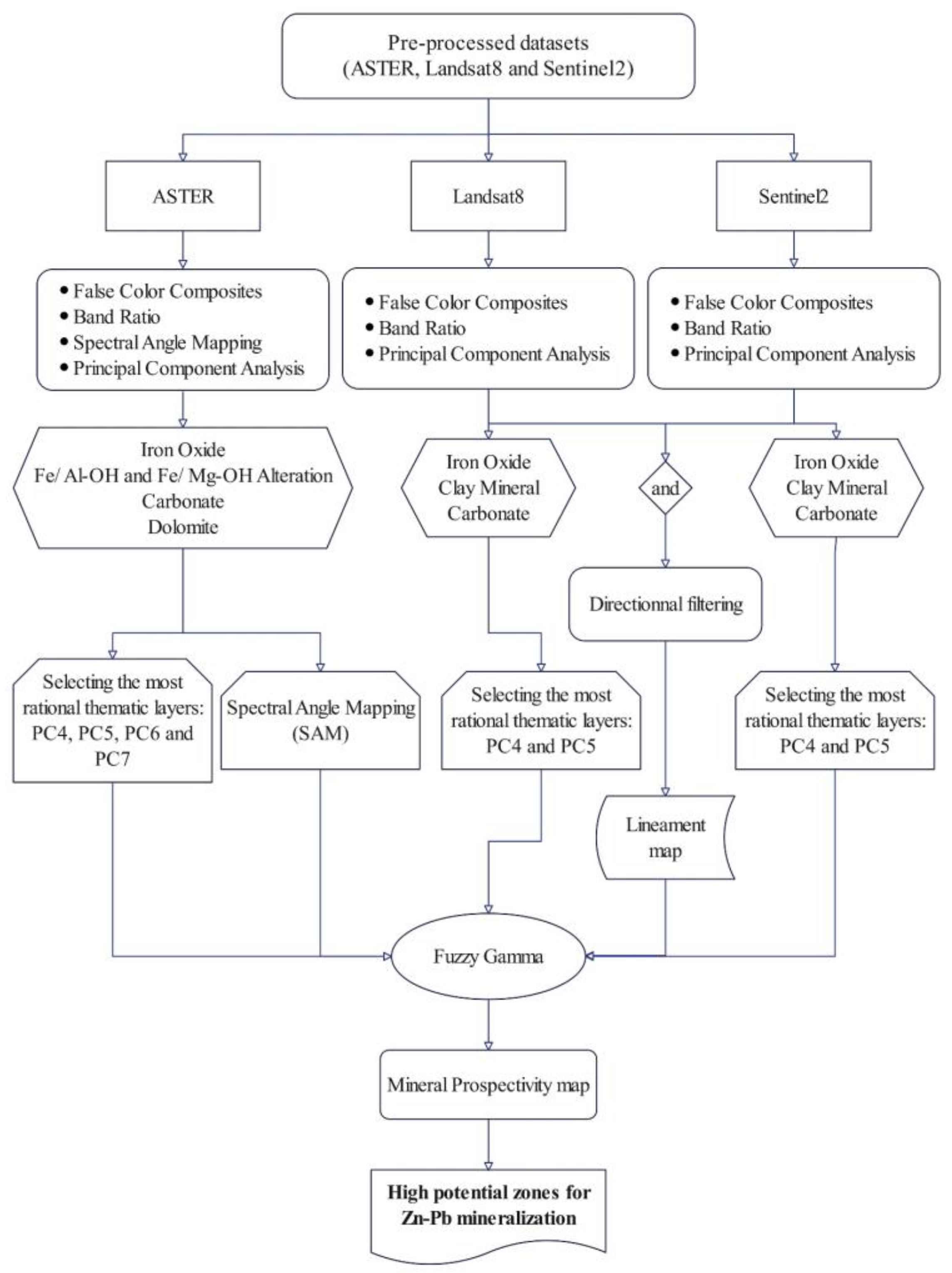
An overview of the methodological flowchart is illustrated in Figure 2. Image-processing methods, namely false color composites (FCCs), band ratio (BR), principal component analysis (PCA), and spectral angle mapping (SAM) were performed to extract spectral information from atmospheric-corrected remote-sensing datasets. Directional filtering was implemented to the Landsat-8 data for extracting lineament features. Subsequently, to generate a mineral prospectivity map of the study area, the most logical layers related to alteration zones and structural features were integrated using fuzzy logic modeling. The accuracy of the results was verified by comparing the locations of the documented Pb-Zn mineralization in the study area.
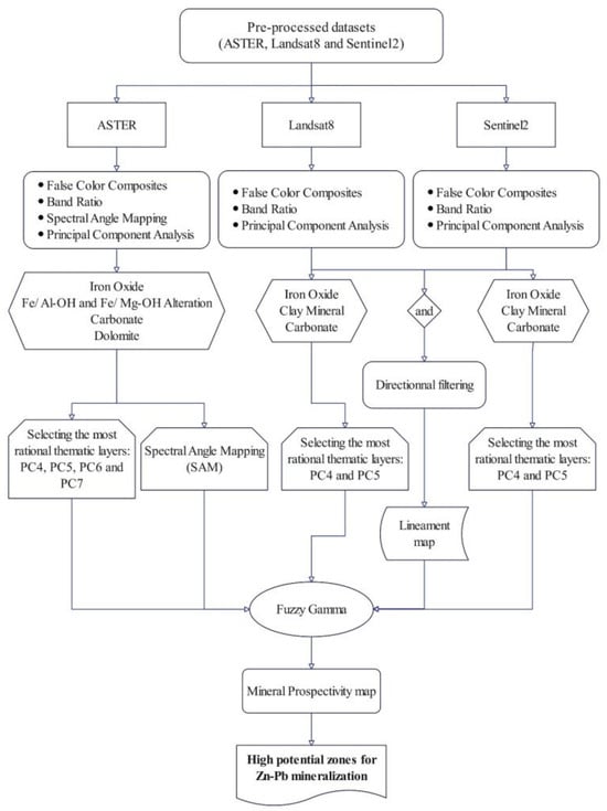
Figure 2.
An overview of the methodological flowchart used in this study.
3.2.1. False Color Composites (FCCs)
Digital images are usually displayed in 3 main colors, red, green, and blue (RGB) [53]. Each of these bands represents different parts of electromagnetic energy and each one is black and white color alone, and a color image is created from the combination of the three bands. The three colors red, green, and blue are used in multispectral images to show the spectrum of the mineral index in the form of a color combination, which shows the highest reflection in the spectrum of that mineral [54,55]. By knowing how the desired phenomenon behaves in different wavelength bands, one can choose the appropriate bands for combination and finally interpret the resulting colors. To create an overview of the lithological units in the study area, the red–green–blue (RGB) false color combination of 2, 5, and 7 for Landsat-8 and 2, 8, and 12 bands for Sentinel-2 was developed, respectively. The RGB images were selected to map lithological units based on spectral characteristics related to iron oxides Fe3+ and Fe3+/Fe2+ and clay and carbonate minerals.
3.2.2. Band Ratio (BR)
Ratio images are obtained by dividing the values of the image elements in one spectral band by the values of the image elements corresponding to the other band for each pixel. By comparing the elements in the two images, a new digital image is generated. The main advantage of the created image is that it conveys the image characteristics regardless of the exposure conditions caused by topographical changes [56]. The band ratio images are acknowledged to enhance spectral contrasts between the bands measured in the ratio operation and have efficaciously been used in identifying hydrothermal alteration zones [57,58,59]. By rationing bands with certain absorption and reflectance, the pixels corresponding to particular minerals are highlighted [60].
VNIR spectral bands (0.45 to 1.2 µm) contain the most important information for the identification of iron oxide/hydroxide (Fe3+/Fe2+) [61]. In this study, the 4/2 band ratio of Landsat-8, Sentinel-2, and ASTER data was used to characterize iron oxide/hydroxide. Alteration minerals, containing hydroxyl (Al-OH) and carbonates, contain absorption characteristics in the 2.1–2.5, while the spectral reflectance usually occurs in the 1.55–1.75 µm. These features are compatible with band 7 (2.11–2.29 µm) and band 6 (1.57–1.65 µm) of Landsat-8, as well as band 12 (2.100–2.280 µm) and band 11 (1.565–1.655 µm) of Sentinel-2, respectively [14,62]. Consequently, in this research, the 11/12 band ratio of Sentinel-2 and the 6/7 band ratio of Landsat-8 were utilized to identify hydroxyl-bearing alteration minerals and carbonate minerals.
Several mathematical expressions are used to identify mineral groups that are called relative absorption band depth (RBD). In this method, the numerator is the sum of the bands indicating the shoulders for a particular absorption and the denominator is the band that has the minimum absorption feature [33]. The Al-OH absorption features at 2.17 to 2.20 µm are matched with the bands 5 and 6 of ASTER, although Mg-Fe-OH and CO3 absorption features are positioned in 2.30 to 2.35 µm corresponding with the bands 7 and 8 of ASTER [14,39,63,64]. Carbonate minerals contain diagnostic CO3 spectral absorptions of about 2.35 μm, which can be suggestively used to map carbonate-bearing rocks [65,66]. The carbonate minerals (e.g., calcite and dolomite) display typical narrow absorption features about 2.35 μm analogous to the band 8 (2.295–2.365 μm) of ASTER [67]. Furthermore, dolomite absorption features are normally focused at 2.20 to 2.30 µm, which are coincident with the bands 6 and 7 of ASTER [57]. Thus, calcite and dolomite minerals can be differentiated by different absorption features between 2.33 and 2.45 μm [67,68]. Accordingly, (i) to map Al/Fe-OH minerals the RBD of (5 + 7)/6, (ii) to identify Mg-Fe-OH/CO3 minerals the RBD of (7 + 9)/8, and (iii) for detecting dolomite the RBD of (6 + 8)/7 were applied in this study.
3.2.3. Principal Component Analysis (PCA)
In satellite images, there is usually a correlation between multispectral bands, especially adjacent bands. The PCA method is related to multivariate analysis, which can be used to transfer a series of multispectral images in such a way that the new components are not correlated with each other and are arranged in a way that can describe the differences in the images [69]. These components show the inherent differences of the main bands in a statistical and compact way. The principal components can be used to condense the information available in a number of bands, for example, the seven bands of Landsat are converted into two or three bands. With this work, we will have maps with complete and summary information, and the analysis of these new images will be more accurate than the analysis of raw images. Usually, the first image obtained by this method contains 80 percent of the information and is the most accurate image, the subsequent images have less information. Considering the variance of the information in the components and the uniqueness of the information in each component, this method can be used to recognize changes [69].
The PCA process uses the principal component transformation method to diminish correlated multispectral data [70,71]. This method is usually applied to a square symmetric matrix. It is based on the covariance matrix or correlation matrix [71]. Selective PCA could be utilized to decrease the dimensionality of a dataset while diminishing the loss of data in addition to improving and identifying the spectral contrast between two different spectral regions [72]. The PCA is used to detect hydrothermal alteration zones and lithological units using the various spectral bands of remote-sensing datasets [30,73].
The eigenvector loadings have characteristic information akin to the spectral features of alteration minerals that could be predictable from the definite spectral bands in the VNIR and SWIR regions [70]. Accordingly, a PC comprises the reflective and absorptive bands of a mineral group with reverse marks that improve that mineral group as bright or dark pixels in the PC image. A positive mark in a reflective band reveals the alteration mineral as bright pixels, whereas a negative mark in a reflective band depicts the alteration mineral as dark pixels [70]. In this analysis, the PCA method was applied based on the covariance matrix for the selected bands of Landsat-8 (bands 1–7), Sentinel-2 (bands 2, 3, 4, 8, 11, and 12), and ASTER (VNIR + SWIR bands) to identify alteration mineral assemblages. Table 2, Table 3 and Table 4 show the eigenvector matrix for the selected bands of the datasets.

Table 2.
Eigenvector matrix of principal component analysis for selected Landsat-8 bands (bands 1 to 7) used in this study.

Table 3.
Eigenvector matrix of principal component analysis for selected Sentinel-2 bands (bands 2, 3, 4, 8, 11, and 12) used in this study.

Table 4.
Eigenvector matrix of principal component analysis for selected ASTER bands (VNIR + SWIR) used in this study.
3.2.4. Spectral Angle Mapping
Spectral angle mapping (SAM) is a supervised spectral classification method [74,75]. In this method, the similarity between the reference spectrum and the pixel spectrum is determined by computing the angle between the spectra in such a way that they are considered vectors in a multi-dimensional space [76]. This method is insensitive to the spectra when run on calibrated reflectance data. Bright pixels show the least distortion and pixels with a lower degree of brightness show the highest distortion with the reference spectrum [74]. To identify the altered areas, some of the alteration minerals in these areas were highlighted by the SAM applied to the ASTER VNIR + SWIR bands. In this analysis, the reference spectra of hematite, kaolinite, calcite, and dolomite were extracted from the USGS spectral library. A number of rule images and a classified image are the output of the SAM algorithm. The spectral angle in radians from the reference spectrum for each class is estimated based on the pixel values of the rule images. Good matches to the endmember spectra are attained by lower spectral angles [77].
3.2.5. Lineament Extraction
The use of remote-sensing methods for the detection and extraction of geological lineaments, including faults, fractures, and dykes due to the high speed of work and low costs is very crucial [78]. The main data used for mapping structural lineaments in the study area were Landsat-8. The extraction of lineaments was obtained using PCA and directional filtering. The PC5 image was selected for applying the directional filtering, because it shows the geological features better compared to other PC images. A directional filter is an edge detector that is typically utilized to calculate the first derivatives of an image. The first derivatives are most obvious when a great change arises among adjoining pixel values. Directional filters could be premeditated for any direction within a fixed space [79]. Hence, directional filters can detect roads, waterways, faults, etc. An edge-detection filter is one that improves those linear features in an image that are preoccupied with a specific direction. A 7 × 7 kernel matrix was selected here to boost semi-smooth and smooth/rough features. Four principal directional filters N–S, E–W, NE–SW, and NW–SE with a 7 × 7 kernel size were applied to the PC5 image of Landsat-8 (Table 5). Regarding the geology map of the study area, duplicate lines using overlapping prepared layers such as roads and artificial complications were removed.

Table 5.
Directional filters with 7 × 7 kernel matrix.
3.2.6. Fuzzy Gamma Methods
The fuzzy set theory, presented by [80], affords a mathematical outline for investigating natural singularities. It characterizes an object categorized by the sorted classifications of membership. Membership rates are allocated between 0 and 1, representing the level of inevitability or the grade of affinity of an object to a specific group [81]. Furthermore, it allows for a more elastic illustration of doubt and vagueness in data analysis. A fuzzy set of A is a set of methodical pairs:
where µ_A (x) is named the membership function or membership grade of x in A. µ_A (x) maps x to the membership space (M), once M contains only the two points 0 and 1. The range of µ_A (x) is [0, 1], where zero expresses non-membership and one expresses full membership [80].
Fuzzy logic modeling was efficaciously used for mineral potential mapping [14,82,83,84]. A set of fuzzy membership rates is articulated in a constant sequence from 0 to 1. Function–member rates are known for each evidence layer that will be combined. A whole of sheet maps (fuzzy membership) constructed on the consequence distance of features are weighted (between 0 and 1) [84]. A fuzzy gamma operator was applied to combine multiple indicator maps with fuzzy membership functions to generate a mineral potential map in this analysis. The membership weights were assigned using expert knowledge of the study area. The gamma value, controlling the degree of influence of each membership function, was estimated through a trial-and-error approach [84]. Therefore, in this analysis, the gamma value of 0.8 was selected. Note that the selection of fuzzy membership weights and the gamma value necessitates expert knowledge and could be personalized to a particular study area and the purposes of the study. Table 6 shows the fuzzification parameters for the input layers used in this analysis.

Table 6.
Fuzzification parameters for the input layers used in this analysis.
4. Results and Discussion
4.1. Lithological and Alteration Mineral Mapping
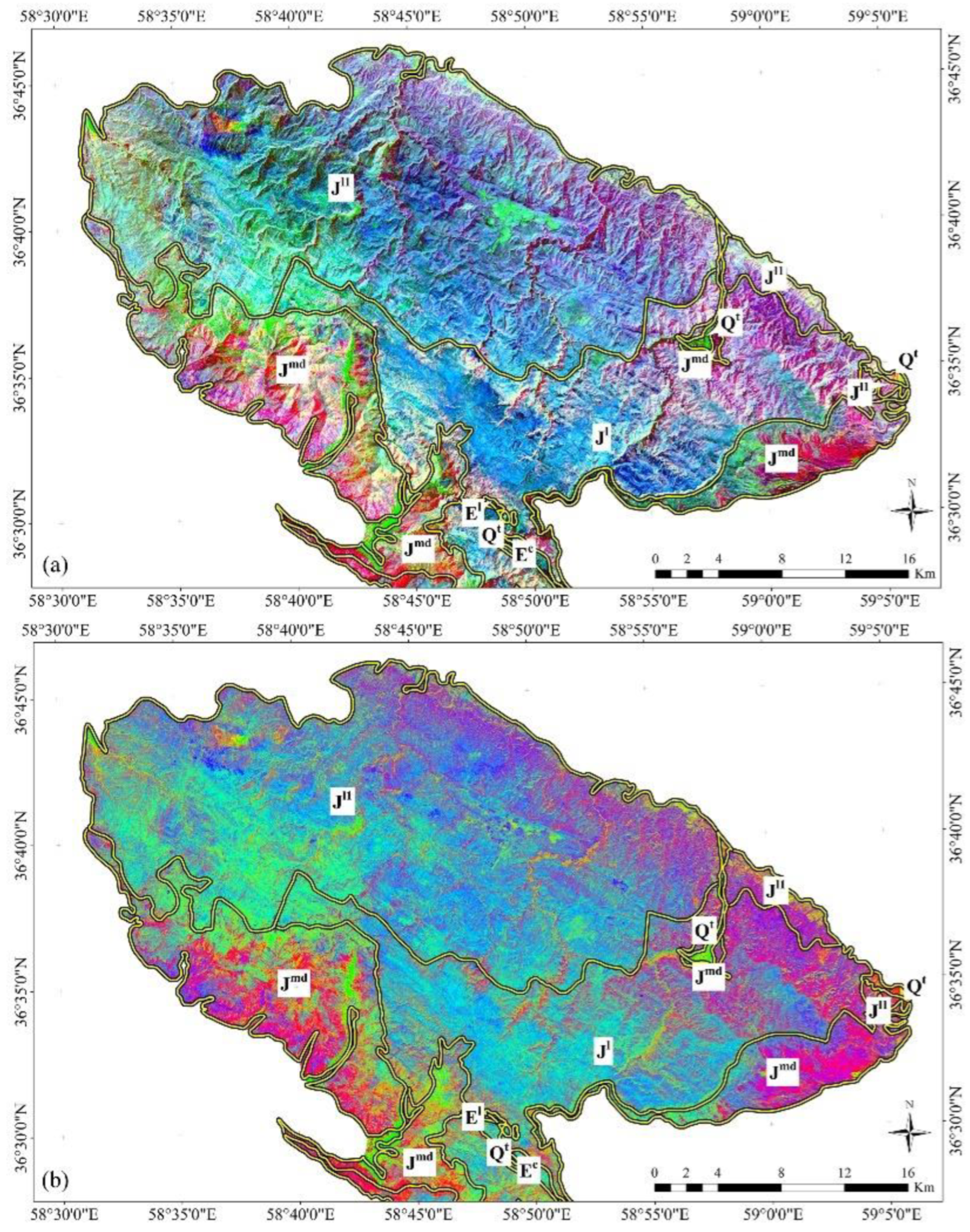
To overview the lithological units in the study area, the red–green–blue (RGB) false color combination of the bands 2, 5, and 7 and 2, 8, and 12 were developed for Landsat-8 and Sentinel-2, respectively (Figure 3a,b). The RGB images could discriminate some of the lithological units with spectral characteristics related to iron oxides Fe3+ and Fe3+/Fe2+ and clay and carbonate minerals. The lithological units of the study area are mainly composed of the thick carbonate rocks of the middle and upper Jurassic ages. The main units of this region are thick-layered limestones with interlayers of light gray to green shales (equivalent to Lar formation) (J1) and medium to thick limestone, light to dark gray, that is partially dolomitic (equivalent to Lar formation) (J1l) that appeared purple in the satellite image maps (Figure 3a,b) due to the presence of Al, Fe, and OH compounds that are slightly mixed with Mg and Fe ions. The western part of unit J1, due to the presence of iron oxides Fe+2 in carbonates, has appeared in green and turquoise colors. Very thin gray micritic limestone with interlayers of gray to green shale (equivalent to Delichai formation) (Jmd) can be seen as magenta and with some green interlayers in the image maps, probably due to having Fe+3 and Fe+2 irons in the carbonates (Figure 3a,b). According to the geological map of the study area (see Figure 1), the differentiation of the lithological units in the image maps obtained from Landsat-8 and Sentinel-2 were almost similar. However, iron oxide/hydroxides were better mapped and discriminated in the carbonate background of the study area using Sentinel-2 RGB image map (Figure 3b).
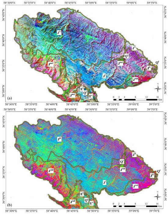
Figure 3.
(a) RGB color composite of bands 2, 5, and 7 for Landsat-8. (b) RGB color composite of bands 2, 8, and 12 for Sentinel-2.
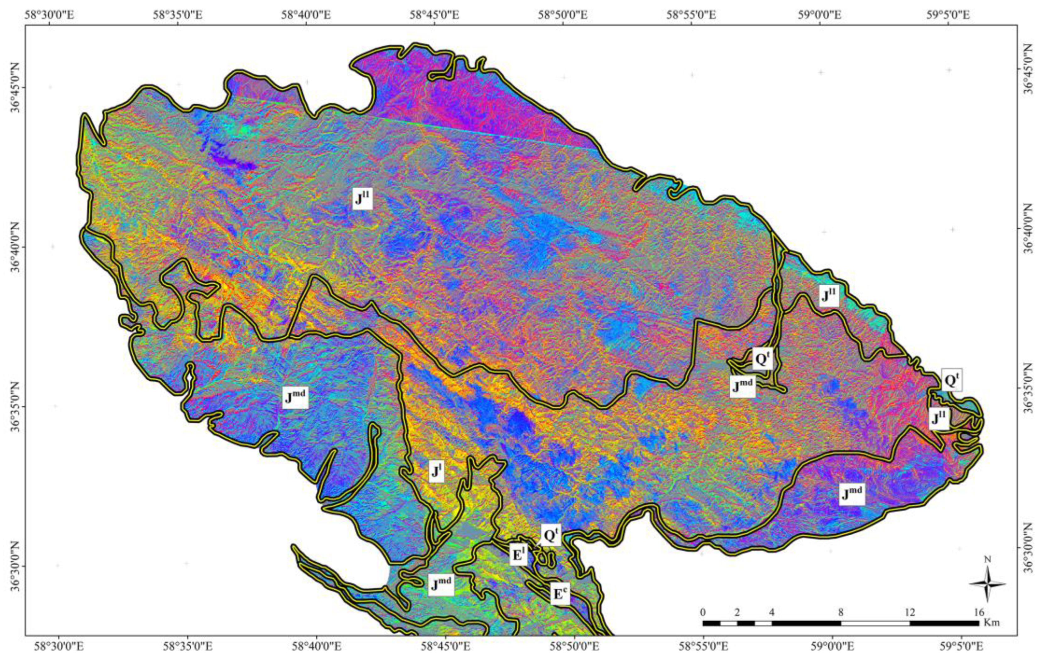
An RGB false color composite of ASTER using the bands 6, 2, and 8 was developed to distinguish the lithological units containing Al/Fe-OH, Fe+2/Fe3+, and Mg/Fe/OH-CO3 absorption properties (Figure 4). The thin-layer limestone unit with shale interlayer (Jmd) and parts of the Jl1 unit, due to the presence of Al/Fe-OH minerals mixed with Mg-Fe, OH, and CO3 ions, appear purple. The western part of the Jl1 unit and a limited part of the Jl unit in the image, due to the combination of Mg/Fe/OH-CO3, Al/Fe-OH minerals with Fe2+/Fe3+ ions, appear in yellow color. The Ec unit is seen in dark purple due to the presence of Al/Fe-OH and Mg/Fe/OH-CO3 minerals. The southern parts of the Jmd units appear green due to the presence of Fe+2/Fe3+ ions.
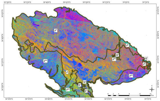
Figure 4.
RGB color composite of bands 6, 2, and 8 for ASTER.
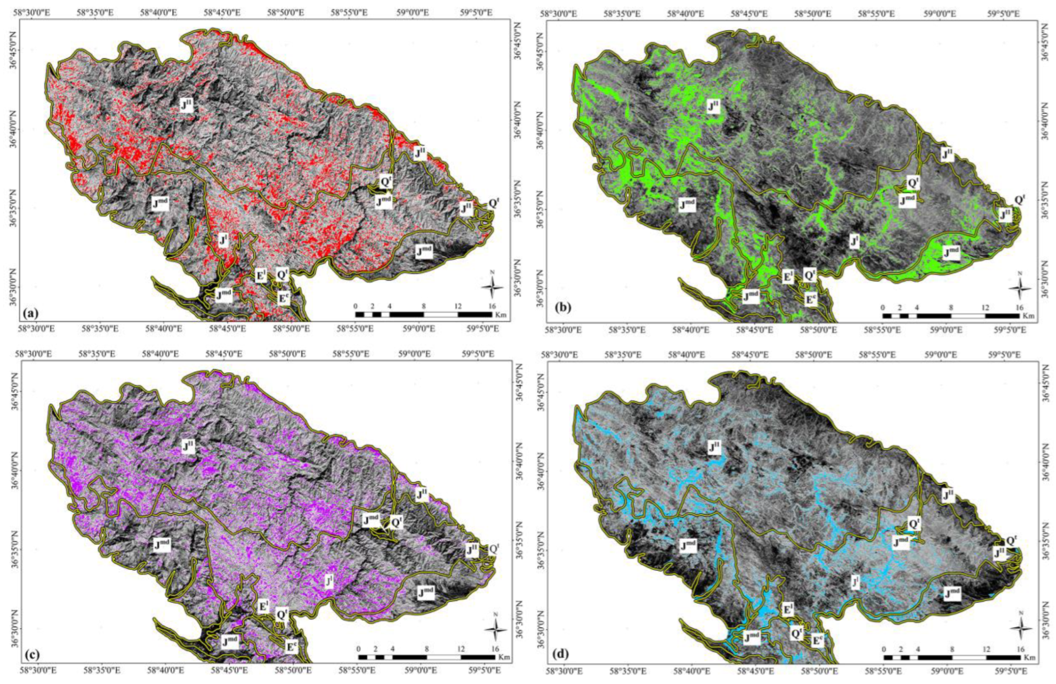
Figure 5 shows the results of the band ratio method in order to highlight iron oxides and hydroxides, and clay minerals and carbonates derived from the Landsat-8 and Sentinel-2 spectral bands. The band ratio 4/2 of Landsat-8 and Sentinel-2 show the spatial distribution of iron oxide and hydroxide minerals (as red and green pixels, respectively) that are mostly located in the J1 and Jl1 units and some in the Jmd units (Figure 5a,b). The Landsat-8 band ratio 6/7 and Sentinel-2 band ratio 11/12 show the surface distribution of alteration minerals containing hydroxyl and carbonates (as magenta and turquoise pixels, respectively) (Figure 5c,d). Band ratio images used for the Landsat-8 data show a higher abundance of clay and carbonate minerals than the Sentinel-2 band ratio images (Figure 5c,d). This is because the band 12 (2.100–2.280 µm) of Sentinel 2 covers the absorption characteristics of minerals containing hydroxyl, while carbonates have absorption characteristics in the wavelength of 2.350 to 2.450 µm. Therefore, carbonates cannot be identified appropriately using the 11/12 band ratio of Sentinel-2.
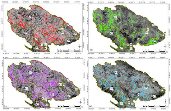
Figure 5.
Band ratio image maps showing the spatial distribution of the iron oxide/hydroxides and clay and carbonate minerals. (a) The 4/2 band ratio image map of Landsat-8 showing the iron oxide/hydroxide minerals as red pixels; (b) the 4/2 band ratio image map of Sentinel-2 showing the iron oxide/hydroxide minerals as green pixels; (c) the 6/7 band ratio image map of Landsat-8 showing the clay minerals and carbonates as magenta pixels; (d) the 11/12 band ratio image map of Sentinel-2 showing the hydroxyl-bearing minerals as turquoise pixels.
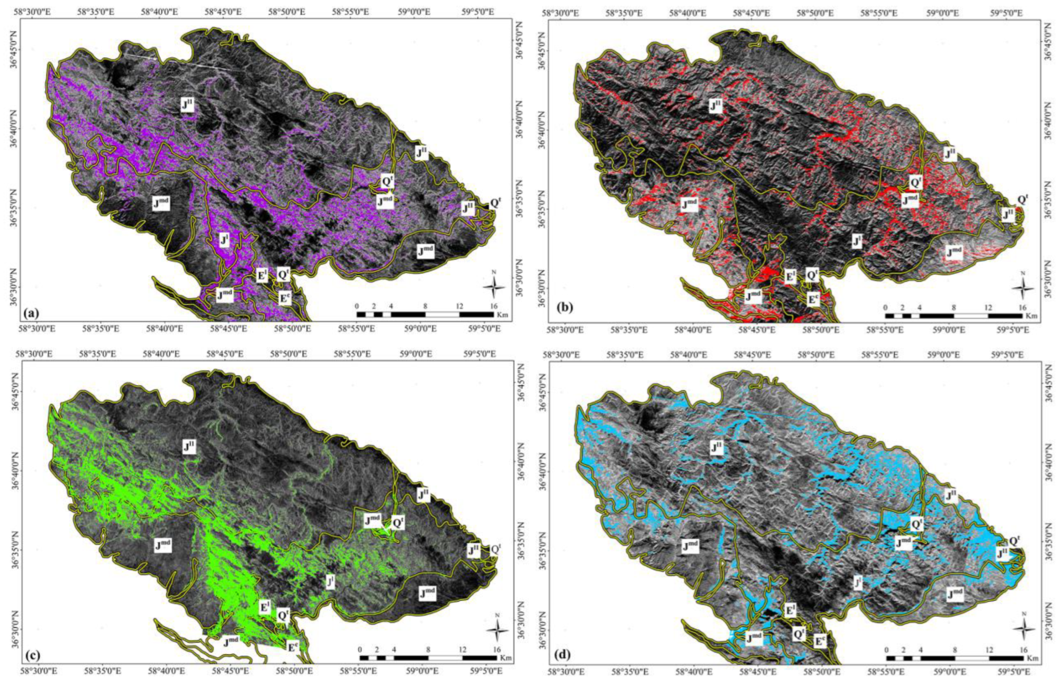
The band ratio 4/2 of ASTER shows that iron oxide and hydroxide minerals are mapped in the J1 and J11 units (magenta pixels in Figure 6a). However, the surface abundance of iron oxide and hydroxides is also mapped in some parts of the Jmd units (Figure 6a). Using the ASTER RBD of (5 + 7)/6, Al/Fe-OH minerals are highlighted as red pixels (Figure 6b). Comparing the results with the geological map of the studied area shows that the high abundance of the Al/Fe-OH minerals is related to the Jmd lithological unit (Figure 6b). The northwestern part of the J11 units and the central part of the J1 units also showed the spatial distribution of the Al/Fe-OH minerals (Figure 6b). Figure 6c shows the RBD of (7 + 9)/8 for mapping the surface abundance of the Mg/Fe/OH-CO3 minerals (green pixels). These minerals are mapped in the E1, Ec, Jl, Jl1, and Jmd geological units. The dolomite units are also exposed in the form of turquoise pixels in the Jl, Jl1, and Jmd units using the RBD of (6 + 8)/7 (Figure 6d). The surface distribution of dolomite units is less compared to Mg/Fe/OH-CO3 minerals. However, sub-pixel mapping techniques will help for the better differentiation of the dolomite units and Mg/Fe/OH-CO3 minerals.
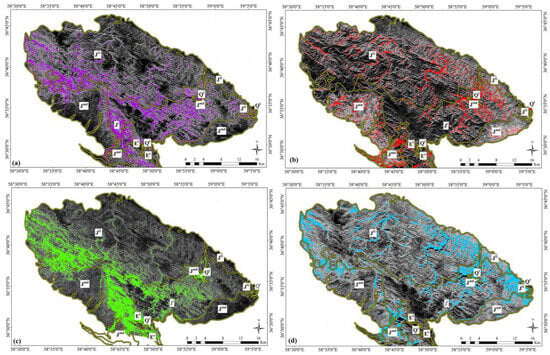
Figure 6.
ASTER band ratio image maps showing the spatial distribution of the iron oxide/hydroxides Al/Fe-OH and Mg-Fe-OH/CO3 minerals and dolomite. (a) The 4/2 band ratio image map showing the iron oxide/hydroxide minerals as magenta pixels; (b) the RBD of (5 + 7)/6 image map showing the Al/Fe-OH minerals as red pixels; (c) the RBD of (7 + 9)/8 image map showing the Mg-Fe-OH/CO3 minerals as green pixels; (d) the RBD of (6 + 8)/7 image map showing dolomite as turquoise pixels.
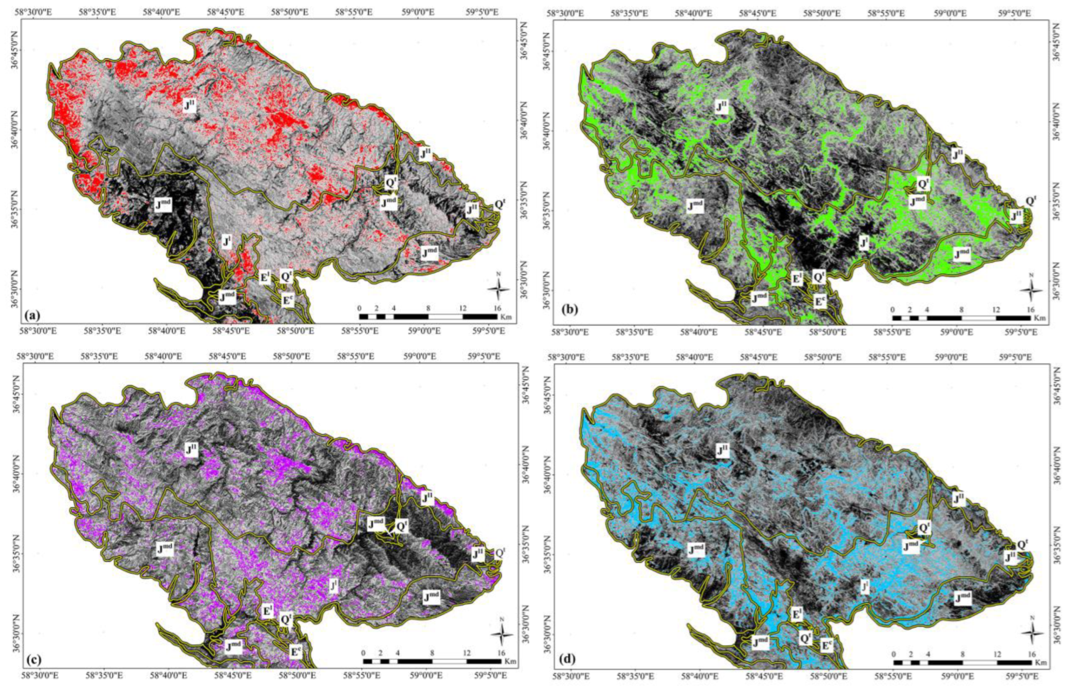
The analysis of eigenvector loadings obtained by the PCA method for Landsat-8 and Sentinel-2 shows that PC4 and PC5 contain key information related to minerals containing hydroxyl and carbonate and iron oxide/hydroxide. Table 2 shows the eigenvector matrix for the selected Landsat-8 bands. Iron oxide/hydroxide minerals are characterized by high absorption characteristics at about 0.40 to 1.10 μm and high reflectivity at about 1.60 μm [65]. The PC4 of Landsat-8 data has strong positive loadings in bands 1 (0.47) and 2 (0.25) and great negative loading in band 4 (−0.80). Therefore, according to the spectral characteristics of iron oxide in the PC4 image, iron oxide/hydroxides appeared as dark areas. In order to show the iron oxide as bright pixels, the PC4 image was inverted. The spatial distribution of iron oxide/hydroxides (red pixels) is mainly identified in the Jl, Jl1, and Jmd units (Figure 7a).
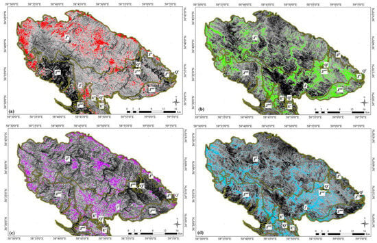
Figure 7.
PC image maps showing the spatial distribution of the iron oxide/hydroxide minerals and clay minerals and carbonates. (a) The PC4 image map of Landsat-8 showing the iron oxide/hydroxide minerals as red pixels; (b) the PC5 image map of Landsat-8 showing the OH-bearing minerals as green pixels; (c) the PC4 image map of Sentinel-2 showing the iron oxide/hydroxide minerals as magenta pixels; (d) the PC5 image map of Sentinel-2 showing the OH-bearing minerals as turquoise pixels.
Examining PC5 shows that band 6 (0.68) has a positive and strong loading and band 7 (−0.66) has a great and negative loading. The band 6 of Landsat-8 covers the spectral region (1.6 μm) where all OH-bearing minerals have maximum reflectance, while Al (OH)-bearing minerals show major absorption in band 7. Therefore, OH-minerals are represented as bright pixels in the PC5 image. Figure 7b shows the spatial distribution of OH-minerals as green pixels in the study area. In the central part of the Jl1 units and Jmd units in the southwestern of the study area, a high abundance of OH-minerals can be seen in the PC5 image (Figure 7b). A comparison of the PCA results and Landsat-8 band ratio shows that the spatial distribution of the iron oxide/hydroxide minerals and hydroxyl-bearing minerals is generally lower in PC images.
According to the eigenvector loading for Sentinel 2, PC4 has strong positive loading in band 2 (−0.53) and great negative loading in band 4 (0.51) (Table 3). Thus, bright pixels (magenta pixels in the image map) indicate areas prone to the mineralization of iron oxide/hydroxide compounds. The results show the distribution of iron oxide/hydroxides in the Jl, J11 and Jmd units (Figure 7c). Hydroxyl minerals can be mapped as dark pixels in the PC5 image due to great negative loading in band 11 (0.68) and strong positive loading in band 12 (0.63). Figure 7d shows an inverted PC5 image that highlights hydroxyl as bright pixels (turquoise pixels in the image map), which are associated with the Jl, J11, and Jmd units. The spatial distribution of iron oxide and hydroxyl iron mineralization in Sentinel-2 PC images is less revealed compared to Landsat 8 PC images (see Figure 7a–d).
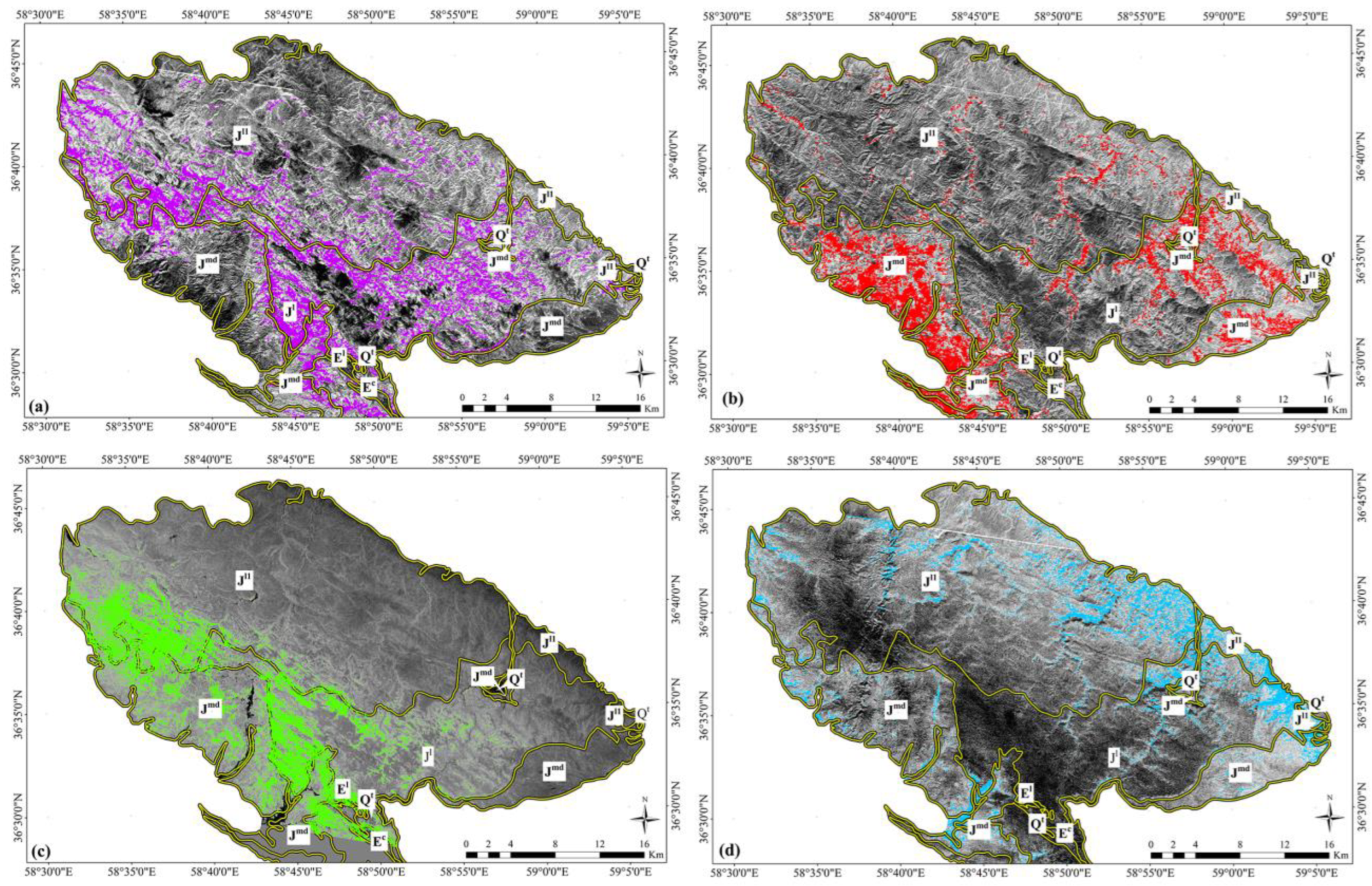
The PCA technique was also applied to the VNIR + SWIR bands of ASTER data to highlight alteration minerals. According to the spectral responses of alteration minerals in VNIR and SWIR bands of ASTER [63], the PC4 image contains spectral properties related to Mg-Fe-OH/CO3 minerals because of the positive loading of band 4 (0.46) and negative loadings of bands 7 (−0.46) and 8 (−0.65) (Table 4). Hence, the mineral groups such as chlorite, epidote, calcite, and dolomite are represented as bright pixels (magenta pixels in the image map) in the PC4 image (Figure 8a). Some areas of high abundance of Mg-Fe-OH/CO3 minerals located in the Jl and Jmd units are recognizable. The PC5 has strong positive loadings in band 4 (0.29), while it shows strong negative loading in band 2 (−0.64) (Table 4). According to the spectral position of the ASTER bands 2 (0.63–0.69 μm) and 4 (1.60–1.70 μm), iron oxide/hydroxide minerals are mapped as bright pixels (red pixels in the image map) in the PC5 image (Figure 8b). Some areas of the spatial distribution of iron oxide/hydroxide minerals located in the Jl and Jmd units are recognizable.
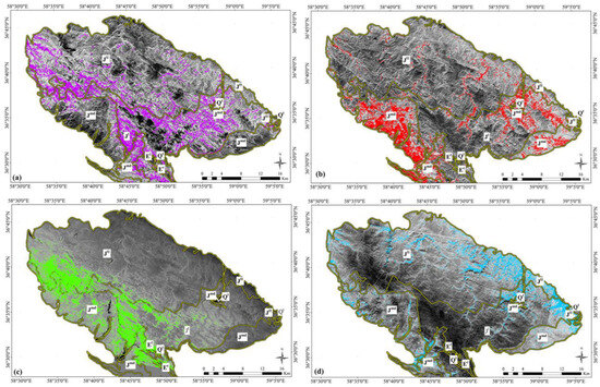
Figure 8.
The PC image maps derived from VNIR + SWIR ASTER. (a) The PC4 image map showing the Mg-Fe-OH/CO3 minerals as magenta pixels; (b) the PC5 image map showing the iron oxide/hydroxide minerals as red pixels; (c) the PC6 image map showing the Al-OH-bearing minerals as green pixels; (d) the PC7 image map showing the carbonate units as turquoise pixels.
The PC6 shows a strong positive contribution in band 4 (0.52) and negative great loadings in bands 5 (−0.33) and band 6 (−0.58) (Table 4). Therefore, the minerals containing Al-OH such as kaolinite, muscovite, and illite can detected as bright pixels in the PC6 image. The spatial distribution of Al-OH-bearing minerals is clearly visible in the units Jmd and Jl (green pixels) (Figure 8c). The PC7 contains a strong positive loading in band 4 (0.40) and a great negative contribution in band 9 (−0.83) (Table 4). The band 9 (2.360–2.430 µm) of ASTER contains CO3 spectral absorptions to identify carbonate-bearing rocks [65]. Accordingly, the PC7 image can be used to map carbonate-bearing rocks as turquoise pixels in the study area (Figure 8d). Most of the carbonate units such as Jmd, J11, E1, and Jl are mapped in the PC7.
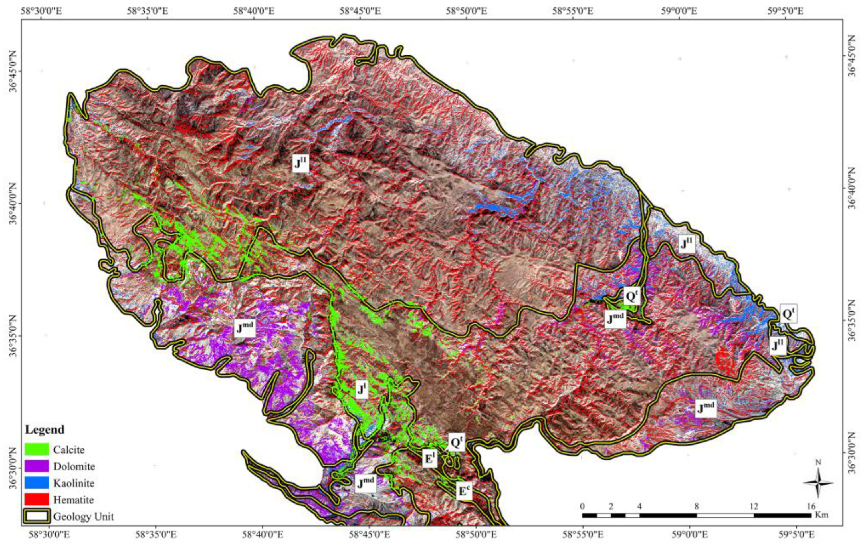
The SAM classification method was applied to the ASTER VNIR + SWIR bands for the detailed mapping of the spatial distribution of alteration minerals such as iron oxide/hydroxide group (hematite,), Al-OH minerals (kaolinite), and carbonate (calcite and dolomite). The outputs of the SAM are rule images for end members. The pixels that have a smaller spectral angle are seen as darker in the rule images and show the highest overlap with the reference spectrum. Figure 9 shows the SAM classification for the study area. The surface distribution of hematite was mapped in the Jmd, J1, Ec, E1, and J11 lithological units. kaolinite was mostly mapped in the Qt, J1, and J11 lithological units. The spatial distribution of calcite and dolomite shows that the J11 and J1 lithological units have a high abundance of calcite, while dolomite is typically mapped in the Jmd lithological unit.
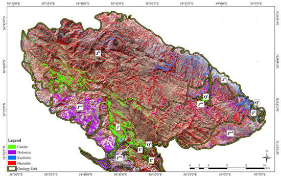
Figure 9.
The SAM classification map of alteration minerals in the study area.
In the rock samples collected from the lithological units in the study area, the presence of quartz, dolomite, calcite, muscovite, chlorite, hematite, limonite, illite, jarosite, pyrite, galena, and sphalerite were recorded by an XRD analysis (Table 7). It shows that the mineralogical information derived from the remote-sensing analysis was reliable and accurate.

Table 7.
Minerals detected in the collected rock using an XRD analysis.
4.2. Structural Mapping
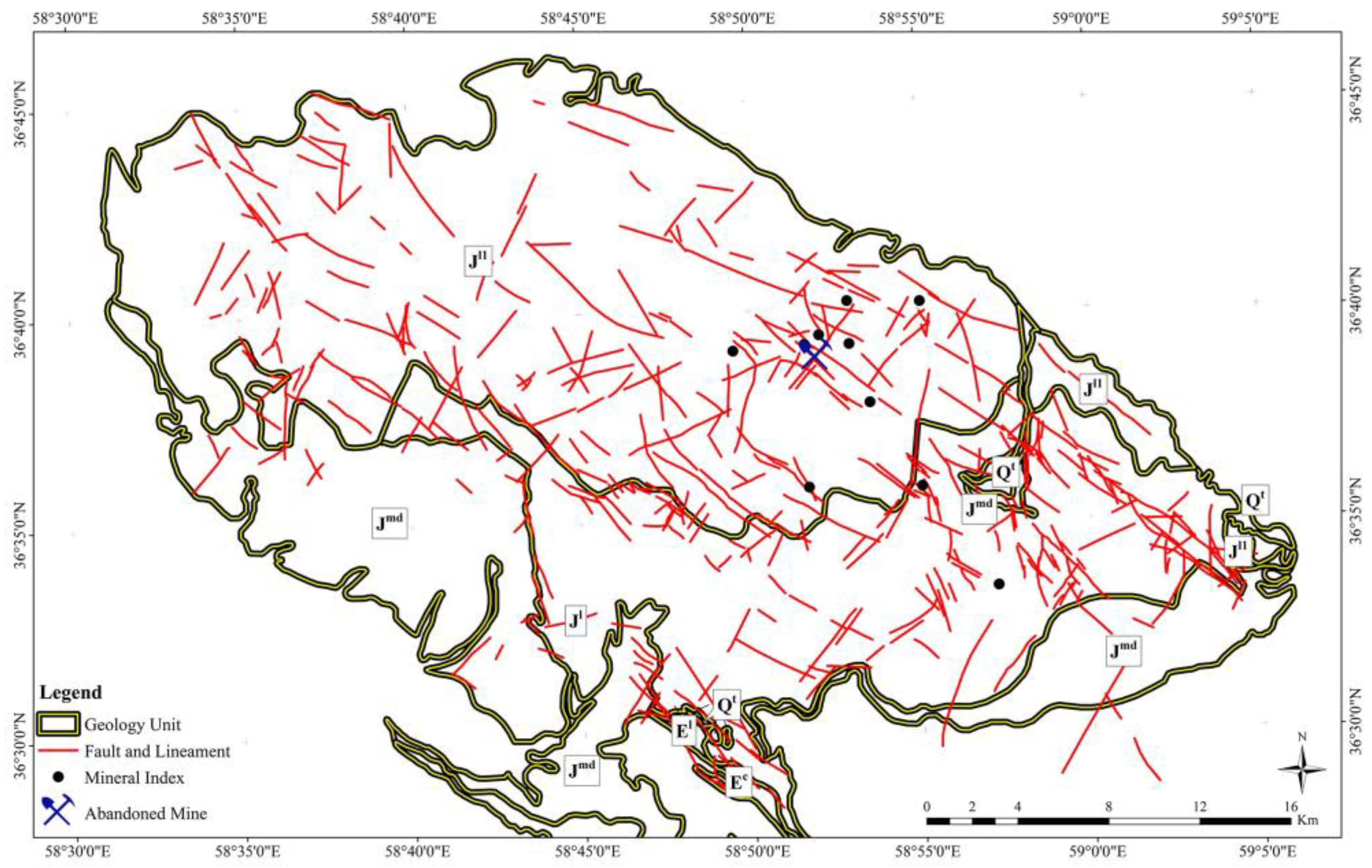
Figure 10 shows the lineament map extracted from the PC5 image of Landsat-8 for the study area. NW–SE and NE–SW trends are the dominant directions for structural features in this region. Most of the long lineaments trend NE–SW and NW–SE and some short lineaments strike E–W. NE-SW-striking lineaments are often cut by shorter NW–SE-trending lineaments, especially in the northern and northeastern parts of the study area. NE–SW- and NW–SE-trending lineament systems are extensive in the eastern part and less in the southwestern sectors. Most of the known Pb-Zn indices and abandoned mines are located along the intersection of NE–SW and NW–SE lineaments in the study area. It is documented that structural features typically control carbonate-hosted Pb-Zn mineralization locations. Pb-Zn-bearing fluids are normally concentrated in the fault zones during regional compression and precipitated during hydraulic fracturing of carbonate host rocks [82].
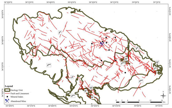
Figure 10.
Lineament map of the study area extracted from the PC5 image of Landsat-8.
4.3. Generating Prospectivity Map
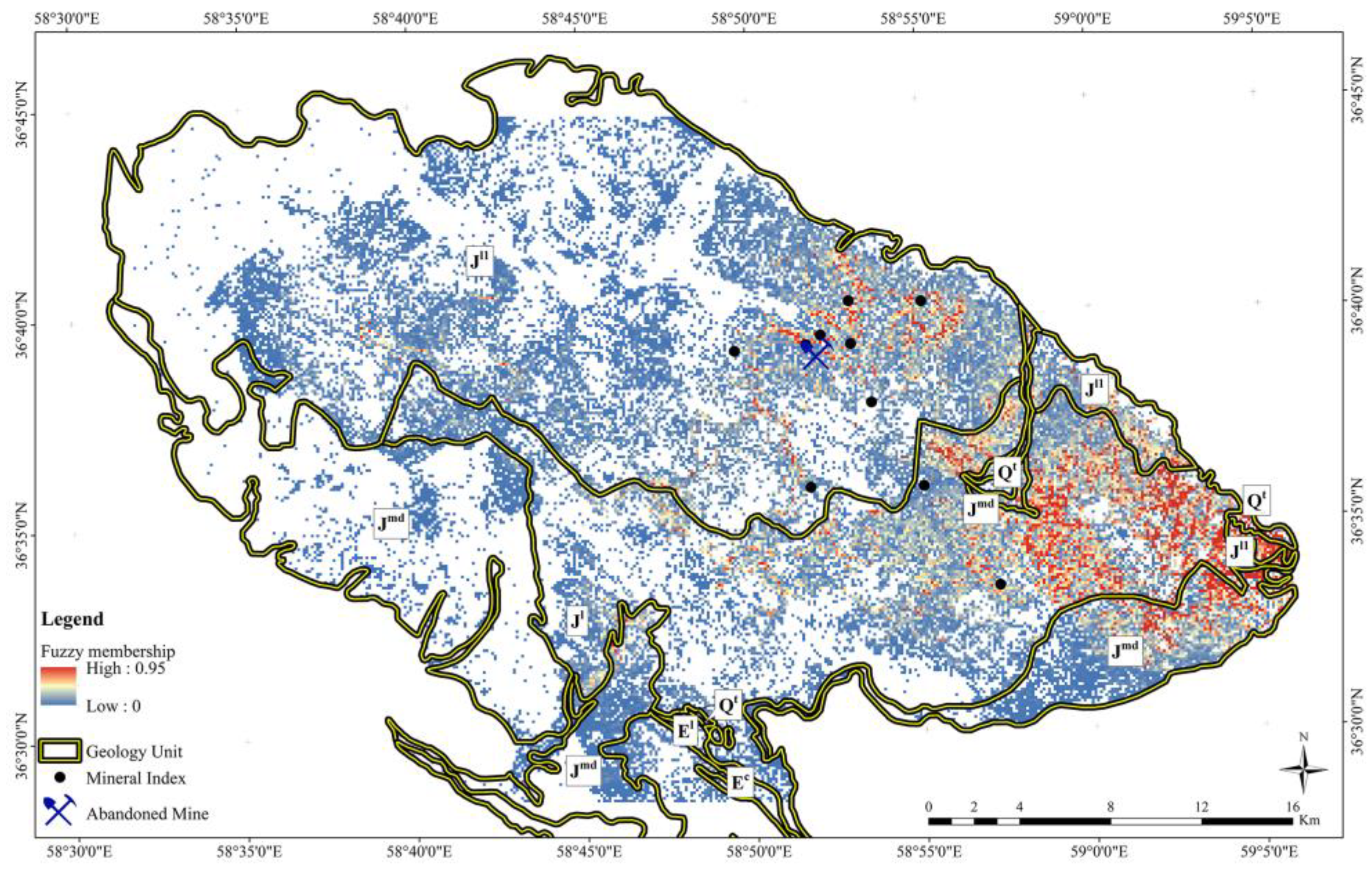
The fuzzy logic model was used to produce the mineral prospectivity maps of potential zones for Pb-Zn mineralization in the study area using the most informative thematic layers derived from image-processing techniques. In this analysis, PCA, SAM, and lineament outputs were considered and weighted as the most informative thematic layers. Therefore, (i) the PC4 and PC5 derived from Landsat-8 and Sentinel-2; (ii) PC4, PC5, PC6, and PC7 derived from ASTER (iii) hematite, kaolinite, calcite, and dolomite rule images derived from SAM (ASTER); and (iv) lineament extracted from the PC5 image of Landsat-8 were considered and integrated with fuzzy gamma operator (0.80 and 0.95) for generating the mineral prospectivity map of the study area (see Table 6). Figure 11 shows the mineral prospectivity map of the study area. Fuzzy membership evaluation shows that a high favorability index is associated with some lithological units and sectors in the study area. The J1 and Jl1 units show a high value of 0.7 to 1.0, especially in the northern and northeastern parts. Most of the Pb-Zn mineral indices and abandoned mines are located in high-value zones (Figure 11). Some high-value zones can also be found in the central parts and associated with the Jmd lithological units (Figure 11). The presence of mineral indications and mines in the high-value zones validated the applicability of the Pb-Zn mineral prospective map for detailed mineral exploration programs in the future.
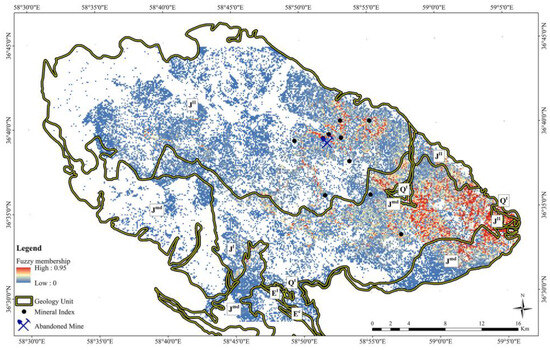
Figure 11.
Mineral prospectivity map of the study area derived from the fuzzy logic model.
5. Conclusions
This investigation demonstrates the applicability of multi-sensor remote-sensing imagery for Pb-Zn mineralization prospectivity mapping in a sedimentary background. Landsat-8, Sentinel-2, and ASTER satellite data in the range of VNIR and SWIR bands were used for lithological–alteration–structural mapping to generate the Pb-Zn prospectivity map for the Akhlamad area, Razavi Khorasan, NE Iran. The results showed significant information related to alteration minerals (gossan and dolomitization) and the intersection of lineaments that can be obtained by processing the multi-sensor remote-sensing data. Integrating thematic layers by fuzzy logic model helped to generate the Pb-Zn prospectivity map, which appropriately matched with mineral indices and abandoned mines. The potential zones are mostly located in the J11, Jmd, and Jl lithological units. The results of this study recommended several target points for future Pb-Zn exploration in the study area.
Author Contributions
Conceptualization, S.H. and M.G.; methodology, M.S.; software, M.G. and R.A.; validation, S.H., M.S. and A.B.P.; writing—original draft preparation, S.H., M.G. and A.B.P.; writing—review and editing, A.B.P. and M.B.; supervision, A.B.P. All authors have read and agreed to the published version of the manuscript.
Funding
This research received no external funding.
Data Availability Statement
Data are contained within the article.
Acknowledgments
We express our profound gratitude to the Department of Geology, Payame Noor University, Tehran for all the support essential to conducting this research. The Institute of Oceanography and Environment (INOS), Universiti Malaysia Terengganu (UMT) is also acknowledged for providing facilities for editing, rewriting, and re-organizing the manuscript.
Conflicts of Interest
The authors declare no conflicts of interest.
References
- Craw, D.; Upton, P.; Mackenzie, D.J. Hydrothermal Alteration Styles in Ancient and Modern Orogenic Gold Deposits, New Zealand. N. Z. J. Geol. Geophys. 2009, 52, 11–26. [Google Scholar] [CrossRef]
- Clark, D.A. Magnetic Effects of Hydrothermal Alteration in Porphyry Copper and Iron-Oxide Copper–Gold Systems: A Review. Tectonophysics 2014, 624–625, 46–65. [Google Scholar] [CrossRef]
- Mshiu, E.E.; Gläßer, C.; Borg, G. Identification of Hydrothermal Paleofluid Pathways, the Pathfinders in the Exploration of Mineral Deposits: A Case Study from the Sukumaland Greenstone Belt, Lake Victoria Gold Field, Tanzania. Adv. Space Res. 2015, 55, 1117–1133. [Google Scholar] [CrossRef]
- Maleki, M.; Niroomand, S.; Rajabpour, S.; Beiranvand Pour, A.; Ebrahimpour, S. Targeting Local Orogenic Gold Mineralisation Zones Using Data-Driven Evidential Belief Functions: The Godarsorkh Area, Central Iran. All Earth 2022, 34, 259–278. [Google Scholar] [CrossRef]
- Peyghambari, S.; Zhang, Y. Hyperspectral Remote Sensing in Lithological Mapping, Mineral Exploration, and Environmental Geology: An Updated Review. J. Appl. Remote Sens. 2021, 15, 031501. [Google Scholar] [CrossRef]
- Rajan Girija, R.; Mayappan, S. Mapping of Mineral Resources and Lithological Units: A Review of Remote Sensing Techniques. Int. J. Image Data Fusion 2019, 10, 79–106. [Google Scholar] [CrossRef]
- Kakavand, M.; Bonyadi, Z. Evaluation of Alteration Zones around Parmagasu Copper Indication, Kuh Zar, Damghan, Iran, Using ASTER Satellite Data. Geocarto Int. 2022, 37, 16827–16845. [Google Scholar] [CrossRef]
- Adiri, Z.; Lhissou, R.; El Harti, A.; Jellouli, A.; Chakouri, M. Recent Advances in the Use of Public Domain Satellite Imagery for Mineral Exploration: A Review of Landsat-8 and Sentinel-2 Applications. Ore Geol. Rev. 2020, 117, 103332. [Google Scholar] [CrossRef]
- Jain, R.; Sharma, R.U. Airborne Hyperspectral Data for Mineral Mapping in Southeastern Rajasthan, India. Int. J. Appl. Earth Obs. Geoinf. 2019, 81, 137–145. [Google Scholar] [CrossRef]
- Shirmard, H.; Farahbakhsh, E.; Heidari, E.; Pour, A.; Pradhan, B.; Müller, D.; Chandra, R. A Comparative Study of Convolutional Neural Networks and Conventional Machine Learning Models for Lithological Mapping Using Remote Sensing Data. Remote Sens. 2022, 14, 819. [Google Scholar] [CrossRef]
- Ezzati, A.R.M. and K.A. Detection of Hydrothermal Potential Zones Using Remote Sensing Satellite Data in Ramand Region, Qazvin Province, Iran. J. Tethys 2014, 2, 093–100. [Google Scholar]
- Honarmand, M.; Shahriari, H.; Zadeh, M.H.; Ghorbani, A. Enhancing Zn-bearing gossans from GeoEye-1 and Landsat 8 OLI data for non-sulphide Zn deposit exploration. Egypt. J. Remote Sens. Space Sci. 2024, 27, 93–107. [Google Scholar] [CrossRef]
- Ghorbani, A.; Honarmand, M.; Shahriari, H.; Hassani, M.J. Regional scale prospecting for non-sulphide zinc deposits using ASTER data and different spectral processing methods. Int. J. Remote Sens. 2019, 40, 8647–8667. [Google Scholar] [CrossRef]
- Sekandari, M.; Masoumi, I.; Beiranvand Pour, A.; M Muslim, A.; Rahmani, O.; Hashim, M.; Zoheir, B.; Pradhan, B.; Misra, A.; Aminpour, S.M. Application of Landsat-8, Sentinel-2, ASTER and WorldView-3 Spectral Imagery for Exploration of Carbonate-Hosted Pb-Zn Deposits in the Central Iranian Terrane (CIT). Remote Sens. 2020, 12, 1239. [Google Scholar] [CrossRef]
- Traore, M.; Wambo, J.D.T.; Ndepete, C.P.; Tekin, S.; Pour, A.B.; Muslim, A.M. Lithological and Alteration Mineral Mapping for Alluvial Gold Exploration in the South East of Birao Area, Central African Republic Using Landsat-8 Operational Land Imager (OLI) Data. J. Afr. Earth Sci. 2020, 170, 103933. [Google Scholar] [CrossRef]
- Fossi, D.H.; Dadjo Djomo, H.; Takodjou Wambo, J.D.; Ganno, S.; Pour, A.B.; Kankeu, B.; Nzenti, J.P. Structural Lineament Mapping in a Sub-Tropical Region Using Landsat-8/SRTM Data: A Case Study of Deng-Deng Area in Eastern Cameroon. Arab. J. Geosci. 2021, 14, 2651. [Google Scholar] [CrossRef]
- Mbianya, G.N.; Ngnotue, T.; Wambo, J.D.T.; Ganno, S.; Pour, A.B.; Kenne, P.A.; Fossi, D.H.; Wolf, I.D. Remote Sensing Satellite-Based Structural/Alteration Mapping for Gold Exploration in the Ketté Goldfield, Eastern Cameroon. J. Afr. Earth Sci. 2021, 184, 104386. [Google Scholar] [CrossRef]
- Zadeh, M.H.; Khoransanipour, M.; Honarmand, M. Mapping mining waste and identification of acid mine drainage within an active mining area through sub-pixel analysis on OLI and Sentinel-2. Earth Sci. Inform. 2023, 16, 3449–3467. [Google Scholar]
- Skakni, O.; Hlila, R.; Pour, A.B.; Martin, M.; Maate, A.; Maate, S.; Muslim, A.M.; Hossain, M.S. Integrating Remote Sensing, GIS and in-Situ Data for Structural Mapping over a Part of the NW Rif Belt, Morocco. Geocarto Int. 2022, 37, 3265–3292. [Google Scholar] [CrossRef]
- Aisabokhae, J.; Alimi, S.; Adeoye, M.; Oresajo, B. Geological Structure and Hydrothermal Alteration Mapping for Mineral Deposit Prospectivity Using Airborne Geomagnetic and Multispectral Data in Zuru Province, Northwestern Nigeria. Egypt. J. Remote Sens. Space Sci. 2023, 26, 231–244. [Google Scholar] [CrossRef]
- Abrams, M.; Yamaguchi, Y. Twenty Years of ASTER Contributions to Lithologic Mapping and Mineral Exploration. Remote Sens. 2019, 11, 1394. [Google Scholar] [CrossRef]
- Pacheco, A.d.P.; Junior, J.A.d.S.; Ruiz-Armenteros, A.M.; Henriques, R.F.F. Assessment of K-Nearest Neighbor and Random Forest Classifiers for Mapping Forest Fire Areas in Central Portugal Using Landsat-8, Sentinel-2, and Terra Imagery. Remote Sens. 2021, 13, 1345. [Google Scholar] [CrossRef]
- Torres Gil, L.K.; Valdelamar Martínez, D.; Saba, M. The Widespread Use of Remote Sensing in Asbestos, Vegetation, Oil and Gas, and Geology Applications. Atmosphere 2023, 14, 172. [Google Scholar] [CrossRef]
- Anaba Fotze, Q.M.; Bikoro Bi-Alou, M.; Ndougsa-Mbarga, T.; Bailly, L.; Bernard, J.; Penaye, J.; Sep Nlomngan, J.P.; Djieto Lordon, A.E.; Ketchaya, Y.B.; Moussango Ibohn, P.A. Integrating Aster 07XT, Landsat 8, and Aeromagnetic Data for the Delineation of Potential Mineralization Sites in North Cameroon. Geol. J. 2022, 57, 3949–3971. [Google Scholar] [CrossRef]
- Ahmadirouhani, R.; Karimpour, M.H.; Rahimi, B.; Malekzadeh-Shafaroudi, A.; Pour, A.B.; Pradhan, B. Integration of SPOT-5 and ASTER Satellite Data for Structural Tracing and Hydrothermal Alteration Mineral Mapping: Implications for Cu–Au Prospecting. Int. J. Image Data Fusion 2018, 9, 237–262. [Google Scholar] [CrossRef]
- Molan, Y.E.; and Behnia, P. Prospectivity Mapping of Pb–Zn SEDEX Mineralization Using Remote-Sensing Data in the Behabad Area, Central Iran. Int. J. Remote Sens. 2013, 34, 1164–1179. [Google Scholar] [CrossRef]
- Yusoff, I.N.; Mohamad Ismail, M.A.; Tobe, H.; Date, K.; Yokota, Y. Quantitative Granitic Weathering Assessment for Rock Mass Classification Optimization of Tunnel Face Using Image Analysis Technique. Ain Shams Eng. J. 2023, 14, 101814. [Google Scholar] [CrossRef]
- Pour, A.B.; Hashim, M. The Application of ASTER Remote Sensing Data to Porphyry Copper and Epithermal Gold Deposits. Ore Geol. Rev. 2012, 44, 1–9. [Google Scholar] [CrossRef]
- Pour, A.B.; Park, Y.; Park, T.-Y.S.; Hong, J.K.; Hashim, M.; Woo, J.; Ayoobi, I. Regional Geology Mapping Using Satellite-Based Remote Sensing Approach in Northern Victoria Land, Antarctica. Polar Sci. 2018, 16, 23–46. [Google Scholar] [CrossRef]
- Noori, L.; Pour, A.; Askari, G.; Taghipour, N.; Pradhan, B.; Lee, C.-W.; Honarmand, M. Comparison of Different Algorithms to Map Hydrothermal Alteration Zones Using ASTER Remote Sensing Data for Polymetallic Vein-Type Ore Exploration: Toroud–Chahshirin Magmatic Belt (TCMB), North Iran. Remote Sens. 2019, 11, 495. [Google Scholar] [CrossRef]
- Bolouki, S.M.; Ramazi, H.R.; Maghsoudi, A.; Beiranvand Pour, A.; Sohrabi, G. A Remote Sensing-Based Application of Bayesian Networks for Epithermal Gold Potential Mapping in Ahar-Arasbaran Area, NW Iran. Remote Sens. 2019, 12, 105. [Google Scholar] [CrossRef]
- Rezaei, A.; Hassani, H.; Moarefvand, P.; Golmohammadi, A. Lithological Mapping in Sangan Region in Northeast Iran Using ASTER Satellite Data and Image Processing Methods. Geol. Ecol. Landsc. 2020, 4, 59–70. [Google Scholar] [CrossRef]
- Asadzadeh, S.; de Souza Filho, C.R. Characterization of Microseepage-Induced Diagenetic Changes in the Upper-Red Formation, Qom Region, Iran. Part I: Outcrop, Geochemical, and Remote Sensing Studies. Mar. Pet. Geol. 2019, 117, 104149. [Google Scholar] [CrossRef]
- Abd El-Wahed, M.; Zoheir, B.; Pour, A.B.; Kamh, S. Shear-Related Gold Ores in the Wadi Hodein Shear Belt, South Eastern Desert of Egypt: Analysis of Remote Sensing, Field and Structural Data. Minerals 2021, 11, 474. [Google Scholar] [CrossRef]
- Yousefi, M.; Tabatabaei, S.H.; Rikhtehgaran, R.; Pour, A.B.; Pradhan, B. Application of Dirichlet Process and Support Vector Machine Techniques for Mapping Alteration Zones Associated with Porphyry Copper Deposit Using Aster Remote Sensing Imagery. Minerals 2021, 11, 1235. [Google Scholar] [CrossRef]
- Pour, A.B.; Rahmani, O.; Parsa, M. Editorial for the Special Issue: “Multispectral Remote Sensing Satellite Data for Mineral and Hydrocarbon Exploration: Big Data Processing and Deep Fusion Learning Techniques. ” Minerals 2023, 13, 193. [Google Scholar] [CrossRef]
- Soydan, H.; Koz, A.; Düzgün, H.Ş. Secondary Iron Mineral Detection via Hyperspectral Unmixing Analysis with Sentinel-2 Imagery. Int. J. Appl. Earth Obs. Geoinf. 2021, 101, 102343. [Google Scholar] [CrossRef]
- Chen, Q.; Zhao, Z.; Zhou, J.; Zhu, R.; Xia, J.; Sun, T.; Zhao, X.; Chao, J. ASTER and GF-5 Satellite Data for Mapping Hydrothermal Alteration Minerals in the Longtoushan Pb-Zn Deposit, SW China. Remote Sens. 2022, 14, 1253. [Google Scholar] [CrossRef]
- Sekandari, M.; Masoumi, I.; Pour, A.B.; Muslim, A.M.; Hossain, M.S.; Misra, A. ASTER and WorldView-3 Satellite Data for Mapping Lithology and Alteration Minerals Associated with Pb-Zn Mineralization. Geocarto Int. 2022, 37, 1782–1812. [Google Scholar] [CrossRef]
- Malainine, C.-E.; Raji, O.; Ouabid, M.; Bodinier, J.-L.; El Messbahi, H. Prospectivity Mapping of Carbonatite-Associated Iron Oxide Deposits Using an Integration Process of ASTER and Sentinel-2A Multispectral Data. Int. J. Remote Sens. 2022, 43, 4951–4983. [Google Scholar] [CrossRef]
- Moghtaderi, A.; Moore, F.; Ranjbar, H. Testing ASTER and Sentinel-2 MSI Images to Discriminate Igneous and Metamorphic Rock Units in the Chadormalu Paleocrater, Central Iran. Can. J. Remote Sens. 2022, 48, 214–238. [Google Scholar] [CrossRef]
- Maasoumi, I.; Ranjbar, H. Enhancement of Hydrothermal Alteration in ASTER Images of Sar Cheshmeh Area, Using Logical Operators. J. Aalytical. Numer. Methods Min. Eng. 2018, 7, 61–71. [Google Scholar] [CrossRef]
- Yang, M.; Kang, L.; Chen, H.; Zhou, M.; Zhang, J. Lithological Mapping of East Tianshan Area Using Integrated Data Fused by Chinese GF-1 PAN and ASTER Multi-Spectral Data. Open Geosci. 2018, 10, 532–543. [Google Scholar] [CrossRef]
- Mehdipour Ghazi, J.; Hamdollahi, M.; Moazzen, M. Geotourism of Mining Sites in Iran: An Opportunity for Sustainable Rural Development. Int. J. Geoheritage Park. 2021, 9, 129–142. [Google Scholar] [CrossRef]
- Movahednia, M.; Maghfouri, S.; Fazli, N.; Rastad, E.; Ghaderi, M.; González, F.J. Metallogeny of Manto-Type Stratabound Cu-(Ag) Mineralization in Iran: Relationship with NeoTethyan Evolution and Implications for Future Exploration. Ore Geol. Rev. 2022, 149, 105064. [Google Scholar] [CrossRef]
- Stöcklin, G. Bromine-77 and Iodine-123 Radiopharmaceuticals. Int. J. Appl. Radiat. Isot. 1977, 28, 131–148. [Google Scholar] [CrossRef] [PubMed]
- Alavi, M. The Virani Ophiolite Complex and Surrounding Rocks. Geol. Rundsch. 1979, 68, 334–341. [Google Scholar] [CrossRef]
- Alavi, M. Sedimentary and Structural Characteristics of the Paleo-Tethys Remnants in Northeastern Iran. Geol. Soc. Am. Bull. 1991, 103, 983–992. [Google Scholar] [CrossRef]
- Chu, Y.; Wan, B.; Allen, M.B.; Chen, L.; Lin, W.; Talebian, M.; Xin, G. Detrital Zircon Age Constraints on the Evolution of Paleo-Tethys in NE Iran: Implications for Subduction and Collision Tectonics. Tectonics 2021, 40, e2020TC006680. [Google Scholar] [CrossRef]
- Shabanian, E.; Bellier, O.; Siame, L.; Abbassi, M.R.; Bourles, D.; Braucher, R.; Frbod, Y. The Binalud Mountains: A key piece for the geodynamic puzzle of NE Iran. Tectonics 2012, 31, TC6003. [Google Scholar] [CrossRef]
- Bazargani-Guilani, K.; Tak, N.M.A.; Farmarzi, M. Pb–Zn deposits in Cretaceous carbonate host rocks, northeast Shahmirzad, central Alborz, Iran. Aust. J. Earth Sci. 2011, 58, 297–307. [Google Scholar] [CrossRef]
- Cooley, T.; Anderson, G.P.; Felde, G.W.; Hoke, M.L.; Ratkowski, A.J.; Chetwynd, J.H.; Gardner, J.A.; Adler-Golden, S.M.; Matthew, M.W.; Berk, A.; et al. FLAASH, a MODTRAN4-Based Atmospheric Correction Algorithm, Its Application and Validation. Proc. IEEE Int. Geosci. Remote Sens. Symp. 2002, 3, 1414–1418. [Google Scholar]
- Di Tommaso, I.; Rubinstein, N. Hydrothermal Alteration Mapping Using ASTER Data in the Infiernillo Porphyry Deposit, Argentina. Ore Geol. Rev. 2007, 32, 275–290. [Google Scholar] [CrossRef]
- Crosta, A.P.; Moore, J.M. Enhancement of Landsat Thematic Mapper Imagery for Residual Soil Mapping in SW Minais Gerais State, Brazil: A Prospecting Case History in Greenstone Belt Terrain. In Proceedings of the 7th Thematic Conference on Remote Sensing for Exploration Geology, Calgary, AB, Canada, 2–6 October 1989; pp. 1173–1187. [Google Scholar]
- Hajibapir, G.; Lotfi, M.; Zarifi, A.Z.; Nezafati, N. Application of Different Image Processing Techniques on ASTER and ETM+ Images for Exploration of Hydrothermal Alteration Associated with Copper Mineralizations Mapping Kehdolan Area (EASTERn Azarbaijan Province-Iran). Open J. Geol. 2014, 4, 582. [Google Scholar] [CrossRef]
- Goetz, A.F.H.; Rock, B.N.; Rowan, L.C. Remote Sensing for Exploration; an Overview. Econ. Geol. 1983, 78, 573–590. [Google Scholar] [CrossRef]
- Mars, J.C.; Rowan, L.C. ASTER Spectral Analysis and Lithologic Mapping of the Khanneshin Carbonatite Volcano, Afghanistan. Geosphere 2011, 7, 276–289. [Google Scholar] [CrossRef]
- Testa, F.J.; Villanueva, C.; Cooke, D.R.; Zhang, L. Lithological and Hydrothermal Alteration Mapping of Epithermal, Porphyry and Tourmaline Breccia Districts in the Argentine Andes Using ASTER Imagery. Remote Sens. 2018, 10, 203. [Google Scholar] [CrossRef]
- Sheikhrahimi, A.; Pour, A.B.; Pradhan, B.; Zoheir, B. Mapping Hydrothermal Alteration Zones and Lineaments Associated with Orogenic Gold Mineralization Using ASTER Data: A Case Study from the Sanandaj-Sirjan Zone, Iran. Adv. Space Res. 2019, 63, 3315–3332. [Google Scholar] [CrossRef]
- Frutuoso, R.; Lima, A.; Teodoro, A.C. Application of Remote Sensing Data in Gold Exploration: Targeting Hydrothermal Alteration Using Landsat 8 Imagery in Northern Portugal. Arab. J. Geosci. 2021, 14, 459. [Google Scholar] [CrossRef]
- Nafigin, I.O.; Ishmukhametova, V.T.; Ustinov, S.A.; Minaev, V.A.; Petrov, V.A. Geological and Mineralogical Mapping Based on Statistical Methods of Remote Sensing Data Processing of Landsat-8: A Case Study in the Southeastern Transbaikalia, Russia. Sustainability 2022, 14, 9242. [Google Scholar] [CrossRef]
- Aali, A.A.; Shirazy, A.; Shirazi, A.; Pour, A.B.; Hezarkhani, A.; Maghsoudi, A.; Hashim, M.; Khakmardan, S. Fusion of Remote Sensing, Magnetometric, and Geological Data to Identify Polymetallic Mineral Potential Zones in Chakchak Region, Yazd, Iran. Remote Sens. 2022, 14, 6018. [Google Scholar] [CrossRef]
- Mars, J.C.; Rowan, L.C. Regional Mapping of Phyllic- and Argillic-Altered Rocks in the Zagros Magmatic Arc, Iran, Using Advanced Spaceborne Thermal Emission and Reflection Radiometer (ASTER) Data and Logical Operator Algorithms. Geosphere 2006, 2, 161–186. [Google Scholar] [CrossRef]
- Wambo, J.D.T.; Pour, A.B.; Ganno, S.; Asimow, P.D.; Zoheir, B.; Salles, R.d.R.; Nzenti, J.P.; Pradhan, B.; Muslim, A.M. Identifying High Potential Zones of Gold Mineralization in a Sub-Tropical Region Using Landsat-8 and ASTER Remote Sensing Data: A Case Study of the Ngoura-Colomines Goldfield, Eastern Cameroon. Ore Geol. Rev. 2020, 122, 103530. [Google Scholar] [CrossRef]
- Hunt, G.R. Near-Infrared (1.3–2.4 Micrometre) Spectra of Alteration Minerals—Potential for Use in Remote Sensing. Geophysics 1979, 44, 1974–1986. [Google Scholar] [CrossRef]
- Clark, R.N. Spectroscopy of Rocks and Minerals and Principles of Spectroscopy; John Wiley and Sons, Inc.: Hoboken, NJ, USA, 1999. [Google Scholar]
- Mars, J.C.; Rowan, L.C. Spectral Assessment of New ASTER SWIR Surface Reflectance Data Products for Spectroscopic Mapping of Rocks and Minerals. Remote Sens. Environ. 2010, 114, 2011–2025. [Google Scholar] [CrossRef]
- Leask, E.K.; Ehlmann, B.L.; Greenberger, R.N.; Pinet, P.; Daydou, Y.; Ceuleneer, G.; Kelemen, P. Tracing Carbonate Formation, Serpentinization, and Biological Materials With Micro-/Meso-Scale Infrared Imaging Spectroscopy in a Mars Analog System, Samail Ophiolite, Oman. Earth Space Sci. 2021, 8, e2021EA001637. [Google Scholar] [CrossRef] [PubMed]
- Jolliffe, I.T.; Cadima, J. Principal Component Analysis: A Review and Recent Developments. Philos. Trans. R. Soc. A Math. Phys. Eng. Sci. 2016, 374, 20150202. [Google Scholar] [CrossRef] [PubMed]
- Cŕosta, A.P.; De Souza Filho, C.R.; Azevedo, F.; Brodie, C. Targeting Key Alteration Minerals in Epithermal Deposits in Patagonia, Argentina, Using ASTER Imagery and Principal Component Analysis. Int. J. Remote Sens. 2003, 24, 4233–4240. [Google Scholar] [CrossRef]
- Gupta, R.P.; Tiwari, R.K.; Saini, V.; Srivastava, N. A Simplified Approach for Interpreting Principal Component Images. Adv. Remote Sens. 2013, 2, 111–119. [Google Scholar] [CrossRef]
- Yetkin, E. Alteration Mapping by Remote Sensing: Application to Hasandağ—Melendiz Volcanic Complex; METU: Ankara, Turkey, 2003. [Google Scholar]
- Zoheir, B.; El-Wahed, M.A.; Pour, A.B.; Abdelnasser, A. Orogenic Gold in Transpression and Transtension Zones: Field and Remote Sensing Studies of the Barramiya-Mueilha Sector, Egypt. Remote Sens. 2019, 11, 2122. [Google Scholar] [CrossRef]
- Liu, D.; Li, J.; Yuan, Q. A Spectral Grouping and Attention-Driven Residual Dense Network for Hyperspectral Image Super-Resolution. IEEE Trans. Geosci. Remote Sens. 2021, 59, 7711–7725. [Google Scholar] [CrossRef]
- He, J.; Li, J.; Yuan, Q.; Shen, H.; Zhang, L. Spectral Response Function-Guided Deep Optimization-Driven Network for Spectral Super-Resolution. IEEE Trans. Neural Netw. Learn. Syst. 2022, 33, 4213–4227. [Google Scholar] [CrossRef]
- Kruse, F.A.; Lefkoff, A.B.; Boardman, J.W.; Heidebrecht, K.B.; Shapiro, A.T.; Barloon, P.J.; Goetz, A.F.H. The Spectral Image Processing System (SIPS)-Interactive Visualization and Analysis of Imaging Spectrometer Data. Remote Sens. Environ. 1993, 44, 145–163. [Google Scholar] [CrossRef]
- Sahinoglu, Z.; Gezici, S.; Güvenc, I. Ultra-Wideband Positioning Systems: Theoretical Limits, Ranging Algorithms, and Protocols; Cambridge University Press: Cambridge, UK, 2008. [Google Scholar]
- Ranjbari, A.; Abedini, M.; Mokhtari, D.; Valizadeh Kamran, K. Identification and Extraction of Faults Based on RS & GIS and Geomorphic Evidence of Their Activity in the Ghoshadagh Fault Zone in Northwest Iran. Sci. J. Geogr. Plan. 2021, 24, 89–101. (In Persian) [Google Scholar] [CrossRef]
- Javhar, A.; Chen, X.; Bao, A.; Jamshed, A.; Yunus, M.; Jovid, A.; Latipa, T. Comparison of Multi-Resolution Optical Landsat-8, Sentinel-2 and Radar Sentinel-1 Data for Automatic Lineament Extraction: A Case Study of Alichur Area, SE Pamir. Remote Sens. 2019, 11, 778. [Google Scholar] [CrossRef]
- Zadeh, L.A. Fuzzy Sets. Inf. Control. 1965, 8, 338–353. [Google Scholar] [CrossRef]
- Novák, V.; Perfilieva, I.; Mockor, J. Mathematical Principles of Fuzzy Logic; Springer Science+Business Media: Berlin, Germany, 1999; Volume 517. [Google Scholar]
- Zhang, H.; Yang, T.; Hou, Z.; Song, Y.; Liu, Y.; Yang, Z.; Tian, S. Structural Controls on Carbonate-Hosted Pb–Zn Mineralization in the Dongmozhazhua Deposit, Central Tibet. Ore Geol. Rev. 2017, 90, 863–876. [Google Scholar] [CrossRef]
- Kim, Y.-H.; Choe, K.-U.; Ri, R.-K. Application of Fuzzy Logic and Geometric Average: A Cu Sulfide Deposits Potential Mapping Case Study from Kapsan Basin, DPR Korea. Ore Geol. Rev. 2019, 107, 239–247. [Google Scholar] [CrossRef]
- Carranza, E.J.M. Geochemical Anomaly and Mineral Prospectivity Mapping in GIS; Elsevier: Amsterdam, The Netherlands, 2008. [Google Scholar]
Disclaimer/Publisher’s Note: The statements, opinions and data contained in all publications are solely those of the individual author(s) and contributor(s) and not of MDPI and/or the editor(s). MDPI and/or the editor(s) disclaim responsibility for any injury to people or property resulting from any ideas, methods, instructions or products referred to in the content. |
© 2024 by the authors. Licensee MDPI, Basel, Switzerland. This article is an open access article distributed under the terms and conditions of the Creative Commons Attribution (CC BY) license (https://creativecommons.org/licenses/by/4.0/).

