1. Introduction
The ability to trace individual components throughout a production sequence or even throughout its lifecycle is growing in importance. One reason is logistics. If a component arriving to an assembly line can be identified on an individual basis, its individual properties can be traced back even if the logistics chain is broken. This will allow for a much more flexible production and the ability to maintain a stock in a more controlled way. Technologies with the ability to trace individual components are therefore key enablers for the ongoing Fourth Industrial Revolution. A second reason is corporate responsibility. The industry is slowly shifting from a production based business model to a service based one in which companies provide services rather than components while the responsibility to replace and maintain individual components stays with the producing companies. In such a business model, it is of vital importance that individual components belonging to a specific producer can be identified. Plagiarism is potentially a huge problem.
Traditionally, components and logistic chains are identified through the addition of sensors or various markings such as bar codes or Optical Character Recognition (OCR) codes. These technologies are powerful and well accepted, but are not possible to apply everywhere. As an alternative, technologies that utilize natural individual features as identifiers are attractive and would eventually revolutionize the way logistic chains are set up today. Such technologies do exist. Ross et al. patented a method that generates a unique identifier from natural features extracted from camera images [
1]. In their method, features are identified, isolated, and used to construct a digital fingerprint that can be used as a unique identifier for images acquired at a later stage. That such features do exist in almost all images can also be understood from the widespread use of photogrammetry [
2]. The difference between fingerprinting and photogrammetry is that the objective in fingerprinting is to construct a code that can be used as a unique identifier, while the objective in photogrammetry is to recognize the same set of features in multiple images with the aim to generate a 3D representation of the component. Both techniques, however, rely on the existence of the unique features of the component investigated. An alternative to natural features is to use laser speckles as the identifier [
3]. Laser speckles are features that show up in an image of a component when illuminated with laser light [
4,
5]. Laser speckles have found numerous applications in optical metrology [
6]. At the core of speckle metrology lies an evaluation of the speckle correlation between at least two instantaneous speckle patterns from which a phase change, a speckle motion, a statistical correlation value, or in the case of speckle averaging, a speckle contrast can be calculated. The different techniques developed utilize one or more of these measures to quantify various physical quantities such as deformations, velocities, shapes, and micro-structure. How the fundamental measures relate to the physical quantity of interest depends on the specific setup. Of most interest to this investigation are techniques that utilize the speckle correlation value. Speckle patterns change structure, i.e., they decorrelate, because of changes in the object or in the setup, which can be utilized for various measurement tasks. For example, Li et al. demonstrated the use of decorrelation caused by ultrasound in photoacoustic imaging [
7].
Yamaguchi et al. demonstrated the relation between the correlation value and surface roughness due to a small change in the setup [
8], and similarly, Fricke-Begemann et al. quantified the relation between speckle decorrelation and surface corrosion [
9]. The difference between fingerprinting and metrology is that in the case of fingerprinting, the decorrelation should be as low as possible to guarantee a reliable match, while in the case of metrology, the partial loss in correlation is related to the physical change of interest. In both applications, however, similar types of calculations are performed. In contrast to natural features that exist on the object surface, laser speckles are high contrast features formed on the detector from the interference of random wave components scattered off the surface. The appearance of the pattern will hence depend on both the micro-structure of the surface, as well as on the geometry of the illumination and detection systems, which adds a degree of security to the identification. In a way, laser speckles can be regarded as optimum patterns for the purpose at hand. However, as indicated above, laser speckles are also known to be easily deteriorated, which may limit their widespread use. The purpose of this paper is to investigate the robustness of image-plane laser speckles as a unique identifier for solid metal components subjected to various alterations that are expected to appear naturally. With this choice, volume scatters are excluded, as well as colloidal and particulate material. The reason for this choice is that volume scattering materials such as tissue and paper are known to decorrelate easily in response to very small changes, and as such, they are not expected to generate a speckle pattern stable enough for fingerprinting [
10]. Similarly, colloidal and particulate materials change naturally in time. This investigation is therefore limited to single-scattering surfaces that can be assumed to be reasonably stable over a longer period of time. The materials considered are sheets of steel, brass, copper, and aluminum, as well as sheets whose surface has been painted, zinc plated, corroded, or subjected to acid. To study the effect of a varying geometry, two different steel pipes are included.
Section 2 presents the setup used and the components considered. In this section, also the various experiments performed are detailed. It is demonstrated that, given the restrictions, laser speckles are robust enough for fingerprinting applications for most of the alterations tested that include surface pressure, scratching, rubbing, and oil coverage. The exception is the severely oxidized surface that resembles more a particulate volume scatter than a single scattering surface and as such decorrelates quickly. The results are presented and briefly discussed in
Section 3. The paper ends with a broader discussion of the topic and with some important conclusions from the experiments.
2. Materials and Methods
The experimental setup used for the measurements on both sheets and pipes is shown in
Figure 1. For illumination, a 10 mW He-Ne laser was used that was spatially filtered and directed to the measurement volume at approximately 20 degrees to the optical axis via a mirror. The digital camera used has a resolution of
pixels and a pixel size of 3.45 μm. For imaging, a 1:1 telecentric objective was used giving a field-of-view of
mm
. The aperture setting
was used for all measurements, which gives a subjective speckle size of approximately 3 pixels on the detector. With this setting, the speckle patterns are resolved while still guaranteeing a large amount of local uniqueness.
For the analysis, a translation-invariant normalized intensity cross-covariance code was implemented in MATLAB
TM. Hence, for two acquired images
and
, a similarity measure is calculated as [
11],
where
<
>)
is an
N pixel subpart of the image
defined by the window
w and <·> represents the mean value. Hence,
gives a value between 0 and 1 that specifies the statistical similarity between two subparts. The variable
is a sliding variable that allows for a certain translational mismatch between the two images, the domain of which specifies the search area. In this investigation, the search domain was set to
pixels in the row and column directions, respectively. The current implementation only allows for a translational mismatch, which is the reason for the three bolts seen in
Figure 1a and for the translational arrangement seen in the lower right corner in
Figure 1b. In principle, any type of distortion of the images can be implemented and be part of the correlation, but that is left for further investigations. Subpixel interpolation is performed by a bi-parabolic fit of the correlation peak. See [
11] for more details on image correlation.
In the experiments that follow, an image acquisition is referred to as a registration if used as a reference and as a detection if taken with the purpose to be traced back to a reference. In all cases, a threshold value of was chosen as a successful match. In the section below, details from the experiments are outlined. First, the experiments on the metal sheets are presented and discussed. These experiments involve measurements on a large number of different metal surfaces and alterations including wear and surface treatment. At the end of the section, the experiments on steel pipes are presented.
The seven metal sheets tested are summarized in
Table 1. These sheets consisted of four steel sheets of different thicknesses and surface treatments, one untreated brass and copper sheet, respectively, and an aluminum sheet painted white. The size of the sheets differed between
mm
and
mm
, but the actual size of a sheet was irrelevant in these experiments, as long as it was significantly larger than the field-of-view of the camera. The choice of these sheets was somewhat random, but reflected the materials typically met in practice. The thickness of the sheets did not influence the structure of the surfaces as such, but is indicated as it influenced the bending stiffness of the sheets and hence the geometrical resilience. The raw surfaces were as indicated untreated, and no special procedure was done as a preparation for the measurements. This means that contamination from lubrication and manual handling can influence the results. For these experiments, such influences were considered part of natural handling and were included as an effect that caused natural variation. The aluminum sheet was painted with matte white spray paint. After drying, the surface was smooth, and the paint was not rubbed off when polished with a cotton cloth. By this, the paint was considered to be reasonably resilient to mechanical treatment. The last three steel sheets represent surface alterations that typically are performed in industry. The zinc plated sheet was covered by a 0.1 mm layer of zinc as a protective layer. The oxidized sheet was completely oxidized, giving a powdery sensation when touched. The acidized steel sheet had by visual inspection clearly gone through some chemical treatment, resulting in color changes; however, the feel when touching the surface was still that of a raw surface.
Each of the plates in
Table 1 is registered along a line in the direction of the ruler in
Figure 1a throughout the full length of the sheet. The plate was moved approximately 9 mm between each recording, giving in total 20 to 30 images that represent each of the plates. The central slice, 164 pixels wide and 50,000 to 75,000 pixels long, was kept as a reference. Hence, each of the plates had a unique pattern that represented different parts of the plate along its length. The tests performed are summarized in
Table 2.
Throughout a duration of five weeks, each of the plates was detected at three random locations along the length of the plate. A central subpart of
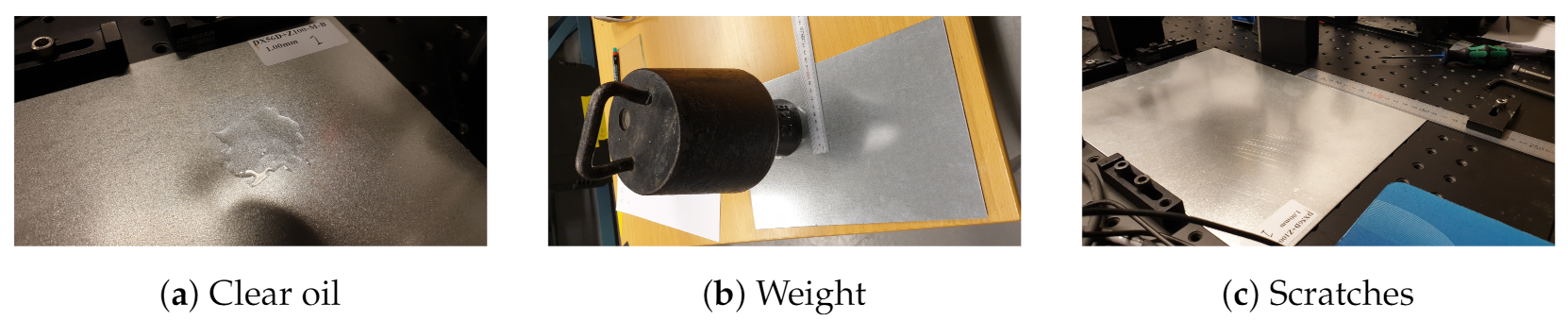
pixels was chosen and was correlated with each of the references stored. The detection was performed once a week with the camera and laser turned off in between occasions. Between each detection campaign, the sheets were stored separately. After the five weeks of quarantine, a surface alteration campaign started; see
Figure 2 for examples. To investigate the susceptibility to surface lubrication, a patch of approximately 1 mm deep clear oil was applied to each of the plates, and a detection was made; see
Figure 2a. In these experiments, the oxidized surface was excluded as that surface was considered to be too sensitive. Instead, the oxidized surface was rubbed with a clean cotton cloth before final detection, a treatment none of the other surfaces was tested for specifically. After the detection with the thick patch of oil, each surface was first cleaned with a piece of cotton cloth and later cleaned with heptan. After both of these cleaning steps, the surface was re-detected. In the next step, the surface was loaded by a weight that applied a total average pressure of 23 kPa on the surface; see
Figure 2b. The pressure was kept for 1 min to allow for the potential plastic deformation of surface asperities to appear. After the treatment, each of the sheets was re-detected. For this investigation, the copper, brass, and oxidized sheets were excluded. In the case of the copper and brass sheets, they were too thin and therefore too easy to deform when applying the weights. For the case of the oxidized surface, it was too sensitive to be included. In the last test, the susceptibility to scratches was tested; see
Figure 2c. For these tests, only the steel sheets were considered as they were considered to be the most interesting for these types of surface alterations. A piece of abrasive paper (quartz grain quality 100) was put underneath the weight in
Figure 2d and was dragged over the plate once. This procedure produced clearly visible scratches that were deemed unacceptable by an expert on the surface treatment of steel sheets, but were otherwise not quantified. The purpose of the different tests was to emulate damages that would appear naturally during transportation, where often, plates are given a protective layer of oil, stacked, and then transported to a different location for further treatment.
The setup for experiments on pipes is shown in
Figure 1b. Two different sizes were considered having diameters of 20 mm and 6 mm, respectively, for the purpose of investigating the susceptibility to different geometries. Two each of these pipes were investigated. The experimental procedure was the same as for the sheets. First, each of the four pipes was registered in the axial direction, and between each registration, the pipe was moved approximately 9 mm, giving in this case ten registrations per pipe. The central slice of 164 × 25,320 was stored as a reference for each of the pipes. Because of the curvature of the pipes, the light distribution detected by the camera became severely elongated along the axial direction of the pipes, making the choice of a slice width of 164 pixels a rather natural one. This was particularly true for the 6 mm diameter pipes. The pipes were then mixed at random and stored together for a week. Once a day, the pipes were re-detected and re-mixed. Hence, four different detection campaigns were performed. During detection, an axial position was chosen at random, and images were acquired every 20 min of a degree for a full revolution. Hence, one-thousand-eighty images were recorded per pipe. For each image, the central
subpart was chosen and was correlated with the stored reference images. The results from these investigations are summarized in
Table 3.
3. Results
The results from the tests are summarized in
Table 3. The first column refers to the sheets specified in
Table 1, and the results from the two pipes are summarized as p6 and p20, respectively. In each of the remaining columns, two numbers are given. The first number is the maximum correlation value
given by Equation (
1) averaged over the domain of detection. For each of the detections, the match was considered a success provided
. When summarized, a detectability number is obtained, which is given by the second number. A value of 100 means that all patterns where successfully matched, and zero means that no matching pattern could be found. It is seen from the results that in general, a good match was found with a correlation value in the order of 0.9 or higher, indicating a high degree of similarity. In this context, it is also worth mentioning that the correct component was indeed detected in all cases indicated in
Table 3. No false positives were obtained. When looking through the numbers, a few points should be pointed out. First, one drop-out was obtained from the copper plate in one measurement point on one occasion. The reason for this drop-out is most likely due to the thin material that had a tendency to buckle when manually placed in the measurement position. Since speckle patterns are known to decorrelate easily in response to a surface tilt, that drop-out is probably caused by misalignment rather than changes in the object surface. However, the sensitivity of the technique for macroscopic alterations of the surface is understood from the relatively lower correlation values on average for the thin copper plate. A second observation is that a thick layer of transparent oil changes the speckle pattern completely, and the correlation values are comparable with those between two uncorrelated speckle patterns. The detectability was zero for those cases. When cleaned with a cloth, the correct speckle pattern reappeared, and when cleaned again with a solvent, the speckle correlation returned to its original values. Hence, cleaning did not influence the matching, which has many practical implications. When turning to the mechanical impact of the surfaces, first, loading did not significantly change the correlation values, and a positive match was found for all cases. It may come as a surprise that the speckle patterns generated were relatively robust against the irreversible plastic deformations of asperities, but in fact these, would only make up a very small portion of the light scattered off the surface, while their collective impact would be minor. The same can be said about the scratches. Visually, the scratches changed the surfaces completely, and sheets that appear at the customer in that condition would most likely be put in the scrap bin. However, at a microscopic level, inside the Airy spot, the scratches would only make up a very small part of the scattering surface, with the remaining parts left intact. In contrast, when rubbing the powdery oxidized surface with a cloth, particles were worn off, and the micro-topography of the surface changed completely. The result was a loss in detectability.
4. Discussion
The results presented in
Table 3 indicate that laser speckles may be used as secure and efficient natural markings of metallic components that are traceable after normal treatment of the components. In this paper, it is considered that for registration, the component is scanned along a line throughout the length of the component, and the merged images thus obtained are stored as a unique fingerprint for the component. The advantage of this approach is that a unique sub-pattern exists for every part of the component, which means that the sheet or pipe may be cut into pieces and still be traced back to the original item. That this is possible is indicated in the second column in
Table 3, where despite that the position along the component was chosen at random, the correct component was detected. The disadvantage is that an excessive amount of data has to be stored for each component. For the detection only, a subimage of size
pixels was used, and the search domain was as large as 164 × 70,000 pixels for each component, which indicates a potential for a significant data reduction provided the registration is limited to a restricted area. The fact that a subimage as small as
pixels contains enough unique features for the detection is attributed to the nature of laser speckles [
5]. The generation of laser speckles can be seen as a low-pass filtering of white noise where the cut-off frequency is set by the
f-number of the imaging. In the present case, the aperture was chosen such that a unique correlation cell is three pixels. Hence, the subimage will contain approximately 400 correlation cells with a unique shape, orientation, and distributions that ultimately depend on the local micro-structure of the surface. The probability that a similar pattern should appear by chance is very small, which has the great advantage that the probability of a false positive detection is almost infinitely low. This makes a laser speckle pattern almost impossible to copy.
The measures presented in
Table 3 were calculated by Equation (
1). This formulation has several advantages, as it is relatively straight forward to implement, has a clear connection with physics, and is known to be robust. It does have a number of disadvantages though. One disadvantage is that it is calculation intense, which may prevent any practical applications larger than a few hundreds of components. This limitation can be reduced if the correlation instead is performed in the Fourier domain [
12]. However, such a choice does not solve the problem that a correlation calculation in its basic form is not rotation invariant, which becomes a practical problem particularly for sheets. To account for possible rotations, additional freedoms have to be introduced. The correlation is not the only algorithm that can be used for fingerprinting. Inspired by algorithms frequently used in computer graphics, Charrett and Tatam investigated the use of various feature based techniques for the estimation of speckle motions, techniques that also provide information about the similarity of the patterns [
13]. The great advantage of such techniques is that they allow a significant amount of data reduction and that possible rotations and magnification shifts are implicitly included. They are also in general significantly more calculation efficient. However, there are still questions of how robust these techniques are in response to speckle decorrelations, and additional investigations are required to get a better understanding of the domain in which feature based techniques can be utilized for fingerprinting involving laser speckles.
A laser speckle pattern is relatively robust to moderate micro-structural alterations of the scattering surface [
4], a fact that also is seen in the results in
Table 3. The reason for this robustness is that the formation of a speckle pattern can be seen as a summation of a large amount of wavelets that adds up to the resulting complex amplitude. As long as the majority of the wavelets remain unchanged or are only slightly modified, the probability to end up with a complex amplitude in the vicinity of the original one is relatively high. This is the reason the detectability in Columns 6 and 7 in
Table 3 remains high. A scratch, for example, may only alter about 10-20% of the local scattering surface, resulting in a high correlation despite the obvious damage to the surface. This relative robustness is also the reason laser speckles have such great applicability in metrology [
6]. However, if all the individual wavelets change, the result is a gradual change of the speckle structure and eventually a new speckle pattern that shares no similarity with the original appearance. This happened for the oxidized surface where the rubbing wore off particles and thereby changed the scattering signature from the surface completely. It also happened when a thick layer of clear oil was put on the surface. In this latter case, refraction at the oil surface and the change in wavelength caused by the refractive index of the oil made a significant change that deteriorated the phase response of the surface. The scattering signature was, however, restored when the oil was cleaned off. How much damage the surface can withstand before the speckle patterns become uncorrelated is an interesting question that was investigated by Fricke-Begemann et al. for the case of corrosion [
9]. In their investigation, they found that topography changes in the order of 5% of the wavelength will generate a speckle decorrelation of roughly 50%. This indicates that some corrosion may be acceptable without destroying the detectability, but that care has to be taken to ensure that a new registration is performed before the surface has undergone significant surface alterations.
If a speckle pattern is robust to small micro-structural surface alterations, the same cannot be said about alterations in the imaging geometry. In fact, small surface tilts can result in complete speckle decorrelation, particularly at large imaging
f-numbers [
5]. The slightly lower correlation values for the sheets in the second column in
Table 3 as compared to those of the pipes can be attributed to this effect. Despite the fact that the pipes were rotated and a perfect alignment between registration and detection cannot be guaranteed, the clamping of the pipes generated a more stable outcome as compared with the sheets that were positioned by hand. Care therefore has to be taken to make sure that the relative orientation of the surface does not change significantly between registration and detection, which in this case was secured for the pipes by making the detection in steps of a third of a degree. Speckle motion based decorrelations have been thoroughly investigated [
14,
15]. Speckle motions are generated for any change in the imaging properties including surface rotations and strain, the tilt of the illumination direction, and a change in wavelength, which generates a shift of the field across the entrance pupil of the imaging. As a result, the speckles decorrelate where complete decorrelation appears for shifts larger than the diameter of the entrance pupil. However, for a setup using normal illumination, the speckles are relatively robust to in-plane strains and wavelength shifts. The reason is that the field in these cases will change the divergence rather than the direction of the field, and as a result, the speckles are shifted in the depth direction rather than laterally. This is an important observation that will make the speckle structure reasonably robust against strain and hence changes in temperature between registration and detection. As long as the illumination and observation angles remain the same, a successful detection is therefore limited by the ability to perform the detection at the same angle as during the registration.
Finally, we give a few words about the coherence requirements of the light source. For the experiments reported in this paper, a TEM
monochromatic laser was used, which guarantees coherent illumination across the field-of-view and, therefore, dependent on the surface structure, the generation of speckles with unit contrast. However, the generation of high-contrast speckles only requires the illumination to be spatially coherent across the Airy spot of the imaging, which opens up the possibility to use light sources with significantly lower spatial coherence. For example, for the experiments in this paper, the requirement was a spatial coherence width of approximately 10 μm. The requirement on the spectral bandwidth will depend on the surface roughness, but typically, the correlation width is in the order of a few nm [
5]. In general, therefore, the requirement on the longitudinal coherence is more strict than the requirement on the spatial coherence. On the other hand, an interesting question that has not been investigated in this paper is the speckle contrast required for the technique to be successful. In principle, a correlation calculation can be successfully performed for a feature contrast as low as 10% or less, which indicates that fingerprinting can be applied for averaged speckles and hence for applications using a much wider range of light sources. Whether this possibility opens up new and more versatile applications is left for future research.
5. Conclusions
In this paper, the robustness of image-plane laser speckles for use as unique patterns for fingerprinting is investigated. The materials considered are solid surface scattering metal surfaces including steel, aluminum, brass, and copper in the form of sheets and pipes. Surface alterations in the form of zinc plating, painting, oxidation, and acid treatment are also considered. The surfaces are subjected to oil coverage, surface compression, scratching, and cleaning to mimic the situations most likely to appear in the real world. It is found that all surfaces but the heavily oxidized surface are robust against the treatment considered and that a unique fit is found. No differences related to the surface geometry are found. The limit set for a positive match is a correlation value of 50%. A degradation of this magnitude is reached if 50% of the scattering surface is changed, which can happen if the surface is damaged by scratching or if the surface pressure is so high that more than half of the surface asperities are plastically deformed. None of this happens in the measurements performed, where a maximum decorrelation of 10% is reached for both of these situations. Another type of surface alteration is corrosion, which alters the scattering phase function from the surface homogeneously, where it is estimated that a surface alteration of 5% of a wavelength or more would result in an undetectable surface. Surface alterations larger than this level are obtained for the oxidized surface when cleaned with a cotton cloth and when a thick layer of clear oil is put on the surfaces. However, the original speckle patterns reappear after cleaning the surface, which indicates that the fingerprint remains intact after the steps of treatments provided the clean surface is not altered more than 5% of a wavelength. The detection is sensitive to the alignment between the surface normal and the optical axis of the imaging system. In fact, a tilt angle as small as , where is the f-number of the imaging, will result in an undetectable pattern. For the experiments performed in this investigation, that corresponds to a tilt angle of 60 mrad. Care therefore needs to be taken to ensure detection along the same direction as the one used for registration. In contrast, the technique is robust against in-plane strain and hence changes in temperature. The reason for this is that strain will move the speckle pattern predominantly in the depth direction, a direction for which a speckle pattern at these high f-numbers is relatively robust. With the experiments performed in this investigation, it is demonstrated that laser speckles can be used as unique features for secure fingerprinting of solid metal components, even for moderate surface alterations. Future investigations should include the possibility to replace image correlation as the detection algorithm and the possibility to reduce the amount of data stored for more efficient handling.


