
Hydrogen Sulfide Removal from Flare Gas


Petroleum Research Center, Kuwait Institute for Scientific Research, Ahmadi, Safat 13109, Kuwait
Gases 2026, 6(2), 22; https://doi.org/10.3390/gases6020022
Submission received: 6 April 2026
/
Revised: 28 April 2026
/
Accepted: 3 May 2026
/
Published: 7 May 2026
Abstract
Flaring is necessary to prevent pressure buildup in the unit. Due to hydrotreatment processes at the refinery, flare gas can contain significant amounts of hydrogen sulfide. Combusting this gas can result in environmental and health issues. One method to reduce hydrogen sulfide is to replace the water in the seal drum with an amine solution. Honeywell UniSIM® process simulation was used to calculate the hydrogen sulfide removal efficiency with 45 wt% MDEA solution. Results show that removal efficiency depends on amine loading and pool height. Removal efficiency of up to 72.5% was achieved with a hydrogen sulfide-to-amine molar loading of 0.2 (4:20 ratio) and a pool effective height of 2.5 m.
1. Introduction
Hydrotreatment is one of the major processes at the refinery to remove sulfur from fuels using pressurized hydrogen [1]. This results in a concentrated hydrogen sulfide stream that is sent to a sulfur recovery unit to convert hydrogen sulfide into solid sulfur [2]. However, during emergency situations, the stream is sent to a flare unit to prevent pressure buildup at the unit [3].
The flare system consists of a drum through which the gas passes a pool of water before going to the stack. The purpose of water is to prevent the flame from returning to the process, also known as flashback [4]. At the top of the stack, the gas will be flared and hydrogen sulfide is converted to sulfur dioxide. It is known that sulfur dioxide harms the environment by forming acid rain that can damage the wild and sea life [5]. Furthermore, sulfur dioxide can affect the respiratory and cardiovascular systems [6].
The flare gas can contain a serious amount of hydrogen sulfide that need to be removed [7]. However, it is difficult to treat flare gas using current technologies because the gas flow can be blocked, leading to serious situations. Furthermore, technologies such as membranes and pressure swing adsorption will require capital investment, operational cost, and additional space for installation and integration.
One of the solutions, according to a recent patent, is to replace the water in the liquid seal drum with amine [8]. The amine can prevent flashback and remove some hydrogen sulfide simultaneously. This innovative solution is easy to implement, as no additional equipment or space is required. Furthermore, the amine can be reused using the available regeneration unit in most refineries, thereby eliminating the need for capital investment.
Methyldiethanolamine (MDEA) is one of the widely used amines for hydrogen sulfide removal due to its higher efficiency and lower regeneration energy compared to other amines [4]. Table 1 compares the physical properties of water with 45 wt% methyldiethanolamine (MDEA). The amine has a higher boiling point of 170 °C and a lower freezing point of −32 °C. This gives the amine a broader operational range than water. However, the amine may require special drum material to prevent corrosion. Furthermore, the amine has a higher operational cost.
Unfortunately, the patent does not provide details on the properties of the flare gas or the amine’s operating conditions. Furthermore, no information was provided about the sizing of the liquid seal drum. These data are critical to accurately determine the removal efficiency.
In this work, the water in the liquid seal drum was replaced with MDEA solution, and the hydrogen sulfide removal efficiency from the flare gas was estimated. Honeywell® UniSIM® (R500) (Honeywell, Charlotte, NC, USA) was used as the simulation software. Removal efficiency was calculated based on different pool heights. The amine flow rate was also adjusted at different hydrogen sulfide-to-amine loadings to examine the effect on the removal efficiency.
2. Methodology
The absorption of hydrogen sulfide into the amine solution is described by the following fast reaction [10]:
The reaction is also controlled by the mass transfer resistance where hydrogen sulfide molecule must diffuse through the gas–liquid interface to reach the amine [11]. To take into account the previous limitation, the liquid seal drum was modeled in UniSIM® using a rate-based absorber [12] with one stage of separation. The flare gas is mainly hydrogen and methane, with a hydrogen sulfide concentration of 10 mol% [13]. The flow rate is 100 Nm3 h−1 at 40 °C and atmospheric pressure. The amine is based on MDEA with a concentration of 45 wt%, as used by many refineries [14]. The amine temperature was 45 °C, above the flare gas temperature, to prevent hydrocarbon condensation [15]. The amine pressure was maintained at 1.1 bar, which is 10% above the flare gas pressure [16]. The amine flow rate was set using the recommended hydrogen sulfide-to-amine molar loading of 0.2 to 0.4 [17]. Table 2 shows the operating conditions used for the flare gas and the amine.
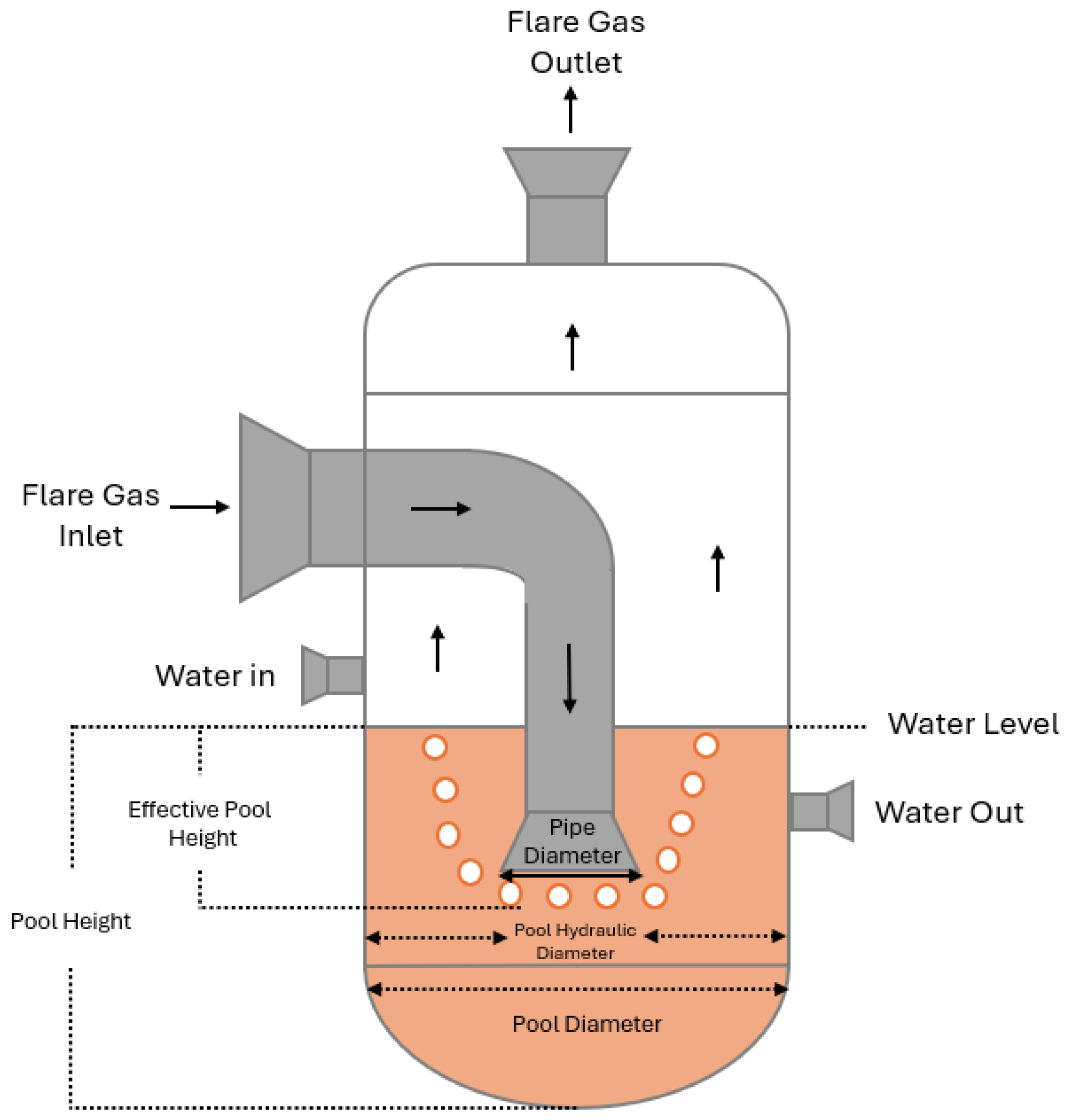
Figure 1 shows a typical seal drum design where the flare gas is injected into the pool through an immersed pipe. The drum diameter is assumed to be 1 m, and the inlet gas pipe diameter is 0.5 m. Because the flare gas is fed at low pressure, the gas bubbles are expected to leave the pool instantly without reaching the pool floor due to buoyant force, as demonstrated in Figure 1. This means that the gas will travel through the area between the drum wall and the inlet pipe, which gives a hydraulic diameter of 0.5 m. Similar to the diameter, the effective pool height is not the total height of the liquid in the drum; instead, it is measured from the bottom of the inlet pipe where the bubbles leave to the liquid surface, as shown in Figure 1. To study the effect of pool height on hydrogen sulfide removal efficiency, the effective pool height was varied from 0.5 to 2.5 m. Hydrogen sulfide removal efficiency was calculated by based on the molar flowrate of hydrogen sulfide in the inlet and outlet gas streams:
3. Results and Discussion
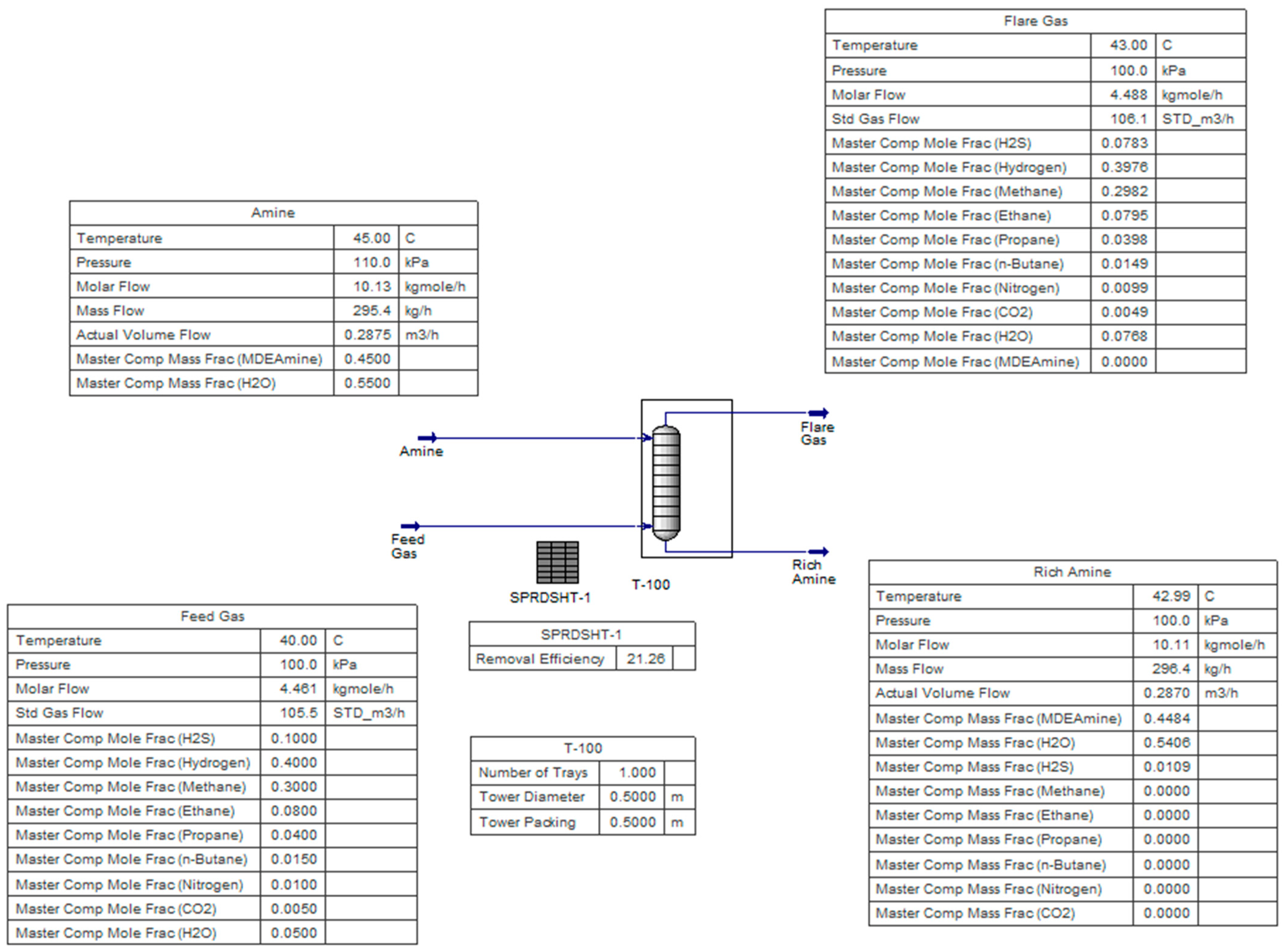
The simulation was run using different MDEA flowrates from 0.29 m3 h−1 to 0.58 m3 h−1 based on the hydrogen sulfide-to-amine molar loadings of 0.4 to 0.2, respectively. First, the effective pool height was fixed at 0.5 m to study the effect of MDEA flowrate. Figure 2 shows the solved case at the lowest flowrate of 0.29 m3 h−1 (0.4 loading), which gives a removal efficiency of 21.3%. Increasing MDEA flowrate to 0.58 m3 h−1 (0.2 loading) significantly improved the removal efficiency to 34.8%. It was expected that increasing the amine flow rate (decreasing the molar loading) would improve the removal efficiency, as there would be more MDEA molecules available to remove additional hydrogen sulfide. It is not suggested to increase the amine flowrate further as this will result in a corrosive stream that can damage equipment [17].
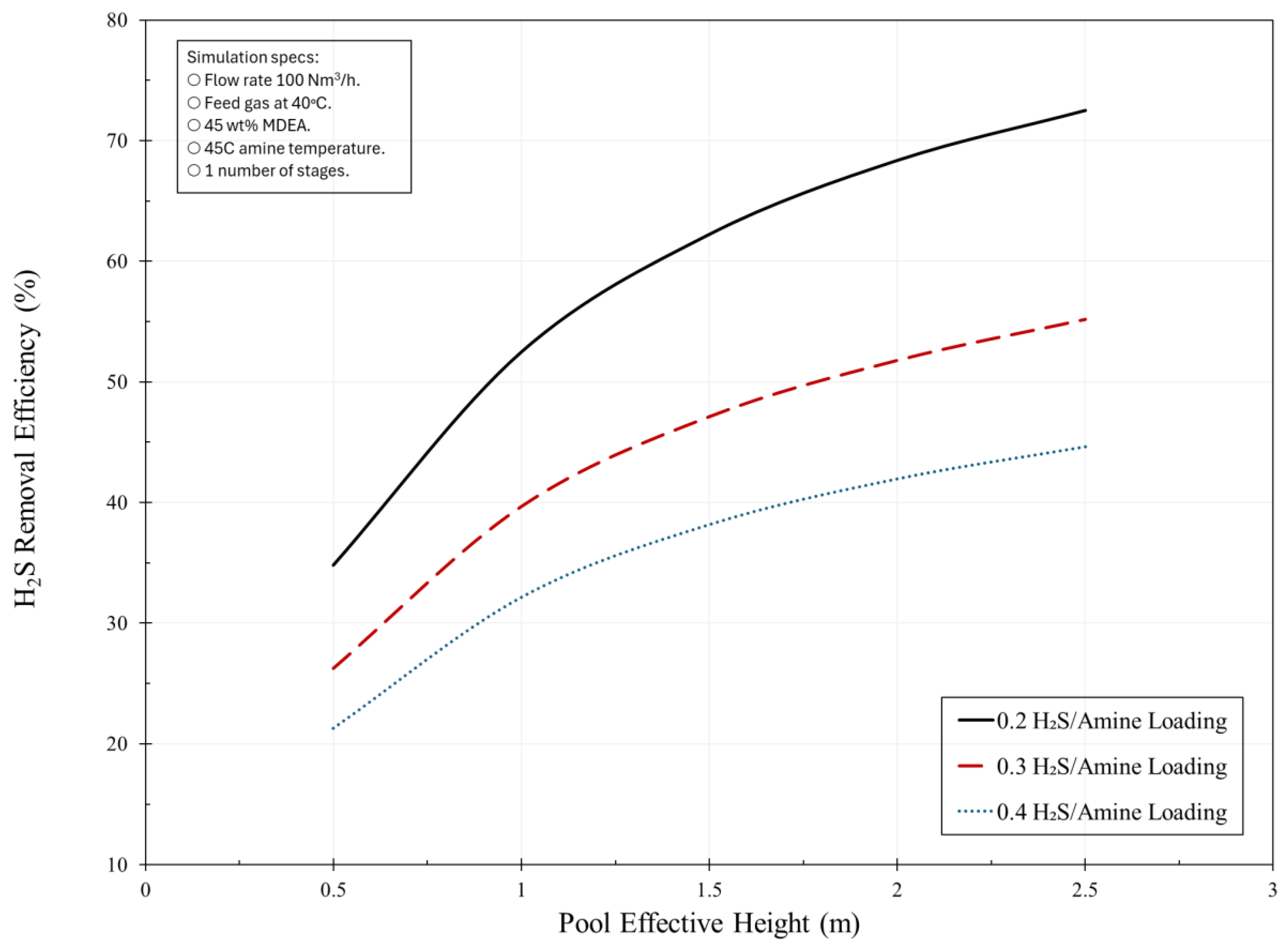
The second way to improve removal efficiency is to expand the effective pool height. The MDEA flowrate was fixed at 0.58 m3 h−1 (0.2 loading) while the height was changed from 0.5 to 2.5 m. At a pool height of 1 m, the removal efficiency increased from 34.8% to 52.5%. When using a height of 2.5 m, a maximum efficiency of 72.5% was achieved. This means that the hydrogen sulfide content in the flare gas was reduced from 10% to 2.8% using only MDEA solution. This will notably reduce sulfur dioxide emissions. The overall results are shown in Figure 3. The improvement in removal efficiency with pool height can be attributed to an extended residence time, as the gas bubble takes a longer path to reach the surface. Also, the hydrostatic pressure for higher pools is expected to increase due to the added force exerted by the amine. This will increase the partial pressure of hydrogen sulfide for better removal.
However, it is expected that further increasing the effective pool height will not significantly improve removal efficiency, as the logarithmic line approaches a nearly constant value (Figure 3). Moreover, most liquid seal drums have limited space due to the internal parts. It should be noted that a regeneration step is required to remove hydrogen sulfide from the amine solution. This can be achieved by increasing the temperature of the amine solution to 100–120 °C using a multi-stage tower [18]. Nevertheless, most refineries have an amine regeneration tower, so the stream can be easily regenerated without requiring additional capital investment for the tower.
It is also worth noting that the above results for hydrogen sulfide removal efficiency remain theoretical because many parameters were not considered, including bubble size, residence time, and interfacial area. Moreover, the presence of light hydrocarbons may form a thin film on the MDEA solution, thereby disrupting the gas–liquid interface. Experimental data are necessary to validate the findings. Furthermore, the rich amine solution containing hydrogen sulfide may cause corrosion to carbon steel. Actually, the amine solution containing hydrogen sulfide will form a protective film of iron (II) sulfide (FeS). However, due to high gas velocities, the layer can be destroyed, exposing the bare metal [19]. Therefore, implementation of corrosion mitigation measures may be necessary.
4. Conclusions
The flare gas usually contains hydrogen sulfide due to the hydrotreatment processes in the refinery. Combusting this stream will produce sulfur dioxide, which is known to cause environmental and health issues. It is difficult to treat flare gas using conventional methods because there is a risk of blocking the gas flow, which could lead to serious consequences. A recent patent recommended replacing water with the amine at liquid seal drum to prevent flashback and remove hydrogen sulfide. However, the patent omits key information needed to accurately estimate removal efficiency, such as flare gas properties and amine operating conditions. In this work, the removal efficiency was calculated using UniSIM® process simulation. The effects of hydrogen sulfide-to-amine loadings and pool height were studied. The minimum removal efficiency was 21.3% at a 0.4 loading with a pool height of 0.5 m. The maximum efficiency of 72.5% was achieved with a loading of 0.2 and a pool height of 2.5 m. This removal efficiency will significantly reduce sulfur dioxide emissions. Nevertheless, experimental data are required to confirm the results are there are many parameters that were not taken into consideration such as bubble size, residence time, and condensation of light hydrocarbons.
Funding
The project was funded by the Kuwait Institute for Scientific Research (KISR) under the code PF112K.
Data Availability Statement
Dataset available on request from the author.
Conflicts of Interest
The author declares no conflicts of interest.
References
- Speight, J. Hydrotreating and Hydrocracking Processes in Refining Technology; CRC Press: Boca Raton, FL, USA, 2023. [Google Scholar]
- Hsu, C.; Robinson, P. Handbook of Petroleum Technology; Springer: Berlin/Heidelberg, Germany, 2017. [Google Scholar]
- Daun, K.; Spinti, J. Techniques for measuring flare combustion efficiency and destruction removal efficiency: A review. Prog. Energy Combust. Sci. 2025, 110, 101235. [Google Scholar] [CrossRef]
- Stewart, M. Surface Production Operations: Vol 2: Design of Gas-Handling Systems and Facilities; Gulf Professional Publishing: Houston, TX, USA, 2014. [Google Scholar]
- Lane, C. Acid Rain: Overview and Abstracts; Nova Science Publishers: Hauppauge, NY, USA, 2003. [Google Scholar]
- Izah, S.; Ogwu, M.; Shahsavani, A. Air Pollutants in the Context of One Health: Fundamentals, Sources, and Impacts; Springer Nature: Cham, Switzerland, 2024. [Google Scholar]
- Szpalerski, J.; Smoliński, A. Analysis of the excess hydrocarbon gases output from refinery plants. Processes 2019, 7, 253. [Google Scholar] [CrossRef]
- Rathinasabapathi, K. Amine Liquid Seal in a Flare System. U.S. Patent 12,157,086, 3 December 2024. [Google Scholar]
- Speight, J. Shale Oil and Gas Production Processes; Gulf Professional Publishing: Houston, TX, USA, 2019. [Google Scholar]
- Qian, Z.; Xu, L.-B.; Li, Z.-H.; Li, H.; Guo, K. Selective absorption of H2S from a gas mixture with CO2 by aqueous n-methyldiethanolamine in a rotating packed bed. Ind. Eng. Chem. Res. 2010, 49, 6196–6203. [Google Scholar] [CrossRef]
- Ma, M.; Zhao, M. Investigation into the enhancement of gas–liquid mass transfer of absorption of H2S by MDEA with carbon quantum dots. ACS Omega 2023, 8, 34678–34686. [Google Scholar] [CrossRef] [PubMed]
- Zhu, W.; Ye, H.; Yang, Y.; Zou, X.; Dong, H. Simulation-based optimization of a multiple gas feed sweetening process. ACS Omega 2022, 7, 2690–2705. [Google Scholar] [CrossRef] [PubMed]
- Merriman, D. Maintain Compliance to Petrochemical (EMACT) and Organic Chemical Sector (MON) Flare Gas Rules with Rapid Online Analysis by Prima PRO Mass Spectrometers; Thermo Fisher Scientific: Horsham, UK, 2020. [Google Scholar]
- Pal, P.; AbuKashabeh, A.; Al-Asheh, S.; Banat, F. Role of aqueous methyldiethanolamine (MDEA) as solvent in natural gas sweetening unit and process contaminants with probable reaction pathway. J. Nat. Gas Sci. Eng. 2015, 24, 124–131. [Google Scholar] [CrossRef]
- Shahouni, R.; Akrami, M. A comprehensive review on control and mitigating the foam formation in amine-based solvents. Chem. Eng. J. Adv. 2024, 19, 100618. [Google Scholar] [CrossRef]
- Jamekhorshid, A.; Davani, Z.; Salehi, A.; Khosravi, A. Gas sweetening simulation and its optimization by two typical amine solutions: An industrial case study in Persian Gulf region. Nat. Gas Ind. B 2021, 8, 309–316. [Google Scholar] [CrossRef]
- Stewart, M.; Arnold, K. Gas Sweetening and Processing Field Manual; Gulf Professional Publishing: Houston, TX, USA, 2011. [Google Scholar]
- Hack, J.; Maeda, N.; Meier, D. Review on CO2 capture using amine-functionalized materials. ACS Omega 2022, 7, 39520–39530. [Google Scholar] [CrossRef] [PubMed]
- Sheilan, M.; Spooner, B. Iron sulphides—Friends or foe? Revisited. In Proceedings of the GPA Midstream Annual Convention, San Antonio, TX, USA, 21–24 September 2025. [Google Scholar]
Figure 1.
Typical design of liquid seal drum and the measurements of effective pool height and equivalent diameter.
Figure 1.
Typical design of liquid seal drum and the measurements of effective pool height and equivalent diameter.

Figure 2.
Solved case in UniSIM® to calculate hydrogen sulfide removal efficiency from the flare gas using hydrogen sulfide-to-amine loading of 0.4 and effective pool height of 0.5 m.
Figure 2.
Solved case in UniSIM® to calculate hydrogen sulfide removal efficiency from the flare gas using hydrogen sulfide-to-amine loading of 0.4 and effective pool height of 0.5 m.

Figure 3.
Effect of MDEA loading and effective pool height on hydrogen sulfide removal efficiency.


Table 1.
Comparison between water and amine (MDEA) as a liquid in a seal drum [9].
Table 1.
Comparison between water and amine (MDEA) as a liquid in a seal drum [9].
| Property | Water | MDEA (45 wt%) |
|---|---|---|
| Purpose | Flashback prevention | Flashback prevention and H2S removal |
| Boiling point | 100 °C | 170 °C * |
| Freezing point | 0 °C | −32 °C * |
| Flash point | NA | ~127 °C |
| Corrosion rate | Lower | Higher |
| Operational Cost | Lower | Higher |
* Calculated using process simulation.
Table 2.
Properties of flare gas and MDEA solution.
| Property | Value | ||
|---|---|---|---|
| Flare Gas Temperature | 40 °C | ||
| Flare Gas Pressure | 1 bar | ||
| Flare Gas Flowrate | 100 Nm3 h−1 | ||
| Flare Gas Composition | |||
| H2S | 10 mol% | C4 | 1.5 mol% |
| H2 | 40 mol% | CO2 | 0.5 mol% |
| C1 | 30 mol% | N2 | 1 mol% |
| C2 | 8 mol% | H2O | 5 mol% |
| C3 | 4 mol% | ||
| Amine Temperature | 45 °C | ||
| Amine Pressure | 1.1 bar | ||
| Amine Flowrate | 0.2–0.4 H2S/MDEA loading | ||
| Pool Diameter | 0.5 m | ||
| Pool Height | 0.5–2.5 m | ||
Disclaimer/Publisher’s Note: The statements, opinions and data contained in all publications are solely those of the individual author(s) and contributor(s) and not of MDPI and/or the editor(s). MDPI and/or the editor(s) disclaim responsibility for any injury to people or property resulting from any ideas, methods, instructions or products referred to in the content. |
© 2026 by the author. Licensee MDPI, Basel, Switzerland. This article is an open access article distributed under the terms and conditions of the Creative Commons Attribution (CC BY) license.
Share and Cite
MDPI and ACS Style
Alqaheem, Y. Hydrogen Sulfide Removal from Flare Gas. Gases 2026, 6, 22. https://doi.org/10.3390/gases6020022
AMA Style
Alqaheem Y. Hydrogen Sulfide Removal from Flare Gas. Gases. 2026; 6(2):22. https://doi.org/10.3390/gases6020022
Chicago/Turabian StyleAlqaheem, Yousef. 2026. "Hydrogen Sulfide Removal from Flare Gas" Gases 6, no. 2: 22. https://doi.org/10.3390/gases6020022
APA StyleAlqaheem, Y. (2026). Hydrogen Sulfide Removal from Flare Gas. Gases, 6(2), 22. https://doi.org/10.3390/gases6020022