1. Introduction
Often, in the calculation of engineering structures, the action of the wind load is taken as a static load based on the design procedures [
1]. To perform dynamic calculation from the action of the wind, it would be necessary to predict the dynamic cycle of loading, accurately determining all the dynamic parameters of the wind load. Taking them into account will make it possible to obtain the correct loading of each element of the structure and to find the real reason for the destruction of the object excited by the force of the wind, that is, destruction from a loss of solidity or due to rigidity, vibrations, failure or fatigue.
As for the static loads, their determination is relatively easy since their data are obtained through standards [
2] for specific areas, different heights of structures, structural factors, etc. Conversely, the dynamic load [
3,
4] is more difficult to determine since the recognition of the cyclic characteristics of the wind load is more difficult.
In this article, referring to the wind data obtained from the static loads and the factors for calculating the wind speed, we will further analyse the dynamic loads. What is new in this article is the practice of determining the characteristics of the load cycle from the dynamic action of the wind in different structures. The maximum load, minimum load, amplitude load, and the characteristics of the load cycle (load ratio) [
5] are quantities that will be determined as normalized and then used for other calculations by different engineers. Also, through the accumulation method of the damage, we will determine the lifespan of a structure from the dynamic action of the wind [
6,
7].
2. Static Load from Wind Action
As mentioned above, the study of the load from the wind action has its own difficulties since the wind is a quantity that changes not only in the function of the geographical position of the structure but also in function of height. For engineering calculations, it is often recommended that practitioners use the tabular method of assessing the geographical area and height where the structure is as a more appropriate method compared to analytical methods.
Table 1 presents a material according to [
1], where the factor for the speed and average force for 3 s at a height of 10 m is given as a function of height.
So, the above data from the standards show the factors we must consider in order to perform the speed or wind force calculation at different heights. As seen above, there is considered to be an average speed or strength of 3 s. Based on the calculations of the machine elements [
8,
9], the average force is equivalent to a static force, and so the dynamic action of the wind [
10,
11] is not considered. Let us analyse these data further.
3. Dynamic Load from Wind Action
Starting from the wind speed, measured at the height of 10 m for 10 min, i.e., 600 s, the value meteorological stations give, it is possible to move to the instantaneous wind speed measured at the height of 10 m for 3 s (sometimes given as wind gust).
3.1. Average Wind Speed for 600 Seconds and 3 Seconds
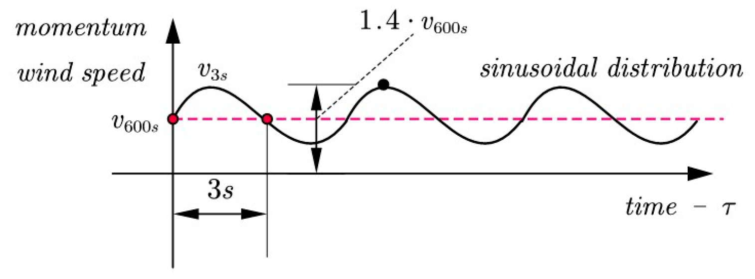
Calculating from the average speed measured by meteorological services for 600 s to the average speed for 3 s or, in special cases, to 1 s, can be performed by multiplying the average speed for 600 s by the coefficient. In this article, we consider sinusoidal distribution, as shown in
Figure 1. The coefficient 1.4 for 3 s or, in special cases, 1.51 for 1 s, which we consider in the dynamic calculation, is taken from the ISO standard (en1991.1.4.2005) [
1]. It is also worth emphasizing that the sinusoidal distribution shown in
Figure 1 is used for the general (almost ideal) case without considering the structure factors, c
s c
d, pressure coefficients for buildings, terrain effects, etc. This distribution is accepted as the theory of fatigue in machine elements [
5].
The equation for determining the wind speed per second will be:
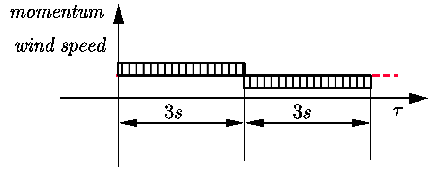
Analysing only for 3 s, we will have the distribution of the speed as shown in
Figure 2.
So, for the time 3 s, a part of the wind speed will be above the average value and the other part will be below the average. Based on this approximation, we draw the conclusion that the cycle period of the wind is s.
3.2. Active Forces in Costruction
The same reasoning applies to active force in the construction, which is a dynamic force and causes damage from vibrations and fatigue. Knowing the dynamic force expression, we will write:
where
is structure form factor,
is the projected surface in the wind direction.
Average force
can be determined from the wind speed
as above:
Then the maximal dynamic force can be determined as:
The amplitude force for further calculation, such as fatigue calculation, and the minimal dynamic force can be expressed as:
Now, we can also calculate the cyclic loading characteristic
.
We see that this characteristic is almost zero, which means that we are in the case of loading with the pure pulsating cycle of the mechanical structure.
3.3. Swing Period
The period of this speed oscillation was taken to be
. By analogy with the theory of vibrations, we can find the circular frequency of the excitation force:
and the wind speed will be written in the form:
3.4. Active Impulse from the Wind Action
From the pulse and momentum theorem we obtain:
where
is object mass, and
and
are the velocity of the mass before and after the action of the wind force. As well as knowing the dynamic force expression from Equation (3), we can derive the active impulse as follows:
An object at rest under the influence of the active force of the wind and a constant resistance force R, such as sliding or rolling friction, will gain speed
4. Case Study
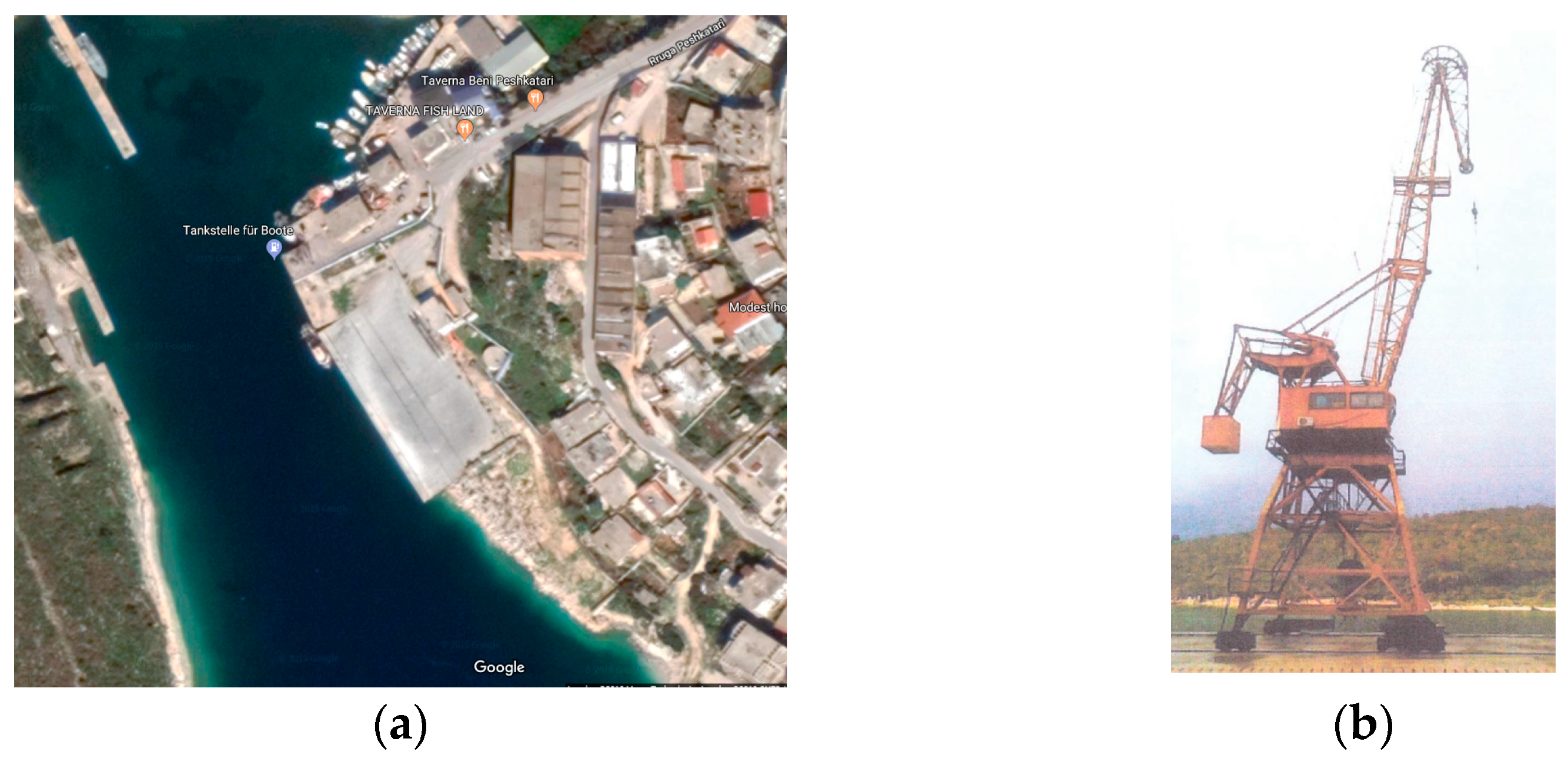
In the following section, we will briefly show a case study for the calculation of the minimum force caused by the wind that can move a port crane. As mentioned at the beginning, the characteristics of the surface of the structure, the mass of the GANZ 50 kN portal crane, as shown in
Figure 3, and the equivalent wind coefficient were obtained according to [
3] and are shown in
Table 2.
Based on the above dynamic analysis for these characteristics found, it is possible to calculate the minimum wind speed that starts the crane movement after the forces of resistance have been overcome (unwanted case, accident, falling into the sea even though there was a mechanical stop).
This speed is the critical wind speed for this crane, which could move if it were not equipped with a braking system (free state). This speed is equivalent to a wind force that will overcome the wind’s rolling resistance.
Change of Wind Diraction Action
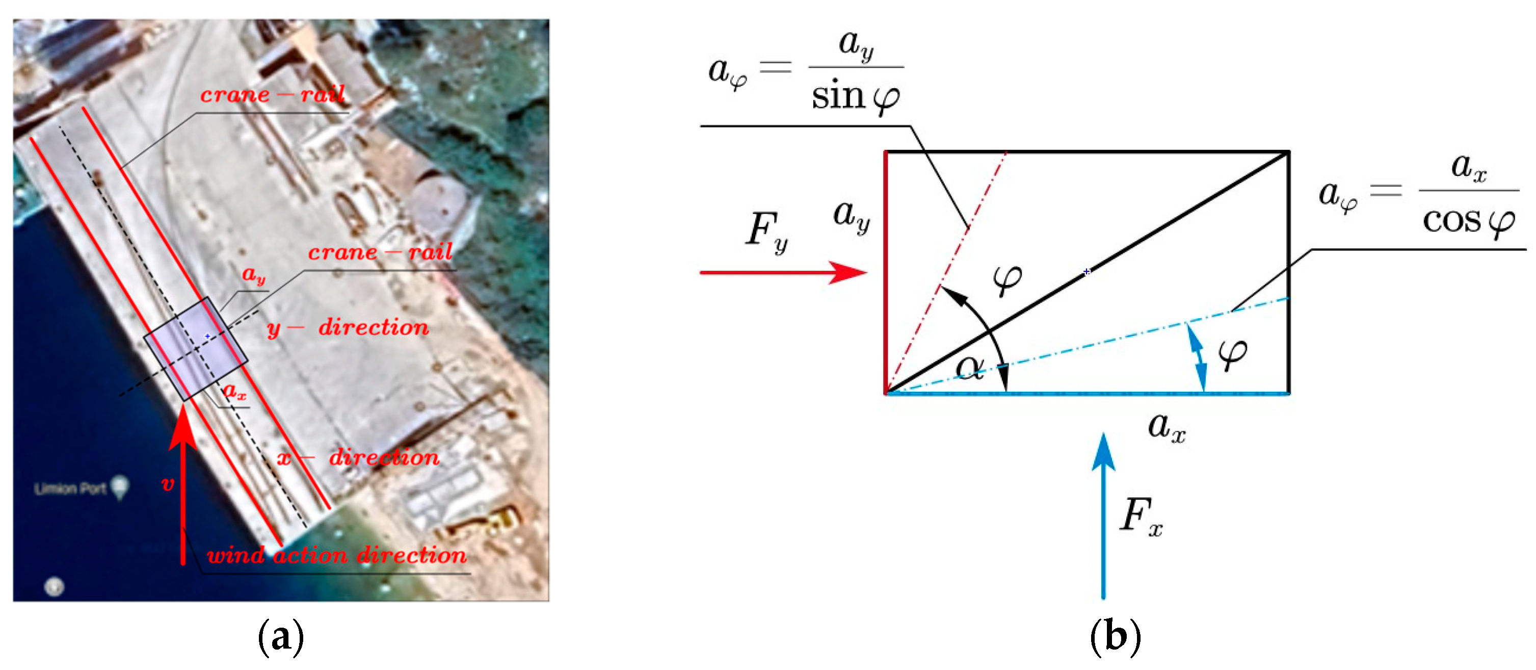
The crane has two possibilities of movement: parallel to the rails or in the direction that does not move, which is perpendicular to the rails. So, the direction of the wind plays an important role because we require the component of the wind force in the direction of movement to be greater than the resistance forces of movement (or the equivalent wind speed found above). In the specific case examined, the wind speed was greater before the event, but this was not in the direction of movement. Hence, we needed the angle that the wind speed vector took to make it possible to defeat the rolling forces.
In the case of crane crash analysis, the wind direction changed during the day and at 12:20 it became parallel to the tracks (rails), that is, to the direction of movement (This is a case that happens rarely, but which has a probability of happening). But even if the wind is in a different direction, it produces forces of different sizes. Variation depends on the projected surface and shape coefficients and can also be understood on the basis of the wind speed.
If we design a structure with a rectangular cross-section, that is, with two axes,
x and
y, then we would derive the coefficients of the structure according to these axes:
and,
Keeping the real height
constant (unchanged), weobtain two equivalent dimensions for the cross section of the structure according to
and
, which are:
and
the force of the wind in any direction can be approximated knowing the only coefficient in the two directions of movement and perpendicular to it.
Figure 4 shows the projections of these characteristics from different angles.
For the angel
have
For the angel
have:
Then, the force in any direction of wind action will be easier to calculate
These characteristics for different angles can be used in the calculation of the critical wind speed for our case.
5. Conclusions
In the literature or standards, calculations are only given for static loads from the wind action. In this article, we have tried to approximate the data for the average wind speed (which is equivalent to static load) to dynamic loads, and we can conclude that:
In dynamic loads, the wind is considered as a pure pulsating load;
We have a maximum load which is 1.96 times greater than the average load;
We also have as a minimum load 0.04 for the average load (almost 0);
Based on the analysis of the active impulse, the minimum speed needed to overcome the resistance forces can be calculated using Equation (14).
In our case of the portal crane GANZ 50 kN, the minimum wind and crane speed are calculated (note that we found out whether the crane is connected or not) when the wind is in the direction of the rails. If the wind were in different directions, we would have to find the wind speed in different directions. To complete this, we would have to use Equations (20)–(22).
Author Contributions
Conceptualization, A.S. and O.K.; methodology, O.K.; software, A.S.; validation, A.S. and O.K.; formal analysis, A.S.; investigation, O.K.; resources, A.S.; data curation, A.S.; writing—original draft preparation, A.S.; writing—review and editing, O.K.; visualization, A.S.; supervision, O.K.; project administration, O.K.; funding acquisition, O.K. All authors have read and agreed to the published version of the manuscript.
Funding
This research received no external funding.
Institutional Review Board Statement
Not applicable.
Informed Consent Statement
Not applicable.
Data Availability Statement
Not applicable.
Conflicts of Interest
The authors declare no conflict of interest.
References
- EN 1991-1-4; Eurocode 1: Actions on Structures—Part 1–4: General Actions—Wind Actions [Authority: The European Union Per Regulation 305/2011, Directive 98/34/EC, Directive 2004/18/EC]. European Union: Maastricht, The Netherlands, 2005.
- Wittel, H.; Spura, C.; Jannasch, D. Roloff/Matek, Maschinenelemente—Normung, Berechnung Gestaltung Ohne Tabellenbuch; Springer: Berlin/Heidelberg, Germany, 2013; ISBN 13: 9783528070281. [Google Scholar]
- Sulejmani, A.; Koça, O. Scientific Expertise of Ganz 50 kN Portal Crane Crash at Saranda Cargo Port; ICEE: La Vergne, TN, USA, 2019. [Google Scholar]
- Xuan, Y.; Xie, Z.; Zhang, L.; Li, Q. Estimation Method of Wind-Induced Fatigue of Metal Roof Claddings under Typhoon: Numerical Analysis and Experimental Comparison. Appl. Sci. 2022, 12, 6785. [Google Scholar] [CrossRef]
- Telrandhe, S.S.; Pande, A.M. Dynamic wind analysis for highrise building—Typical observations. J. Res. Eng. Appl. Sci. 2019, 4, 69–73. [Google Scholar] [CrossRef]
- Hur, D.-J.; Kwon, S. Fatigue Analysis of Greenhouse Structure under Wind Load and Self-Weight. Appl. Sci. 2017, 7, 1274. [Google Scholar] [CrossRef]
- Sulejmani, A.; Koça, O.; Dhoska, K. Method of Principal Orientation in Mohr’s Space. J. Southwest Jiaotong Univ. 2023, 58, 178–187. [Google Scholar] [CrossRef]
- Xu, G.; Song, X. Simulation analysis of universal fatigue life of tower load of horizontal axial force wind turbine. J. Gansu Sci. 2016, 28, 115–118. [Google Scholar]
- Lumi, D.; Sulejmani, A.; Dhoska, K.; Koça, O. Study of the strengthened state near the forces for the semi-plan. Pollack Period. 2021, 17, 98–103. [Google Scholar] [CrossRef]
- Sulejmani, A.; Koça, O. Development of Optimal Transmission Rate of the Kinematic Chain by using Genetic Algorithms Coded in Mathcad. Int. J. Innov. Technol. Interdiscip. Sci. 2021, 4, 792–803. [Google Scholar]
- Gao, Q.; Liu, S.; Fan, J.; Shen, Z. Wind-induced fatigue analysis of wind turbine steel tower. IOP Conf. Ser. Earth Environ. Sci. 2019, 310, 032007. [Google Scholar] [CrossRef]
| Disclaimer/Publisher’s Note: The statements, opinions and data contained in all publications are solely those of the individual author(s) and contributor(s) and not of MDPI and/or the editor(s). MDPI and/or the editor(s) disclaim responsibility for any injury to people or property resulting from any ideas, methods, instructions or products referred to in the content. |
© 2023 by the authors. Licensee MDPI, Basel, Switzerland. This article is an open access article distributed under the terms and conditions of the Creative Commons Attribution (CC BY) license (https://creativecommons.org/licenses/by/4.0/).


