The Butterworth low-pass filter exhibits balanced performance in terms of linear phase characteristics, attenuation slope, and loading characteristics. It provides fast dynamic tracking performance but relatively low steady-state accuracy. As the filter order increases, the steady-state error decreases, whereas the dynamic response time becomes longer. To achieve a compromise between steady-state accuracy and response speed, a second-order Butterworth filter is adopted in this paper.
The mean filter has several advantages, including favorable cutoff frequency characteristics, stable detection results, fast dynamic response, and simple implementation using digital methods. However, it is sensitive to variations in the detected signal, and the filtering period needs to be determined according to the characteristics of the input signal. In addition, the mean filter introduces a certain time delay. When the calculation window length equals one fundamental-frequency cycle, the theoretical delay of the mean filter is 10 ms. To eliminate the influence of this delay, phase compensation is required during the inverse transformation when calculating the harmonic current. The compensation angle is given by .
Harmonic Control Strategy
After the harmonic currents in the system are detected, the device generates harmonic currents of equal magnitude and opposite phase to partially or completely cancel the existing current harmonics, thereby suppressing them.
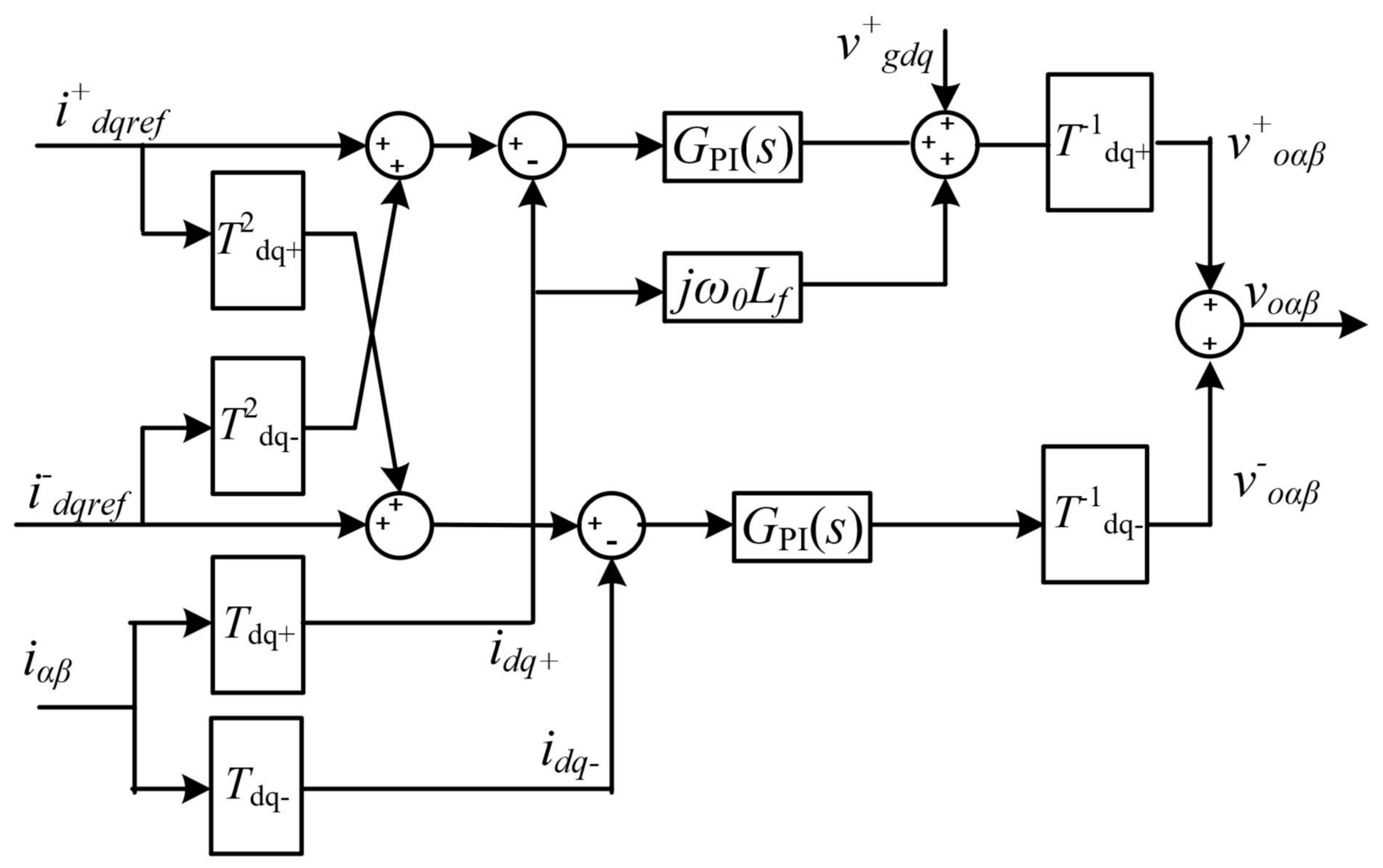
To realize a harmonic control strategy with low computational burden, harmonic control is implemented in the rotating dq reference frame in this paper. After the fundamental positive-sequence dq transformation, the 5th-order negative-sequence harmonic and the 7th-order positive-sequence harmonic are both converted into 6th-order harmonic components. Similarly, the 11th-order negative-sequence harmonic and the 13th-order positive-sequence harmonic are both converted into 12th-order harmonic components. Therefore, the 5th negative-sequence and 7th positive-sequence harmonics can be regulated using a unified 6th-order harmonic controller, while the 11th negative-sequence and 13th positive-sequence harmonics can be regulated using a unified 12th-order harmonic controller, thereby reducing the number of required controllers.
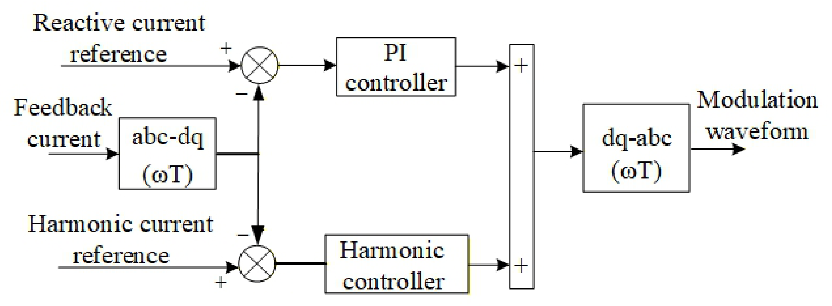
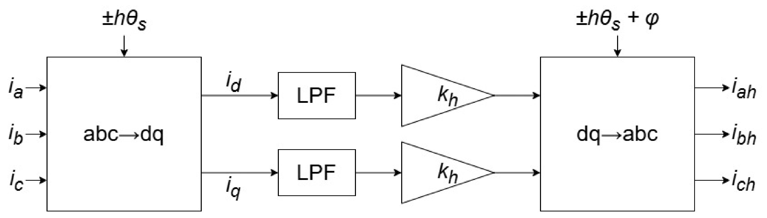
The designed control strategy is illustrated in
Figure 9. After separating the fundamental current reference and the harmonic current reference, they are controlled independently. On the basis of the fundamental steady-state control function, a harmonic current control function is superimposed. These two control loops operate without mutual interference, which improves the flexibility and scalability of the overall control strategy.
Specific harmonic compensation is commonly implemented using resonant controllers [
15], which can generally be classified into two types: the conventional resonant controller and the vector resonant controller [
16]. Compared with the conventional resonant controller, the vector resonant controller can provide higher gain at the specified resonant frequency, enabling more accurate compensation of specific harmonic components. In addition, the bandwidth can be flexibly adjusted by tuning the controller parameters.
To accommodate possible grid frequency deviations,
is introduced into the transfer function of the vector resonant controller, resulting in a quasi-vector resonant controller. Its transfer function is expressed as:
In Equation (
9),
denotes the proportional gain,
denotes the resonant gain, and
represents the fundamental angular frequency.
During parameter design, the differential term of the controller satisfies
of the controlled plant [
16]. Therefore, this paper focuses on the analysis of the parameters
and
, while the parameter
is not further discussed.
The influence of
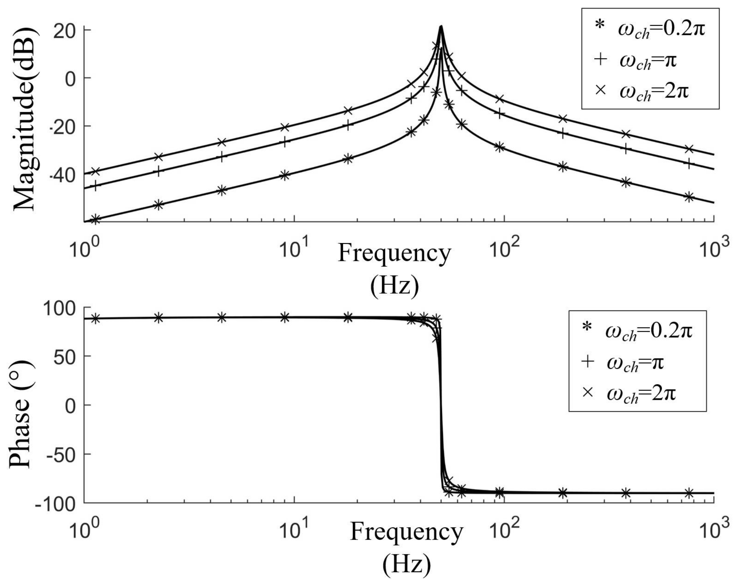
on the frequency characteristics of the controller is illustrated in
Figure 10. It can be observed that
does not affect the gain at the resonant frequency in the amplitude–frequency characteristic, but it does affect the bandwidth. As
increases, the bandwidth becomes larger, and the gain on both sides of the resonant frequency (especially on the right side) increases, resulting in poorer frequency selectivity of the controller. Moreover,
also influences the phase–frequency characteristics near the resonant frequency. A larger
results in a greater phase shift around the resonant frequency.
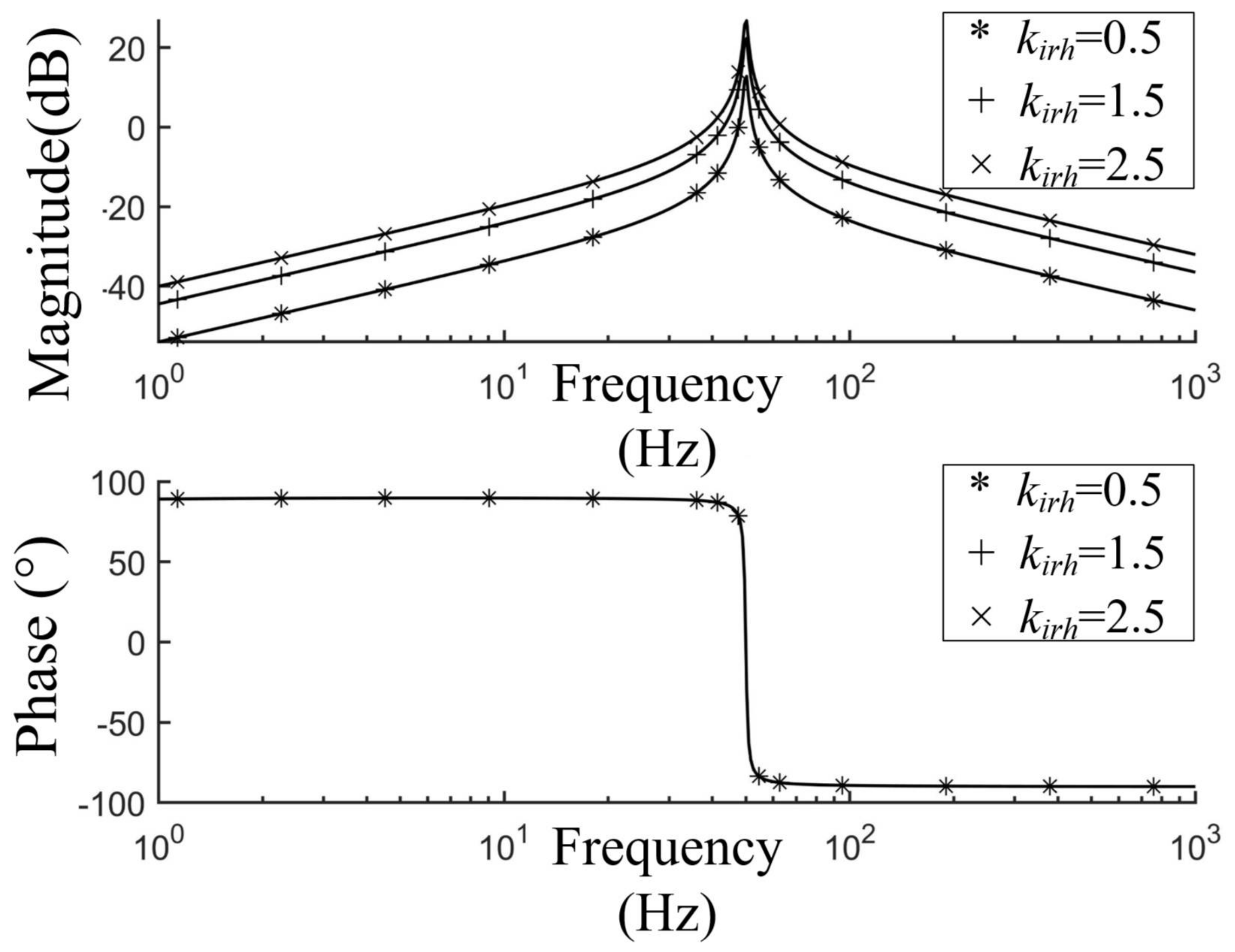
The influence of
on the frequency characteristics of the controller is illustrated in
Figure 11. It can be observed that as
increases, the gain increases not only at the resonant frequency but also on both sides of the resonant frequency, resulting in poorer frequency selectivity. In addition,
does not affect the phase–frequency characteristics.
From the above analysis, the vector resonant controller exhibits a band-pass characteristic. By selecting appropriate parameters, the controller can provide sufficient gain only at the resonant frequency while maintaining zero phase shift after the resonant frequency point, thus avoiding phase lag. Consequently, selective control of specific frequency components can be achieved, making the controller suitable for systems with inherent control delay.
Based on the above frequency-domain analysis, the quasi-vector resonant controller is tuned as follows. (i) Select the resonant bandwidth
: a smaller
improves frequency selectivity but weakens tolerance to grid-frequency drift, whereas a larger
enhances dynamic rejection at the expense of selectivity. In this work,
is chosen to balance selectivity against the typical grid-frequency deviation, and for the
h-th harmonic the resonant bandwidth scales as
. (ii) Choose the resonant gain
to realize a target resonant-peak gain (10 dB in this paper) that ensures steady-state tracking accuracy without compromising selectivity. (iii) Determine the proportional gain from the plant constraint
. This three-step procedure can be formulated as a multi-objective optimization that jointly considers tracking accuracy, selectivity, and robustness [
10].
In the dq rotating reference frame, the resonant term introduces a pair of complex-conjugate poles located at with damping coefficient . Provided that the current-loop crossover frequency lies below , the resonant poles are situated well above the loop crossover; because the band-pass characteristic exhibits zero phase shift away from its narrow resonant band (as shown above), it introduces negligible additional phase lag near crossover, so the phase margin of the original current loop is essentially preserved. Together with the plant-matched proportional gain in step (iii), the chosen and thus endow the current loop with robustness against variations in the plant parameters L and R.