Article

Design, Prototyping, and Integration of Battery Modules for Electric Vehicles and Energy Storage Systems

1
Department of Automotive Engineering, Clemson University, Greenville, SC 29607, USA
2
Holcombe Department of Electrical and Computer Engineering, Clemson University, Clemson, SC 29634, USA
*
Authors to whom correspondence should be addressed.
Electricity 2025, 6(4), 63; https://doi.org/10.3390/electricity6040063
Submission received: 1 August 2025 / Revised: 29 September 2025 / Accepted: 22 October 2025 / Published: 4 November 2025

Abstract

The design of battery modules for Electric Vehicles (EVs) and stationary Energy Storage Systems (ESSs) plays a pivotal role in advancing sustainable energy technologies. This paper presents a comprehensive overview of the critical considerations in battery module design, including system requirements, cell selection, mechanical integration, thermal management, and safety components such as the Battery Disconnect Unit (BDU) and Battery Management System (BMS). We discuss the distinct demands of EV and ESS applications, highlighting trade-offs in cell chemistry, form factor, and architectural configurations to optimize performance, safety, and cost. Integrating advanced cooling strategies and robust electrical connections ensures thermal stability and operational reliability. Additionally, the paper describes a prototype battery module, a BDU, and the hardware and software architectures of a prototype BMS designed for a Hardware/Model-in-the-Loop framework for the real-time monitoring, protection, and control of battery packs. This work aims to provide a detailed framework and practical insights to support the development of high-performance, safe, and scalable battery systems essential for transportation electrification and grid energy storage.

1. Introduction

Electric Vehicle (EV) and Energy Storage System (ESS) batteries are critical components in the transition to sustainable energy, enabling efficient energy storage and delivery for transportation and grid applications [1]. These batteries must deliver high energy density, long cycle life, robust safety, and cost-effectiveness to meet the demands of modern electrification [2]. Central to their performance is the design of battery modules, which consist of multiple individual battery cells arranged in specific series and parallel configurations to achieve the required voltage, capacity, and power [3].
The design process for Electric Vehicle (EV) and Energy Storage System (ESS) battery systems is complex, shaped by evolving standards, application-specific requirements, and distinct performance metrics [4]. Guidelines from the United States Advanced Battery Consortium (USABC) and standards such as IEC 62933 [5], UN 38.3 [6], ISO 26262 [7], and UL 2580 [8] establish performance and safety benchmarks that guide battery module development [9]. For EVs, key design considerations include high gravimetric energy density, fast charging capability, long calendar life, and operation within defined voltage and temperature ranges [10]. ESS designs, in contrast, prioritize energy throughput, long-duration discharge (typically 2–4 h), high system efficiency, and modular scalability [11,12,13]. Grid-connected ESS must also meet standards like UL 9540A and support robust communication protocols and cybersecurity features, including Modbus and IEC 61850 [4,14]. These distinct requirements lead to different trade-offs in battery architecture and system integration. Table 1 summarizes key design metrics for EV and ESS battery systems.
Although the use cases differ, the overall battery design methodology is similar: starting from system-level specifications, this is followed by cell selection, thermal, electrical, and mechanical configuration, then validated through standards-compliant prototyping. Computer-aided design (CAD) tools and Multiphysics simulation tools facilitate optimizing thermal and electrochemical behavior, ensuring safety and reliability under dynamic conditions, etc. Economic factors—including cost per kWh and levelized cost of storage (LCOS)—are integrated early to ensure commercial feasibility. Figure 1 illustrates the overall iterative design process.
Thermal management is vital, as temperature significantly impacts battery efficiency, lifespan, and safety. Cooling strategies range from air cooling and liquid channels to phase change materials, all designed to maintain safe operating temperatures and mitigate thermal runaway risks. Rigid and robust electrical connections using low-resistance busbars and bonding wires minimize power losses and enhance mechanical stability. Safety features such as high-voltage isolation, venting systems, and protection circuitry are fundamental to EV and ESS systems.
Numerous studies have explored the design of lithium-ion batteries in modules or Battery Management Systems (BMSs) for various applications. For instance, Andrea et al. [18] provide an in-depth discussion on module design, sensing, and switching; however, it lacks a focus on key design metrics critical for EV and ESS applications. While much of the existing research centers on specific aspects of battery design, there is limited work addressing a holistic approach to battery pack design. For example, Divakaran et al. [19] present a modular hexagonal battery design using six 18650 cells, emphasizing liquid cooling. However, it does not consider scalability and integration of the cooling system into larger battery packs. Similarly, Astaneh et al. [20] utilize a two-stage optimization framework for battery pack design but oversimplify the cooling system dynamics and neglect the critical role of electrical interconnections. Additionally, Pierri et al. [21] propose an advanced battery design method for EV applications, focusing on the trade-off between the battery pack capacity and weight. However, it overlooks the integration of the Battery Disconnect Unit (BDU) and BMS into the overall system, which is crucial for ensuring safe and efficient operation under varying environmental and operating conditions. Reference [22] explores the optimal sizing of lithium-ion battery packs for mobile microgrid applications, primarily focusing on the physical layout and sizing required for mobility. However, it lacks in-depth design considerations for the battery pack and its associated components.
Likewise, reference [23] discusses various thermal management techniques for EV battery packs but lacks integration of these techniques and their interdependencies with other subsystems. Furthermore, in [24], the authors focus on physical integration and protection of the battery pack but overlook critical aspects of a holistic battery system design, such as the integration of the BMS and BDU. It also neglects thermal management, modularization, scalability and communication aspects.
The absence of a comprehensive design approach that includes all critical elements—battery modules, cooling systems, BDU, and BMS—limits the potential for real-world application in highly integrated EV and ESS systems. This paper explores the critical factors in battery module design for EV and ESS applications, emphasizing challenges and strategies to ensure high performance, safety, and reliability. It highlights practical aspects of design, integration, and communication. The primary scope of this work is conventional lithium-ion battery technology, which remains the predominant chemistry in commercial EV and ESS deployments today. While we recognize the importance of emerging chemistries (e.g., solid-state and lithium-metal), sustainability aspects such as recyclability and second-life use, as well as digitalization trends including digital twins, predictive diagnostics, and cybersecurity, are beyond the scope of this study. Instead, the focus is on delivering actionable guidance for current-generation systems through the design, prototyping, and integration of modules, BDUs, and BMS, demonstrated with real prototypes. The key contributions of this paper are as follows:
  • It presents a comprehensive design framework for modular architecture for EV/ESS battery systems.
  • It demonstrates the application of the Design Failure Mode Effect Analysis (DFMEA) concept to identify and mitigate potential design-level failure modes to enhance safety and reliability.
  • It presents prototype development of battery modules, BDU and BMS hardware/software with functional verification of some of the components.
  • It provides practical, implementation-focused guidance for conventional lithium-ion battery system.
The rest of the paper is organized as follows: Section 2 covers battery architecture and design, focusing on cell selection, mechanical integration, and thermal management. Section 3 discusses the BDU, a crucial component for battery switching and protection, often overlooked in existing studies. Section 4 describes the BMS hardware and software architecture. Section 5 presents prototypes of the module, BDU, and BMS developed by our team, designed for integration into a real commercial vehicle, followed by a conclusion.

2. Battery Architecture and Design

In EVs, two primary architectures are employed: (i) cell-to-module-to-pack and (ii) cell-to-pack. While the traditional approach has been cell-to-module-to-pack, there is a growing trend toward cell-to-pack configurations for EV applications due to their potential energy density and cost advantages. However, a modular architecture remains critical in ESS to ensure scalability and flexibility. The number of cells in series ( N s ) is determined by the voltage requirements of the module or pack, and the number of parallel cells ( N p ) is determined by the energy (in kWh) and power/current demands. In modular configurations, module voltage is typically limited to 60 V to retain classification as a low-voltage system, simplifying the safety requirements. This constrains the number of series-connected cells in a module.

2.1. Cell Selection

Cell selection is a critical design step in battery systems for EV and ESS, as it directly influences system-level metrics such as energy density, power capability, thermal behavior, safety, and cost. The form factor and chemistry must align with application-specific requirements, including power profile, packaging constraints, and lifetime targets. For EV applications, cells must support high discharge C-rates, fast charging, and long calendar life under wide thermal cycling, in addition to offering high gravimetric and volumetric energy densities. This necessitates cells with low internal impedance and robust thermal characteristics to manage high C-rates. Conversely, ESS applications prioritize cycle life (5000+ cycles), thermal stability, and cost per kWh over energy density, often operating at lower C-rates (0.5C–1C) with longer-duration charge/discharge cycles [4,13].
Three primary commercial cell formats dominate the market: cylindrical, pouch, and prismatic. Each format presents trade-offs between energy density, manufacturability, thermal behavior, and mechanical integrity [25]. Table 2 compares these cell types. Cylindrical cells (e.g., 18,650, 21,700, and 4680) offer superior mechanical robustness and thermal uniformity. They are widely adopted in EVs (e.g., Tesla Model Y uses 21,700 cells) due to scalable automated production and high power density. Although their packaging efficiency is lower due to interstitial gaps, they offer high flexibility in pack/module design [26]. Prismatic cells, common in EVs and ESS, provide high packing density and ease of module integration but may exhibit swelling and uneven heat distribution. They are preferred in ESS rack systems and EVs with space-constrained, shape-optimized battery trays [27]. Pouch cells offer the highest flexibility in packaging and energy density per unit volume but are mechanically less robust and prone to swelling, and thus require more complex enclosure designs for protection. These are used in some EVs and high-density ESS deployments where thermal management is tightly controlled [28].
Cell characterization through experimental techniques—including Electrochemical Impedance Spectroscopy (EIS), capacity fade testing, and thermal characterization—is essential before integration. Accurate cell models are derived from this data and used in system simulations to optimize pack-level design and BMS algorithms [29]. As battery technologies evolve, silicon-dominant anodes, solid-state electrolytes, and lithium-metal designs have garnered attention for next-generation applications. However, current commercial deployments still predominantly rely on mature lithium-ion chemistries such as NMC, LFP, and NCA, with cell format decisions strongly driven by application-specific trade-offs in safety, performance, and manufacturability [30], and in some cases, design constraints and existing product line-ups.

2.2. Mechanical Integration

Mechanical integration varies significantly with cell selection and heavily influences module durability under automotive vibration. Cylindrical cells, lacking plastic insulation, require appropriate spacing to avoid shorting and are usually spot-welded or wire-bonded to nickel or copper busbars. Prismatic cells, encased in rigid housings, allow high stacking density and are typically interlinked via ultrasonic or laser welding. Compression pads or cushioning layers manage cell swelling and mechanical tolerances. Pouch cells are clamped and compressed to suppress swelling during charge and discharge cycles. Rigid busbars or flexible wires connect the module’s terminals to adjacent modules. Adhesives are applied between cells and the structural members to absorb micro-vibrations, improve structural stability, and prevent cell movement during thermal cycling and mechanical shock [31]. For EV batteries, adhesives that enable easy disassembly are recommended to facilitate safe cell extraction for second-life applications.

2.3. Thermal Management

Robust thermal control ensures lithium-ion battery safety, cycle life, and performance uniformity. Prismatic cells benefit from flat surface cooling using cold plates, which circulate coolant. Vulnerable to edge heating and dimensional instability, pouch cells typically use side-cooled plates combined with thermally conductive gap fillers. Cylindrical cells are cooled using base plates, similar to prismatic cells. Serpentine cooling channels that conform to the gap between the cells are also widely used, as they offer superior heat transfer. Thermal Interface Materials are widely used on the contact surfaces to increase heat transfer. phase change materials (PCMs), embedded in interstitial gaps to improve heat rejection, and hybrid approaches combining PCM with cold plates or serpentine channels can reduce thermal peaks by over 30% during high C-rate cycling [32]. However, not enough applications use the hybrid approach due to associated difficulties and higher failure risk. Negative Temperature Coefficient (NTC) thermistors are distributed across modules to monitor real-time temperature at critical nodes, supporting active thermal management and fault detection.

3. Battery Disconnect Unit (BDU)

A BDU is an important high-voltage (HV) battery system (HVBS) component. The primary function is to safely connect and disconnect the HVBS from the rest of the electrical system. It includes the following major components:
  • HV contactors/breaker: These electromechanical switches open/close the battery terminals. There are usually two main contactors (high power) and a precharge contactor to charge the circuit capacitance safely. EV battery packs may include another set of high-power contactors for Direct Current (DC) fast charging (DCFC).
  • Precharge resistor: The precharge resistor limits the inrush current during initial connection by slowly charging the downstream capacitance before switching the main HV contactor.
  • HV Fuses: HV fuses provide overcurrent protection. There can be multiple fuses within the BDU.
  • Busbars: These connect the battery terminals to the contactors and the power distribution terminals.
  • Current Sensor: These measure the current flowing in/out of the battery. For failsafe design, redundant measurement using a shunt-type and a Hall-effect current sensor is common.
  • Temperature Sensor: These measure the temperature at the busbars and precharge resistor.
  • Low Voltage (LV) connectors: These include control cables for contactor control, temperature sensors, diagnostics, and status feedback, and connect to the BMS.
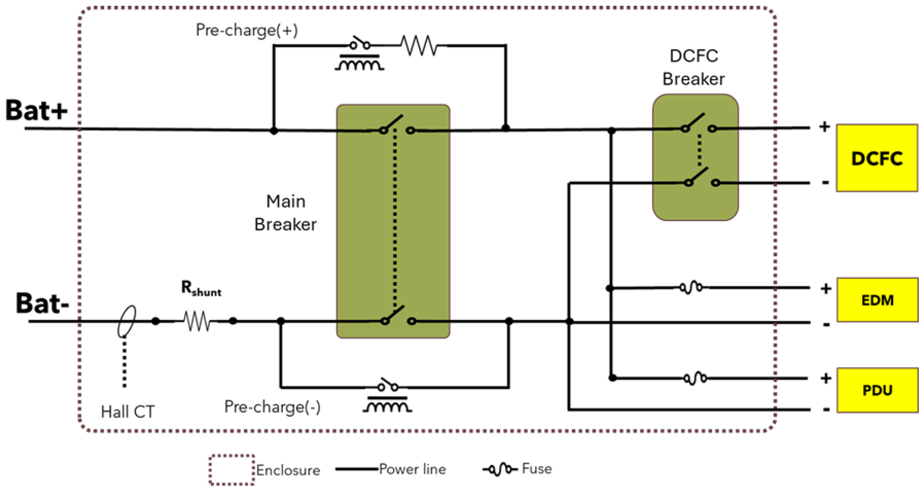
Figure 2 shows an example schematic of a BDU for an EV battery pack application as evident from a DCFC connection. The BDU uses two breakers instead of four conventional contactors, and connects to the Power Distribution Unit (PDU) and the vehicle’s Electric Drive Module (EDM). A precharge on the negative line is required as the two poles open/close simultaneously. Components such as contactors and fuses are selected based on the voltage and current requirements. In case of the precharge resistor, the downstream circuit capacitance and the time required to charge this circuit capacitance to 95% of the battery voltage are of critical importance. As a rule of thumb, the resistance is approximated by Equation (1) [33]:
3 × R C = T max
Peak power = V b a t 2 R
Energy dissipation = 1 2 C V b a t 2
where R is the resistance, C is the aggregate downstream circuit capacitance, and T max is the maximum permissible time required to charge the capacitance. In addition, important factors in selecting a precharge resistor include the peak power (Equation (2)), energy dissipation in the resistor (Equation (3)), average power over the T max duration, and the tolerance over the operating voltage range.

4. Battery Management System (BMS)

A BMS is an electronic system consisting of hardware and software that manages the operation of the battery. Primary functions include the following:
  • Monitoring voltage, current and temperature of cells or module in the battery pack;
  • Protection by preventing over-charging, over-discharging, over-current and over-heating;
  • Estimation of states such as state of charge (SOC), State of Health (SOH), State of Power (SOP), etc.;
  • Thermal management by coordinating with the cooling/heating system;
  • Balancing by equalizing charge across cells to extend battery life and maintain performance;
  • Communicating to the rest of the system (to the vehicle system using, for example, Controller Area Network (CAN) or Local Interconnect Network (LIN) protocols, or to the Energy Management System (EMS) using the Distributed Network Protocol 3 (DNP3), IEC 61850, Modbus protocols).

4.1. Hardware Architecture

BMS comprises several key components: sensors for measurement, a microprocessor for acquiring and processing these measurements, circuitry to perform essential functions, and interfaces for communication and actuation. Each module within the battery pack may include a dedicated cell sensing circuit (CSC) or share one with adjacent modules. These CSCs are commonly designed for daisy-chain connectivity, facilitating streamlined communication. The isolated Serial Peripheral Interface (isoSPI) is often employed due to its high bandwidth, enhanced Electro-Magnetic Interference (EMI) immunity, and support for redundancy when configured in a closed-loop ring topology. CSCs typically support passive cell balancing by dissipating excess energy from cells with a higher state of charge. A pack monitor measures the overall pack voltage and current and may be integrated into the main microprocessor or implemented as an independent circuit.
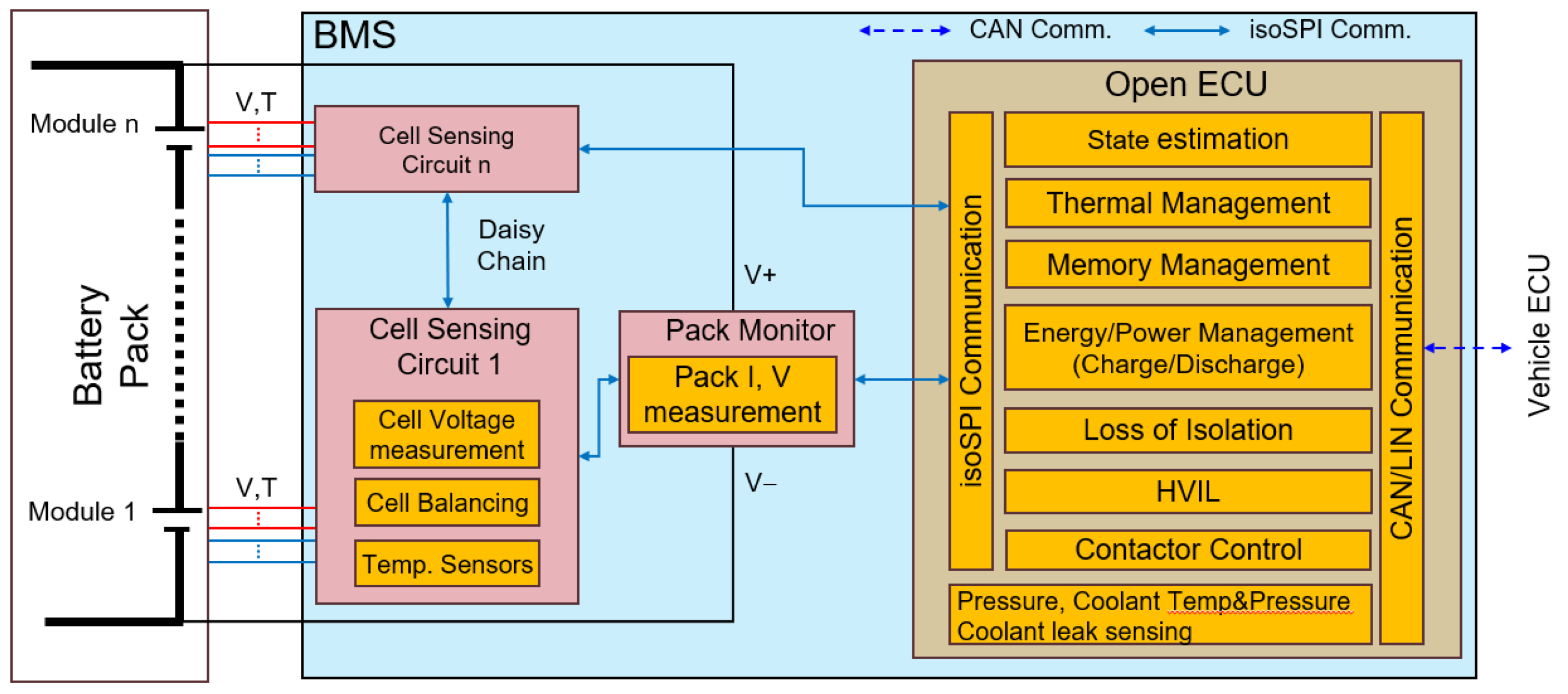
Figure 3 illustrates a typical hardware architecture of a BMS in an EV. On the right, a battery pack comprising n modules is depicted. Each module is connected to an ADBMS6830 CSC, which measures individual cell voltages (up to 16 series-connected cells) and temperature. Multiple CSCs are interconnected via an isoSPI daisy chain; optionally, the chain can be closed for higher communication bandwidth and redundancy. The pack monitor, implemented using an ADBMS2950, measures the total voltage and current of the battery pack. The main controller, OpenECU M450, together with the CAN/LIN gateway (OpenECU M130), manages core BMS functions and communicates with both the pack monitor and CSCs via isoSPI, while interfacing with the rest of the vehicle through a CAN/LIN bus.

4.2. Software Architecture

The BMS software is developed using a model-based design (MBD) methodology, with MATLAB 2024a and Simulink as the standard primary platforms for algorithm development, simulation, and code generation [34]. foxBMS [35], an open-source platform, is another widely used development tool for BMS software. The MBD method facilitates traceability, rapid prototyping, and seamless integration of control and diagnostic algorithms. Figure 4 provides a high-level overview of the BMS software architecture, highlighting the data flow between measurement modules, estimation algorithms, protection functions, and actuator control blocks. This architecture is further developed in the Matlab/Simulink platform in the case study presented in Section 5. OpenECU blocksets in Simulink provide low-level hardware abstraction for the target hardware (OpenECU hardware), enabling the efficient implementation of features such as CAN communication, analog and digital input/output (I/O), and Pulse Width Modulation (PWM)-based control [36].
Sensor data from the CSCs and the pack monitor is processed in real time to derive various battery state parameters. Key measurements include cell and module voltage, current, temperature, pack pressure, and coolant leak detection. These inputs form the basis for decision-making in safety-critical and energy optimization routines [37].
The software generates control signals for several key actuators. These include breaker/contactor drivers, cell balancing, and HV Interlock Loop (HVIL) PWM signaling. The actuator logic is tightly integrated with the system’s diagnostics and fault handling mechanisms to ensure safe operation under all conditions [38]. The final code is generated using the Wind River Diab Compiler [39], which produces optimized flashable binaries that are deployed to OpenECU M450 and OpenECU M130 controllers.
All software components are divided into logical subsystems to ensure clarity, maintainability, and functional safety compliance stipulated in ISO 26262 goals for functional safety [7]. The modularity of the architecture also allows for future scalability and integration with additional features as and when required.

4.3. Cost Analysis and Scalability

The cost of a battery module can be broadly divided into two categories: (a) cell cost and (b) non-cell system cost. Cell cost is typically the dominant factor and depends on parameters such as chemistry, form factor (cylindrical, pouch, or prismatic), and procurement volume. Large-scale production significantly reduces the cost per kilowatt-hour, whereas prototype or low-volume production leads to substantially higher unit costs. Non-cell costs include the mechanical structure of the module, thermal management components, cell sensing circuits, busbars, and related hardware. At the pack level, additional elements such as the BMS, busbars, and Battery Disconnect Units contribute significantly. These costs are also highly sensitive to production scale; in high-volume manufacturing, they differ markedly from those in prototype or low-volume builds. Non-cell costs further encompass labor, quality assurance, and non-recurring engineering expenses for tooling and certification. While some expenditures are distributed at the pack level, module-level design choices directly influence the overall cost. This discussion is presented qualitatively rather than quantitatively, as costs are strongly dependent on chemistry, supply chain conditions, and production scale.
With respect to scalability, modules can be flexibly connected in series or parallel to configure a larger system based on EV pack or ESS requirements. While EV packs are generally limited to a few hundred kilowatt-hours, Energy Storage Systems can extend to the multi-megawatt-hour scale. The modular design therefore enables adaptation across applications, although architecture and integration choices influence cost efficiency at different scales.

5. Case Study of Design and Prototyping

This section presents the design and development of a prototype battery module, a BDU and a BMS, intended for an EV application. The minimum specifications required to initiate the battery pack design are summarized in Table 3. As with any engineering design, several constraints/assumptions are considered, including (a) the use of INR-21700-50G cylindrical cells, and (b) restrictions against modifying the battery pack enclosure. For context, our research group previously conducted a detailed characterization of the INR-21700-50G cell (nominal capacity: 4900 mAh) [40] and evaluated its suitability for automotive applications [41]. In the following we discuss different aspects of the prototype development. At every stage, we applied the industry-standard DFMEA process to identify potential failure modes in the design, evaluate their impact on the system, and define strategies to mitigate those effects and ensure the safety and reliability of the system.

5.1. Cell Configuration and Module Design

Based on the mechanical constraints of the battery tray and the layout of modules within the enclosure, the pack is designed to consist of eight identical modules connected in series to meet the voltage and power requirements. Using Equation (4) and assuming an individual cell voltage range of 2.8–4.15 V, the permissible number of cells in series is calculated to lie within 90 N s 101 . A value of N s = 96 is selected to maintain modular symmetry.
Subsequently, the number of cells connected in parallel ( N p ) is determined using Equation (5). Considering a cell voltage of 3.4 V at 20% SOC and a maximum continuous discharge rate of 3C (corresponding to 15 A per cell), the resulting parallel requirement is N p 36 . Hence, a final configuration of 36P96S is adopted. This results in a total pack energy of approximately 62 kWh with 3456 cells, satisfying the design target for installed energy. The sizing process involves iterative adjustments to balance mechanical layout, electrical performance, and thermal management constraints.
Given the 96 cells in series and eight modules, each module is designed with a 36P12S configuration:
Min . Operating Voltage Min . Cell Voltage N s Max . Operating Voltage Max . Cell Voltage
Max . Charge / Discharge Power N s × Cell Voltage × Cell Current Limit N p
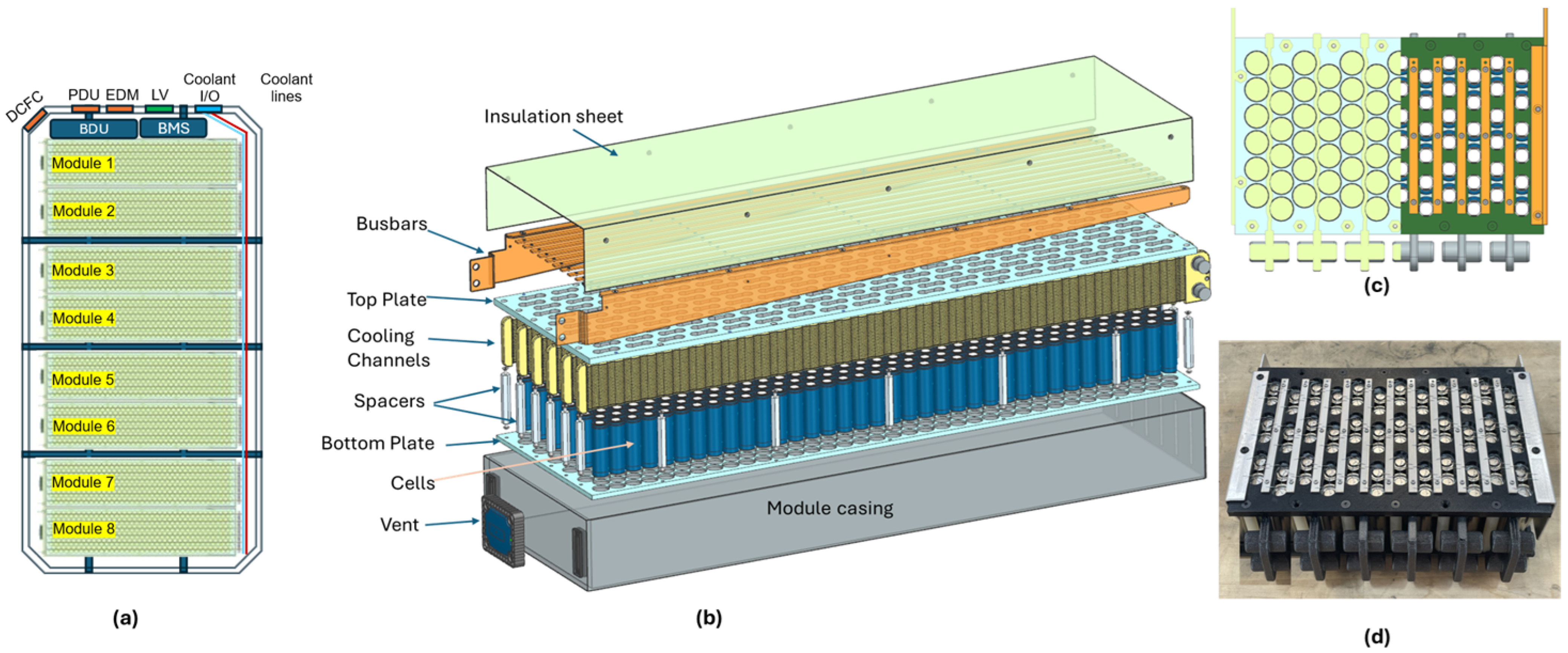
Figure 5a shows the CAD model of the battery pack depicting the eight battery modules, BDU and BMS. The module’s HV terminals are on the left, and the coolant hoses are on the right. Figure 5b shows the CAD model of a module which houses 432 Samsung INR21700 cells arranged in a 36P12S configuration. The cells are arranged in a hexagonal tessellated pattern, optimizing space utilization within the module. Each row constitutes one parallel block. The cells are sandwiched between a top and bottom plate made of insulating material. The top plate features slots to provide access to each cell’s positive and negative terminal for wire bonding and to support venting during thermal runaway events.
Nickel-plated copper busbars are mounted onto the top plate, with each cell terminal connected to the busbars via 400 µm thick aluminum wire ultrasonically bonded to the cell terminals and the busbars. This robust bonding ensures reliable electrical connections capable of withstanding mechanical stresses and vibrations. The bonding wire thickness is chosen so that it fuses when the current is near the cell’s safety limit, preventing the escalation to thermal runaway. Spacers secure the top and bottom plates, providing mechanical stability.
For thermal management, U-type serpentine cooling channels [42] are incorporated between every two rows of cells. Thermal Interface Material (TIM) ensures optimal surface contact between the cooling channel and the cell surfaces, enhancing heat transfer efficiency. In addition, its adhesive property holds the cell to the cooling channel during assembly. The coolant flows through the lower half of each channel, reaches the far end, and then returns through the upper half before exiting the module. All cooling channels are arranged in parallel to ensure uniform coolant flow and minimize pressure head loss, which can be significant if the channels are connected in series. The U-type coolant flow contributes to efficient thermal control, ensuring that each cell is adequately cooled under varying operational conditions, thereby minimizing the temperature gradient across the module.
An insulating sheet is applied over the live busbars for HV isolation to prevent accidental short circuits. The entire assembly is enclosed in a metallic casing, which includes a vent to expel gases and to avoid pressure buildup during a thermal runaway event.
Figure 5c shows the CAD model for the prototype (one-sixth size) with 6P12S cell configuration. The left half shows the sectional (Z-axis) view illustrating the serpentine cooling channels along the length. Figure 5d shows the assembled prototype. The module casing and insulation sheet are hidden to show the busbars and the wire bonding.
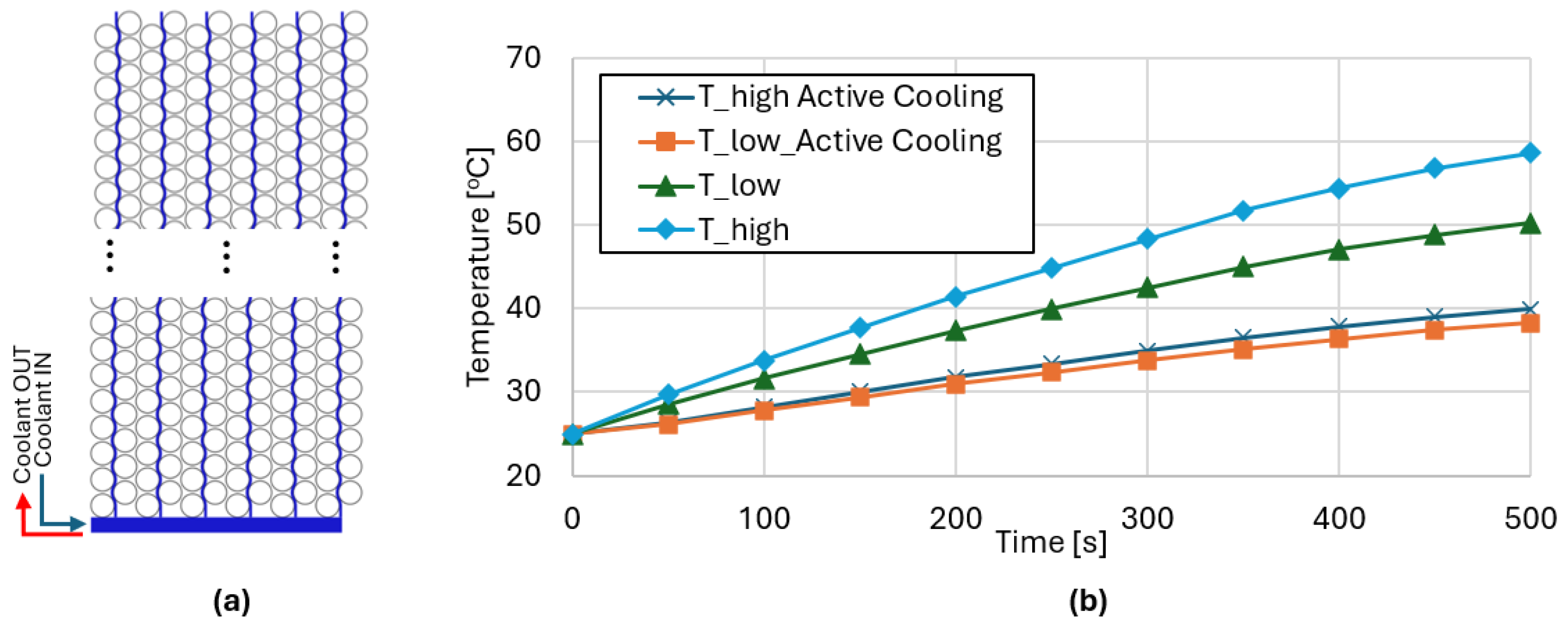
Figure 6a illustrates the thermal simulation setup, where the U-type serpentine cooling channels are highlighted in blue. A representative result for a DCFC scenario is shown in Figure 6b, comparing cases with active cooling enabled and disabled. For the active cooling case, a coolant flow rate of 20 L/min of ethylene glycol was assumed, with both ambient and coolant inlet temperatures set at 25 ° C . The charging current was 360 A, corresponding to a 2C rate. The results show the temperature evolution within the module, highlighting the maximum and minimum cell temperatures. Without active cooling, the module temperature rises significantly and exhibits a large gradient between the hottest and coolest cells. In contrast, active cooling limits the maximum temperature to approximately 40 ° C , while maintaining the intra-module temperature gradient within 2 ° C .

5.2. BDU Design

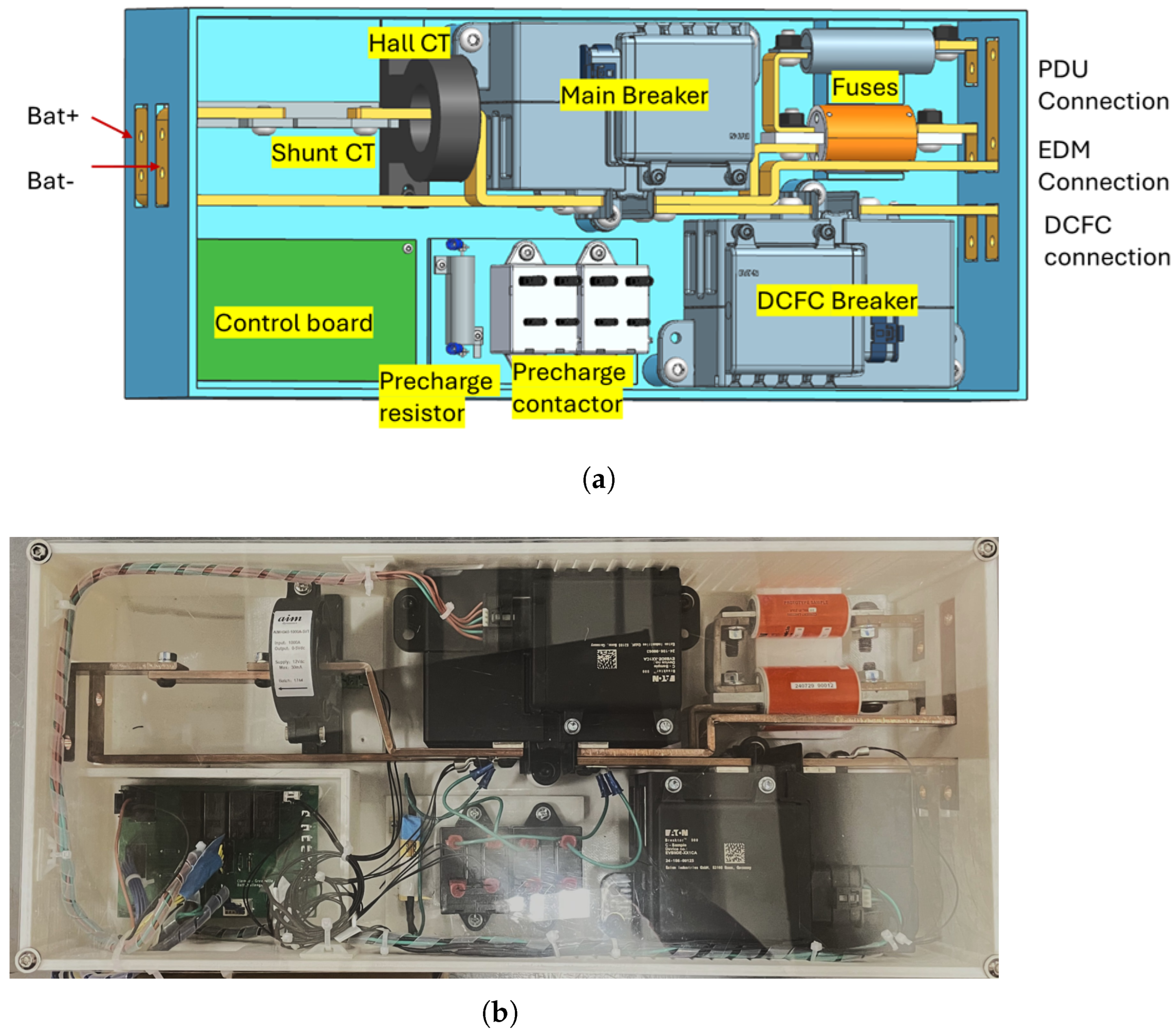
The CAD model of the BDU and the assembled prototype is shown in Figure 7. This design is based on the HV schematic in Figure 2. Two Eaton Breaktors® [43] replace the main breaker and the DCFC breaker. The enclosure is made of insulating materials such as PC-ABS. The battery terminals are on the left side, while the PDU, EDM, and DCFC terminals are on the right. Busbars are used internally for HV connections, ensuring low resistance and mechanical rigidity. The creepage and clearance distances from the HV components are designed to meet the specified requirements. A shunt current transducer and a Hall-effect current transducer provide redundant current measurement. Additionally, five temperature sensors affixed to the Breaktor terminals (two per Breaktor) and precharge resistor give temperature feedback to the BMS.
The precharge resistance is calculated based on the assumptions that the target voltage at the end of precharge is greater than 95% of the battery terminal voltage within 100 ms and the downstream circuit capacitance of 1250 μ F, which is within a ballpark estimate for an EV application.

5.3. BMS Design

Figure 8 illustrates the development board used for rapid prototyping of BMS software. It serves as a Hardware-in-the-Loop/Model-in-the-Loop (HIL/MIL) framework for BMS software development. The primary controller, OpenECU M450, interfaces with a host PC on the right via a Kvaser CAN adapter, enabling firmware flashing, real-time calibration, and interaction with the BMS application software. All physical pins of the M450 are routed to board-mounted connectors, allowing flexible pin assignments during prototyping. A module emulator capable of simulating 16 series-connected cells (ADI DC2472A) is connected to an ADBMS6830 CSC, which communicates with the M450 via isoSPI.
On the left, the BDU prototype is connected to the digital I/O connectors, establishing direct communication with the M450’s I/O lines. Additionally, a combination pressure and temperature sensor (used for coolant inlet/outlet monitoring) and an Amphenol coolant leakage sensor are integrated into the setup. These sensors generate analog signals corresponding to pressure and temperature, which are routed to the M450’s analog input channels for monitoring and diagnostic purposes. MIL simulations are employed for functions that cannot be replicated in hardware during the development phase.
Figure 9 presents two screenshots of MATLAB Simulink: the top-level BMS software architecture and the Controls subsystem that illustrates specific BMS functionalities. The model is compiled using the WindRiver Diab compiler to generate machine code for the OpenECU M450. The resulting binary is flashed onto the target using the OpenECU Calibrator tool.
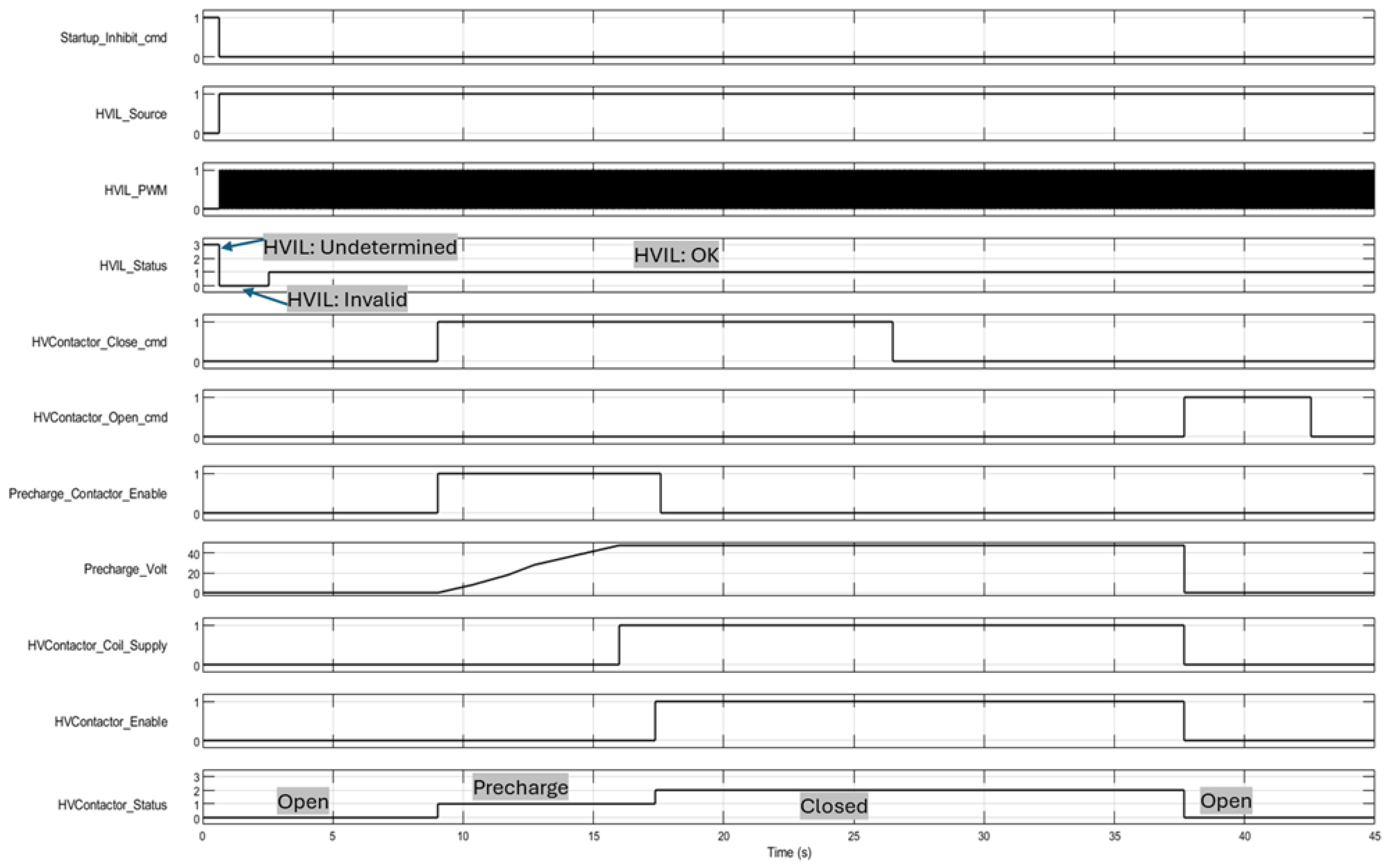
Figure 10 illustrates the integrated operation of the BMS and BDU, highlighting the HVIL initialization and the operation of the main contactors. Once the Startup-Inhibit-cmd flag is cleared, the BMS generates a PWM signal to initiate the HVIL check. This causes the HVIL-Status to transition from Undetermined to Invalid. The signal passes through all safety interlocks and is looped back to the BMS (if the return signal is not detected, a fault is assumed). When the signal is successfully received back at the BMS, the HVIL-Status updates from Invalid to OK.
Upon successful HVIL validation, the BMS issues the HVContactor-Close-cmd command, switching the precharge contactors on. The precharge voltage begins to increase toward the source voltage of 50 V. Since the switching threshold is 95% (that is, 47.5 V), the transition occurs quickly, within approximately 100 ms. However, the figure depicts the voltage rising gradually for illustrative purposes. Once the precharge voltage reaches the threshold, the BMS enables the 12 V coil supply by enabling HVContactor-Coil-Supply followed by HVContactor-Enable, closing the main contactors. During this sequence, the HVContactor-Status transitions from Open to Precharge, and finally to Closed. At this point, the precharge contactors are turned off, as the main contactors are now engaged.
Later, when the BMS receives a HVContactor-Open-cmd command, it deactivates the HVContactor-Enable signal, cutting the contactor coil supply voltage and causing the contactors to open. The result is reflected by the HVContactor-Status transitioning from Closed back to Open.

6. Conclusions

This paper presented a comprehensive overview of a high-voltage battery system’s design, integration, and prototyping for EV and stationary ESS applications. Key aspects of system design were explored, including system-level requirements, cell selection, module architecture, mechanical and thermal integration, BDU design, and BMS hardware and software architecture.
The iterative design methodology, guided by industry standards such as USABC, ISO 26262, and UL 2580, enabled a structured approach to achieving safety, performance, and cost objectives. Emphasis was placed on understanding the cell format, mechanical integration, and effective thermal management strategies to ensure operational stability under different operating conditions. The BDU was designed to safely manage high-voltage switching and protection functions, incorporating components such as HV contactors, fuses, and precharge circuits. A modular BMS platform was developed, using model-based design in MATLAB/Simulink and validated using prototype hardware. The system supports advanced state estimation, fault handling, and CAN protocol communication with the vehicle/host PC. The prototype modules and subsystems were fabricated to validate the design assumptions and demonstrate the integration of the system. These efforts form the foundation for further development, including full-scale pack assembly, system-level testing, and certification toward production deployment.
Future work will optimize thermal performance under dynamic load conditions, enhance BMS algorithms for predictive diagnostics, and validate system reliability through environmental and life-cycle testing. We will investigate and compare the characteristics of HVBS at the cell, module, and pack levels. Additionally, we will extend the design methodology to incorporate emerging chemistries, sustainability aspects, and digitalization trends, broadening its applicability beyond conventional lithium-ion systems.

Author Contributions

Conceptualization, S.P. and J.Z.; methodology, S.P. and J.Z.; software, S.P.; validation, S.P. and J.Z.; resources, J.Z. and B.A.; writing—original draft preparation, S.P., V.Y.G.; writing—review and editing, S.P., J.Z., B.A. and R.S.; visualization, S.P., V.Y.G.; supervision, J.Z. and B.A.; funding acquisition, J.Z., R.S. and B.A. All authors have read and agreed to the published version of the manuscript.

Funding

This research was partially supported by the U.S. Department of Energy through the Battery Workforce Challenge Program, managed by Argonne National Laboratory. The authors gratefully acknowledge hardware, software, and logistical support from industry partners, including Stellantis, Samsung SDI America, American Battery Technology Corporation, Battery Innovation Center, Inc., Eaton, AVL, DANA, Inc., Analog Devices, Inc., Hesse Mechatronics, Vibration Research, Vector North America, Siemens, and BorgWarner, Inc.

Data Availability Statement

Data used in this article will be made available by the authors on reasonable request.

Conflicts of Interest

The authors declare no conflicts of interest.

Abbreviations

List of Symbols and abbreviation
Abbr.Full FormAbbr.Full Form
CADComputer-Aided DesignCANController Area Network
CTCurrent TransducerCSCCell Sensing Circuit
DCDirect CurrentDNP3Distributed Network Protocol 3
DCFCDC Fast ChargingEMIElectromagnetic Interference
EMSEnergy Management SystemEISElectrochemical Impedance Spectroscopy
ESSEnergy Storage SystemHVBSHigh Voltage Battery System
HVHigh VoltageHVILHigh Voltage Interlock Loop
I/OInput/OutputIECInternational Electrotechnical Commission
ISOInternational Organization for StandardizationisoSPIIsolated Serial Peripheral Interface
LCOSLevelized Cost of StorageLINLocal Interconnect Network
LFPLithium Iron PhosphateNCANickel Cobalt Aluminum
NMCNickel Manganese CobaltNTCNegative Temperature Coefficient
PCMPhase Change MaterialPDUPower Distribution Unit
PC-ABSPolycarbonate-Acrylonitrile Butadiene StyrenePWMPulse Width Modulation
SCADASupervisory Control and Data AcquisitionSOCState of Charge
SOPState of PowerSOHState of Health
TIMThermal Interface MaterialUNUnited Nations
USABCU.S. Advanced Battery ConsortiumULUnderwriters Laboratories

References

  1. IEA. Global EV Outlook. 2024. Licence: CC BY 4.0. Available online: https://www.iea.org/reports/global-ev-outlook-2024 (accessed on 22 July 2025).
  2. Nyamathulla, S.; Dhanamjayulu, C. A review of battery energy storage systems and advanced battery management system for different applications: Challenges and recommendations. J. Energy Storage 2024, 86, 111179. [Google Scholar] [CrossRef]
  3. Ngoy, K.R.; Lukong, V.T.; Yoro, K.O.; Makambo, J.B.; Chukwuati, N.C.; Ibegbulam, C.; Eterigho-Ikelegbe, O.; Ukoba, K.; Jen, T.C. Lithium-ion batteries and the future of sustainable energy: A comprehensive review. Renew. Sustain. Energy Rev. 2025, 223, 115971. [Google Scholar] [CrossRef]
  4. Farakhor, A.; Wu, D.; Wang, Y.; Fang, H. A Novel Modular, Reconfigurable Battery Energy Storage System: Design, Control, and Experimentation. arXiv 2023, arXiv:2301.05168. [Google Scholar] [CrossRef]
  5. IEC TS 62933-3-1; Electrical Energy Storage (EES) Systems—Part 3-1: Planning and Installation–General Specification. International Electrotechnical Commission: Geneva, Switzerland, 2018.
  6. United Nations. UN Manual of Tests and Criteria: Lithium Metal and Lithium Ion Batteries; United Nations: New York, NY, USA; Geneva, Switzerland, 2019. [Google Scholar]
  7. ISO 26262-4; Road Vehicles–Functional Safety: Part 4: Product Development at the System Level, 2nd ed. International Organization for Standardization: Geneva, Switzerland, 2018.
  8. UL 2580; Batteries for Use in Electric Vehicles. Underwriters Laboratories Inc.: Northbrook, IL, USA, 2020.
  9. USABC. Goals for Advanced High-Performance Batteries for Electric Vehicle (EV) Applications. 2023. Available online: https://uscar.org/download/246/energy-storage-system-goals/12837/goals-for-advanced-high-performance-batteries-for-electric-vehicle-ev-applications.pdf (accessed on 22 July 2025).
  10. Lunz, B.; Yan, Z.; Gerschler, J.B.; Sauer, D.U. Influence of plug-in hybrid electric vehicle charging strategies on charging and battery degradation costs. Energy Policy 2012, 46, 511–519. [Google Scholar] [CrossRef]
  11. IEA. Tracking Clean Energy Progress. 2023. Available online: https://www.iea.org/reports/tracking-clean-energy-progress-2023 (accessed on 22 July 2025).
  12. Lazard. Levelized Cost of Storage Analysis–Version 10.0. 2025. Available online: https://www.lazard.com/media/uounhon4/lazards-lcoeplus-june-2025.pdf (accessed on 22 July 2025).
  13. USCAR. USABC Low-Cost/Fast Charge EV Goals. 2024. Available online: https://uscar.org/download/246/energy-storage-system-goals/12840/low-cost-fast-charge-ev-goals.pdf (accessed on 22 July 2025).
  14. Trevizan, R.D.; Obert, J.; De Angelis, V.; Nguyen, T.A.; Rao, V.S.; Chalamala, B.R. Cyberphysical Security of Grid Battery Energy Storage Systems. IEEE Access 2022, 10, 59675–59722. [Google Scholar] [CrossRef]
  15. UL 9540A; Test Method for Evaluating Thermal Runaway Fire Propagation in Battery Energy Storage Systems. Underwriters Laboratories Inc.: Northbrook, IL, USA, 2019.
  16. ISO 15118; Road Vehicles – Vehicle to Grid Communication Interface. International Organization for Standardization: Geneva, Switzerland, 2019.
  17. IEC 61850; Communication Networks and Systems for Power Utility Automation. International Electrotechnical Commission: Geneva, Switzerland, 2013.
  18. Andrea, D. Lithium-Ion Batteries and Applications: A Practical and Comprehensive Guide to Lithium-Ion Batteries and Arrays from Toys to Towns, Volume 1; Artech House: Norwood, MA, USA, 2020. [Google Scholar]
  19. Divakaran, A.M.; Hamilton, D.; Manjunatha, K.N.; Minakshi, M. Design, Development and Thermal Analysis of Reusable Li-Ion Battery Module for Future Mobile and Stationary Applications. Energies 2020, 13, 1477. [Google Scholar] [CrossRef]
  20. Astaneh, M.A.; Hosseinzadeh, E.; Marzband, M.; Ghosh, A.; Guerrero, J.M. Multiphysics simulation optimization framework for lithium-ion battery pack design for electric vehicle applications. Energy 2022, 239, 122092. [Google Scholar] [CrossRef]
  21. Pierri, E.; Cirillo, V.; Vietor, T.; Sorrentino, M. Adopting a Conversion Design Approach to Maximize the Energy Density of Battery Packs in Electric Vehicles. Energies 2021, 14, 1939. [Google Scholar] [CrossRef]
  22. Paudel, S.; De Boever, Q.; Zhang, J.; Ayalew, B.; Pisu, P.; Castanier, M. Design optimization of mobile vehicle-borne microgrids. Sustain. Energy Grids Netw. 2024, 39, 101480. [Google Scholar] [CrossRef]
  23. Gómez Díaz, K.Y.; De León Aldaco, S.E.; Aguayo Alquicira, J.; Ponce Silva, M.; Portillo Contreras, S.; Sánchez Vargas, O. Thermal Management Systems for Lithium-Ion Batteries for Electric Vehicles: A Review. World Electr. Veh. J. 2025, 16, 346. [Google Scholar] [CrossRef]
  24. Belingardi, G.; Scattina, A. Battery Pack and Underbody: Integration in the Structure Design for Battery Electric Vehicles—Challenges and Solutions. Vehicles 2023, 5, 498–514. [Google Scholar] [CrossRef]
  25. Schröder, R.; Aydemir, M.; Seliger, G. Comparatively Assessing different Shapes of Lithium-ion Battery Cells. Procedia Manuf. 2017, 8, 104–111. [Google Scholar] [CrossRef]
  26. Baazouzi, S.; Feistel, N.; Wanner, J.; Landwehr, I.; Fill, A.; Birke, K.P. Design, Properties, and Manufacturing of Cylindrical Li-Ion Battery Cells—A Generic Overview. Batteries 2023, 9, 309. [Google Scholar] [CrossRef]
  27. Stock, S.; Hagemeister, J.; Grabmann, S.; Kriegler, J.; Keilhofer, J.; Ank, M.; Dickmanns, J.L.; Schreiber, M.; Konwitschny, F.; Wassiliadis, N.; et al. Cell teardown and characterization of an automotive prismatic LFP battery. Electrochim. Acta 2023, 471, 143341. [Google Scholar] [CrossRef]
  28. Zhu, J.; Koch, M.M.; Lian, J.; Li, W.; Wierzbicki, T. Mechanical Deformation of Lithium-Ion Pouch Cells under In-Plane Loads—Part I: Experimental Investigation. J. Electrochem. Soc. 2020, 167, 090533. [Google Scholar] [CrossRef]
  29. Lu, J.; Wu, T.; Amine, K. State-of-the-art characterization techniques for advanced lithium-ion batteries. Nat. Energy 2017, 2, 17011. [Google Scholar] [CrossRef]
  30. Battery2030+ Consortium. Battery 2030+ Roadmap Update 2023. Available online: https://battery2030.eu/research/roadmap/ (accessed on 22 July 2025).
  31. Rodrigues, V.; Kasaei, M.; Marques, E.; da Silva, L. Adhesive bonding in automotive battery pack manufacturing and dismantling: A review. Discov. Mech. Eng. 2025, 4, 25. [Google Scholar] [CrossRef]
  32. Alma’asfa, S.I.; Abdul Aziz, M.S.; Khor, C.Y.; Al-Sulaiman, F.A.; Khan, M.S. Thermal management of cylindrical lithium-ion batteries with different fin configurations and phase change material: A numerical analysis. J. Therm. Anal. Calorim. 2025, 150, 12643–12662. [Google Scholar] [CrossRef]
  33. Munari, B.; Schneer, A. How to Design a Precharge Circuit for Hybrid and Electric Vehicle Applications, Sensata Technologies, Technical White Paper. 2020. Available online: https://www.sensata.com/sites/default/files/a/sensata-how-to-design-precharge-circuits-evs-whitepaper (accessed on 22 July 2025).
  34. MathWorks. Model-Based Design for Embedded Systems. 2021. Available online: https://www.mathworks.com/model-based-design (accessed on 22 July 2025).
  35. Lorentz, V.R.H.; Schwarz, R.; Kanzler, P.; Waldhör, S.; Wenger, M.; Gepp, M.; Koffel, S.; Wacker, S.; Wachtler, J.; Huf, T.; et al. foxBMS—The Most Advanced Open Source BMS Platform: FoxBMS 2, 2021. Available online: https://https://foxbms.org (accessed on 22 July 2025).
  36. OpenECU Technical Overview. 2020. Available online: https://www.openecu.com (accessed on 22 July 2025).
  37. An, C.; Zheng, K.; Wang, S.; Wang, T.; Liu, H.; Lin, L.; Deng, Q.; Zhang, K.; Hu, N. Advances in sensing technologies for monitoring states of lithium-ion batteries. J. Power Sources 2025, 625, 235633. [Google Scholar] [CrossRef]
  38. Marcos, D.; Garmendia, M.; Crego, J.; Cortajarena, J.A. Functional Safety BMS Design Methodology for Automotive Lithium-Based Batteries. Energies 2021, 14, 6942. [Google Scholar] [CrossRef]
  39. Diab Compiler for Automotive Safety Applications. 2019. Available online: https://www.windriver.com/products/diab-compiler (accessed on 22 July 2025).
  40. Paudel, S.; Zhang, J.; Ayalew, B.; Singh, R. Systematic Characterization of Lithium-Ion Cells for Electric Mobility and Grid Storage: A Case Study on Samsung INR21700-50G. Batteries 2025, 11, 313. [Google Scholar] [CrossRef]
  41. Mishra, D.; Paudel, S.; Zhang, J.; Lawler, B.; Castanier, M.P. From Cell to Module: A Holistic Approach to Identification, Modeling, Simulation, and Validation of 21700 Li-Ion Batteries for Electric Vehicles. 2025. Available online: https://ssrn.com/abstract=5398447 (accessed on 22 July 2025).
  42. Intercell eCooler. Available online: https://www.borgwarner.com/technologies/thermal-management (accessed on 22 July 2025).
  43. Eaton. Breaktor: Advanced Protection for High Voltage Circuits in Electric Vehicles. Available online: https://www.eaton.com/content/dam/eaton/products/emobility/power-distribution-protection/breaktor/eaton-breaktor-whitepaper-en.pdf (accessed on 22 July 2025).
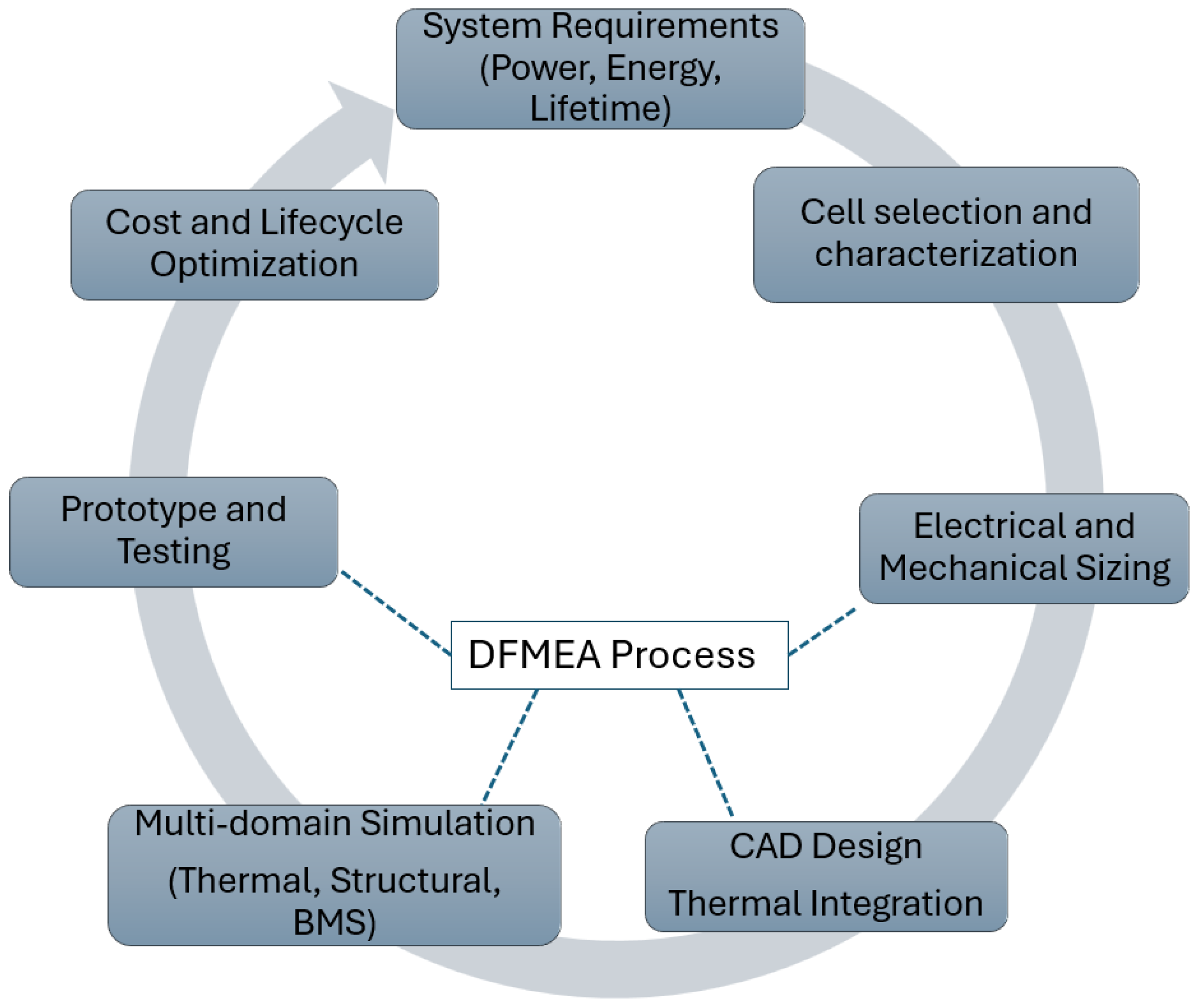
Figure 1. Iterative design methodology for EV and ESS battery systems.
Electricity 06 00063 g001
Figure 2. HV schematic of a BDU with two breakers replacing the contactors.
Electricity 06 00063 g002
Figure 3. An example of the hardware architecture of BMS using OpenECU as primary controller for the EV application.
Electricity 06 00063 g003
Figure 4. High-level overview of the BMS software components and functions.
Electricity 06 00063 g004
Figure 5. (a) Battery pack outline showing eight modules, BDU and BMS. (b) Exploded view of the full-sized 36P12S module CAD model. (c) 6P12S prototype CAD model (Sectional (Z-axis) view on the left half shows serpentine cooling channels). (d) Assembled prototype (insulation sheet and enclosure not shown).
Electricity 06 00063 g005
Figure 6. (a) Simulation setup showing the serpentine cooling channels, inlet and outlet. (b) Temperature rise of the hottest and coolest cell during DCFC with active cooling and without active cooling.
Electricity 06 00063 g006
Figure 7. (a) CAD model of the BDU showing the internal components. (b) Assembled prototype with all control wires.
Electricity 06 00063 g007
Figure 8. Prototype BMS development board.
Electricity 06 00063 g008
Figure 9. (a) Top-level BMS architecture. (b) Example of some BMS functions implemented inside ’Controls’ subsystem in Matlab Simulink (Some blocksets are recreated from OpenECU library blocksets).
Electricity 06 00063 g009
Figure 10. An example of BMS in operation showing the initialization and operation of the contactor.
Electricity 06 00063 g010
Table 1. Comparison of key design metrics for EV and ESS battery systems.
ParameterEV TargetESS Target
Energy Density (Gravimetric)>275 Wh/kgNot a primary focus
Energy Density (Volumetric)>650 Wh/LNot a primary focus
Charging/Discharge Rate≤15 min to 80% SOC; up to 10C2–4 h discharge duration
Cycle Life≥1000 cycles at 80% DoDLong duration, varies by use case
Calendar Life≥10 years≥10–15 years
System Voltage400 V/800 V600–1500 V
Round-Trip Efficiency>90%>90%
Operating Temperature−30 ° C to +55 ° CTypically −20 ° C to +50 ° C
Type approval/Safety StandardsUN 38.3, ISO 26262, UL 2580UL 9540A [15], IEC 62933
Environmental ProtectionIP67 or higherIP65 or higher
Communication ProtocolsCAN, ISO 15118 [16]Modbus, DNP3, IEC 61850 [17]
System IntegrationVehicle systems, charging infrastructureSCADA/EMS platforms
Cybersecurity FocusBasic vehicle-level protectionCritical for grid-tied systems
Cost Target<$75/kWh$124–$296/kWh (LCOS, 4-h)
Table 2. Comparison of lithium-ion cell formats for EV and ESS applications.
ParameterCylindricalPrismaticPouch
Energy Density (Wh/kg)Medium–HighMediumHigh
Volumetric EfficiencyModerateHighHigh
Thermal UniformityHighModerateLow
Mechanical RobustnessHighMediumLow
Manufacturing MaturityHighHighModerate
Packaging EfficiencyMediumHighLow
EV Deployment
ESS DeploymentNicheMainstreamDense racks
Table 3. Battery pack design requirements.
ParameterSpecification
Operating Voltage Range250–420 V
Installed Energy60 kWh
Fast Charge Time36 min (to 80% SOC)
Maximum Charge Power60 kW
Maximum Discharge Power175 kW (10 s at 20% SOC)
Continuous Discharge Rate1C
Gross Weight450 kg
BMS Measurement Accuracy±3%
Target Lifetime>10 years
Disclaimer/Publisher’s Note: The statements, opinions and data contained in all publications are solely those of the individual author(s) and contributor(s) and not of MDPI and/or the editor(s). MDPI and/or the editor(s) disclaim responsibility for any injury to people or property resulting from any ideas, methods, instructions or products referred to in the content.