
Low-Cost Active Power Filter Using Four-Switch Three-Phase Inverter Scheme


Abstract
1. Introduction
2. Objective and Contribution of the Paper
2.1. Main Objective
2.2. Main Contribution
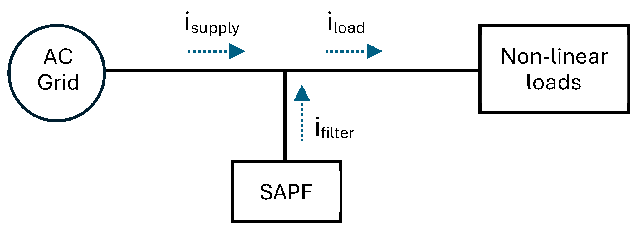
3. Concept of Shunt Active Power Filter
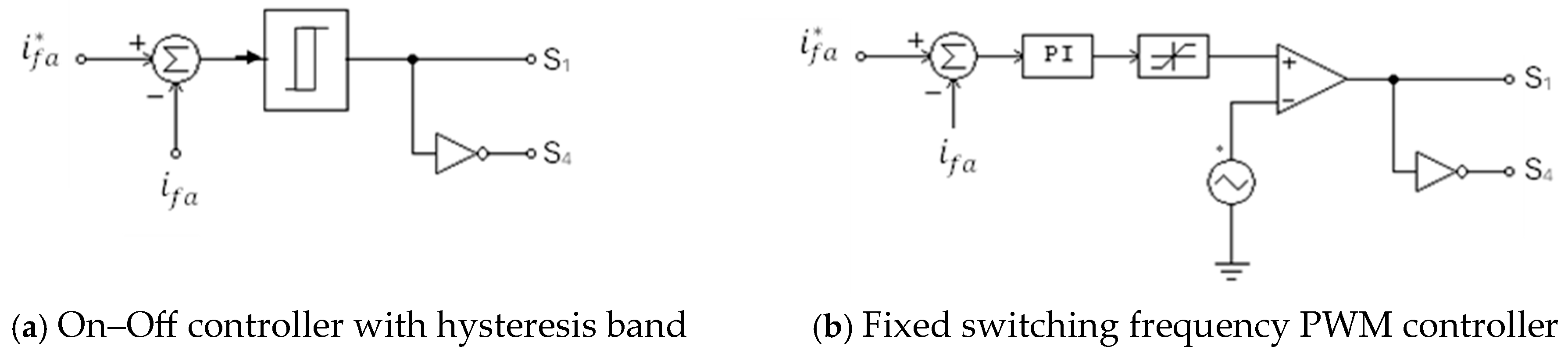
4. Reference Grid Currents Generation Methods
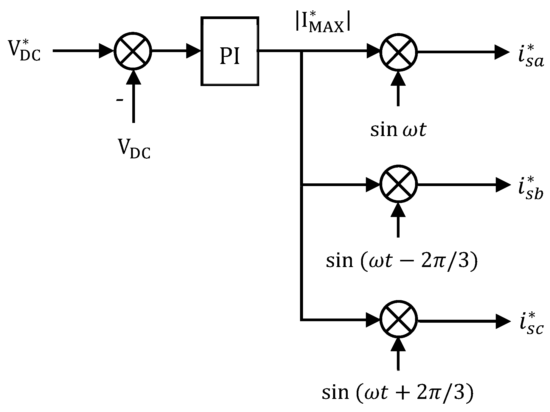
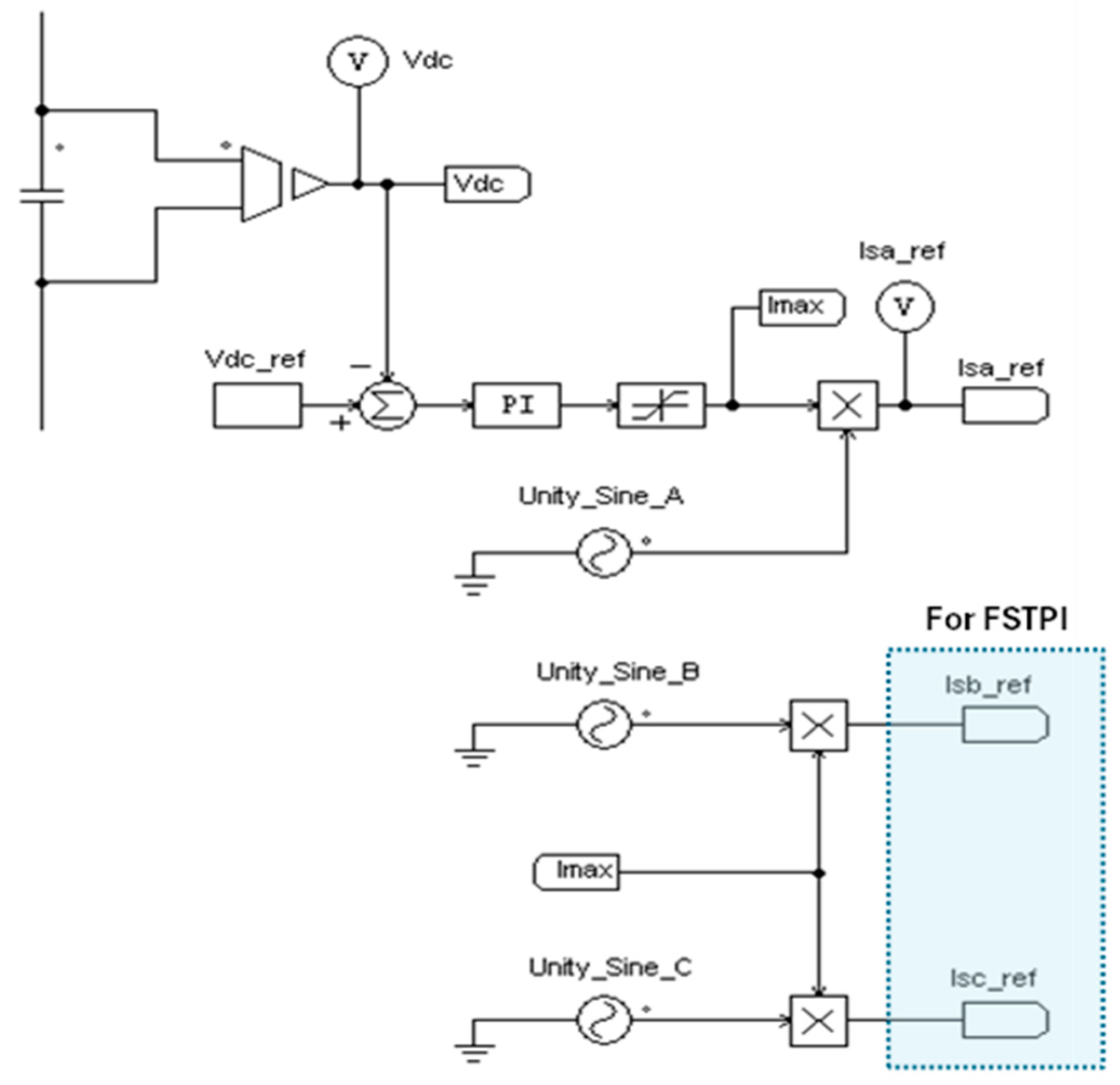
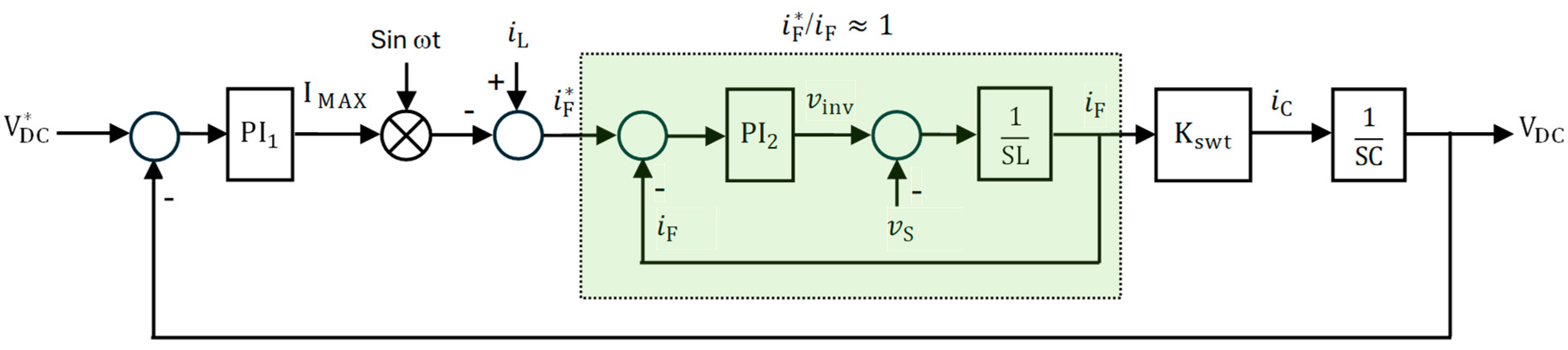
4.1. Based on Closed-Loop Control of DC Link Voltage of the SAPF
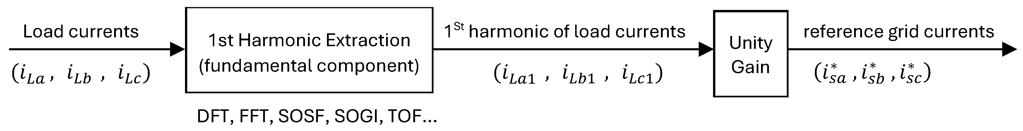
4.2. Based on Calculation of the First Harmonics of the Load Current
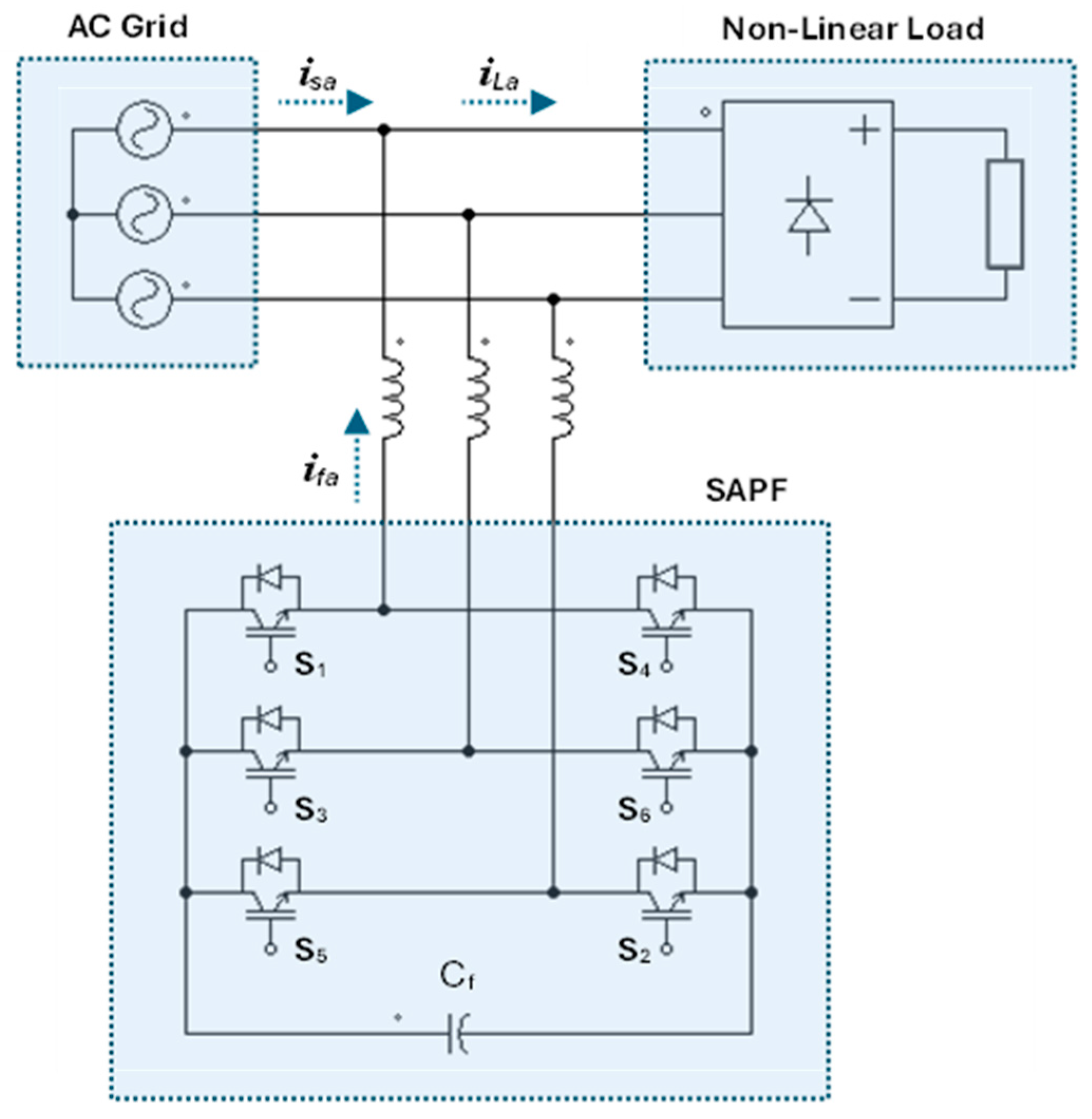
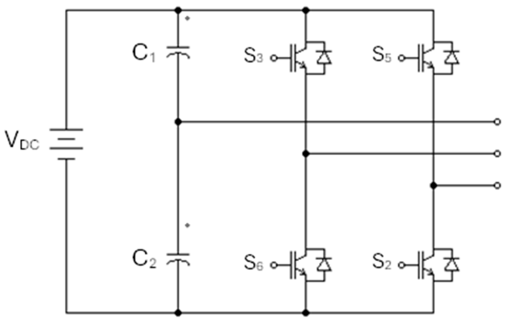
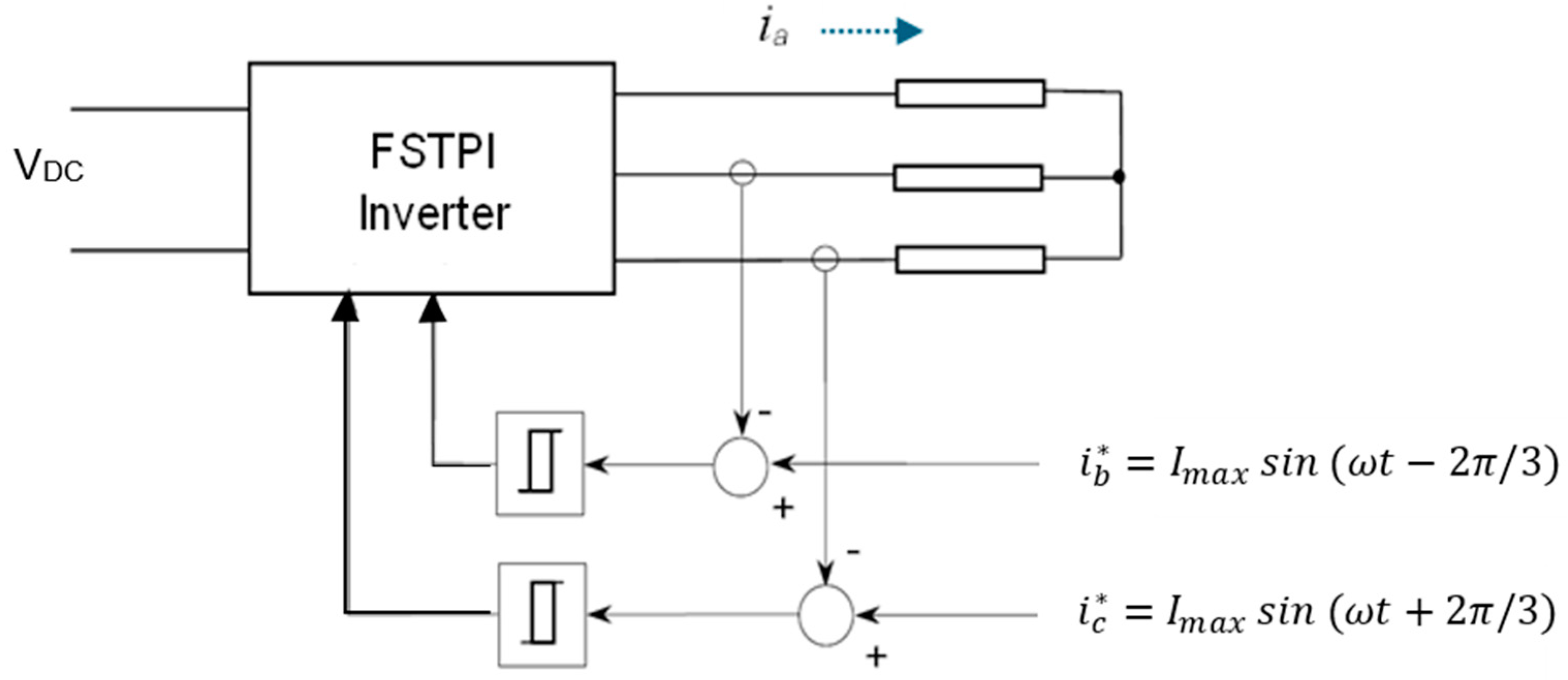
5. Principle of Operation of FSTPI
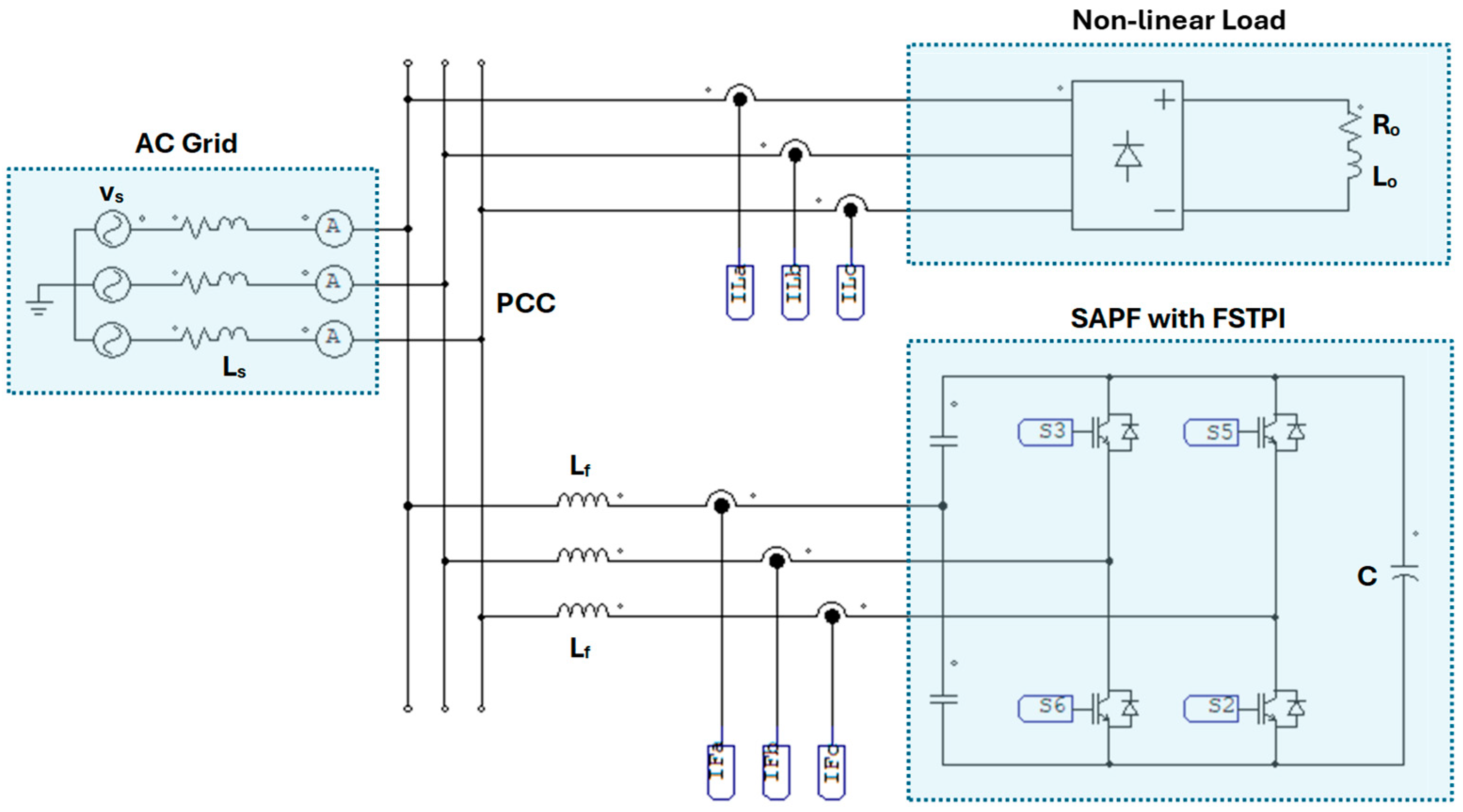
6. Investigated Schemes of SAPFs with FSTPI and SSTPI Using PSIM
6.1. Hardware Modeling in PSIM
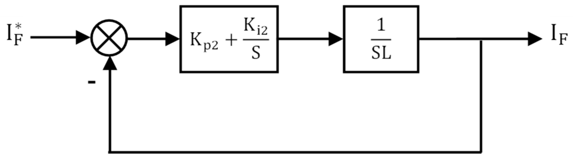
6.2. Design of PI Controllers
6.3. Simulation Parameters
7. Obtained Results and Discussions
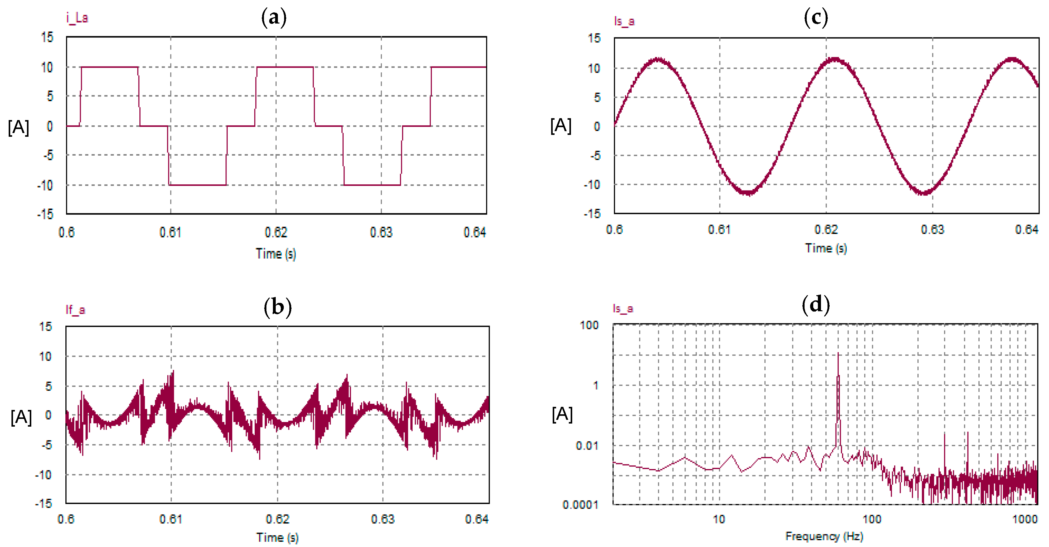
7.1. (Nonlinear Load): 3-Φ Diode Bridge Rectifier Feeding a Highly Inductive Load
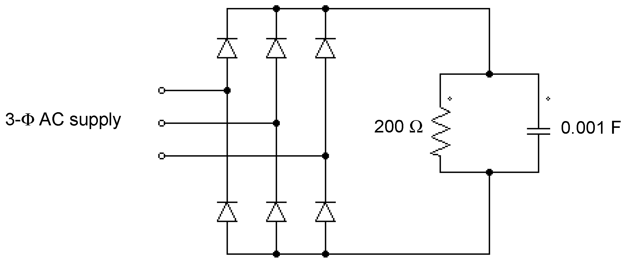
7.2. (Highly Distorted Current): 3-Φ Diode Bridge Rectifier Loaded with a Capacitive Load
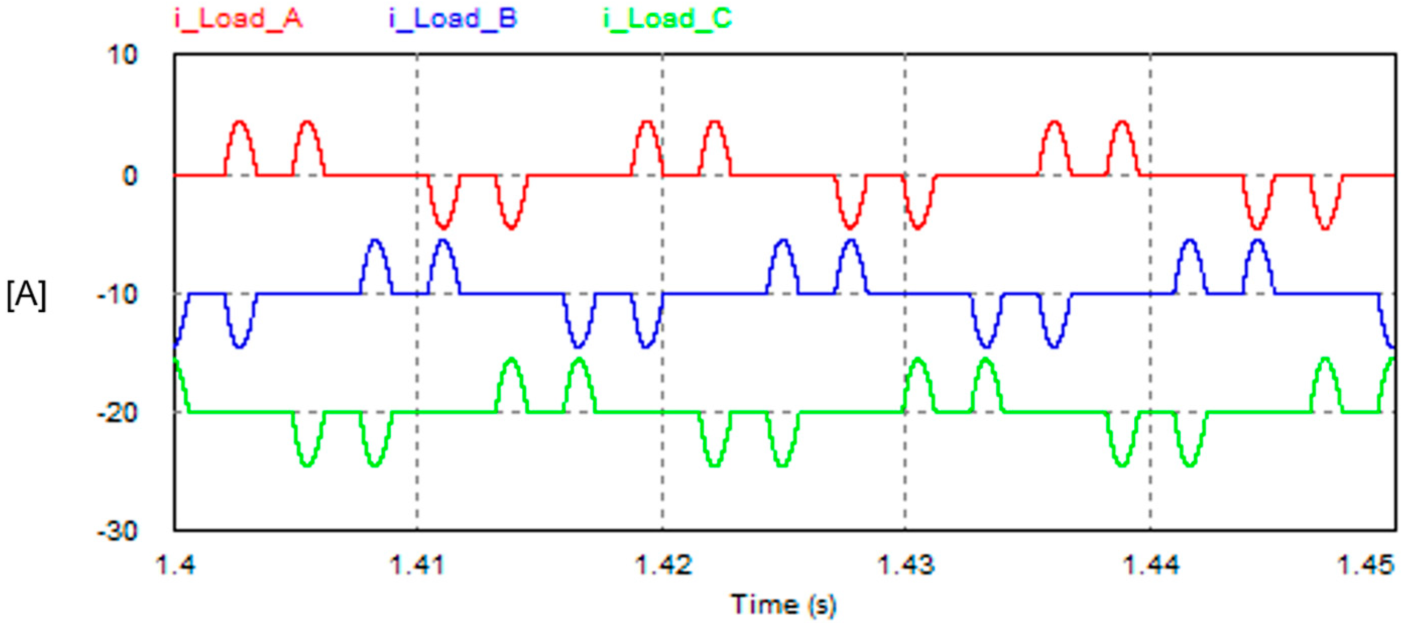
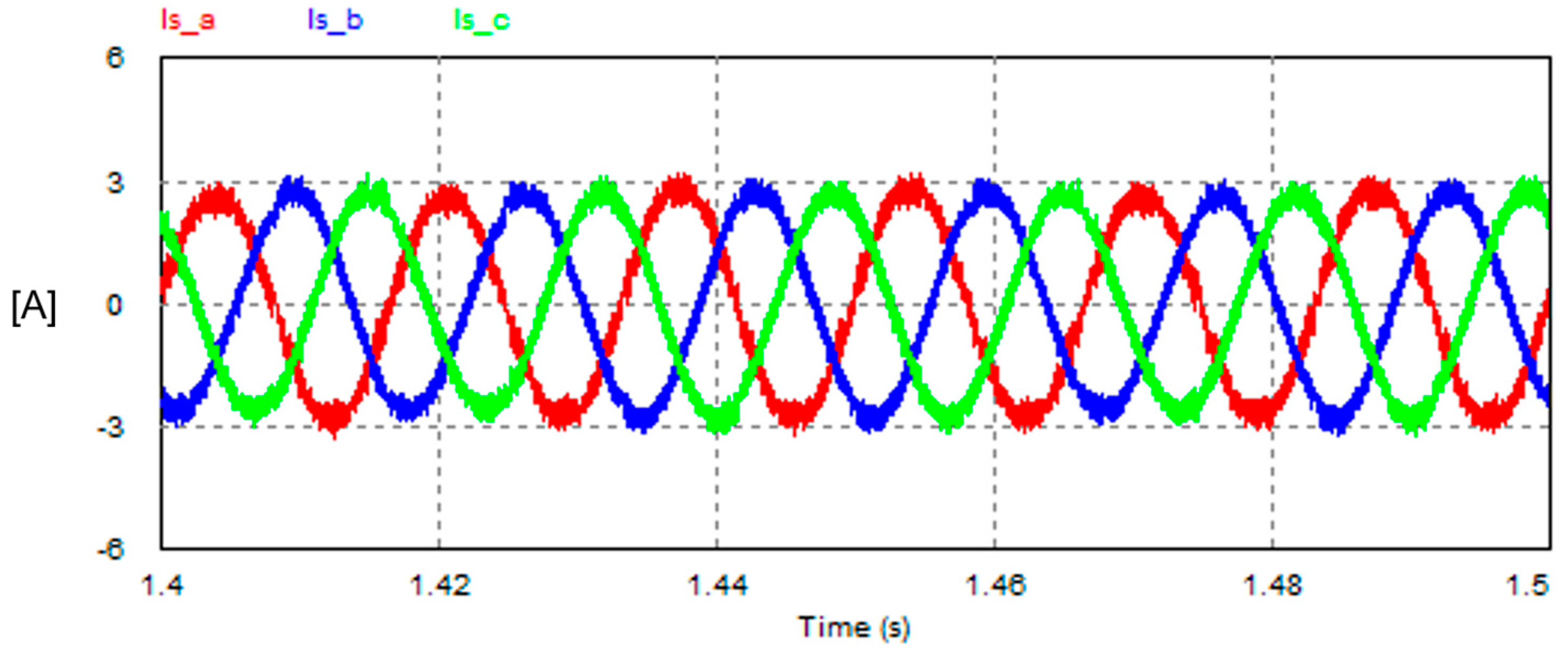
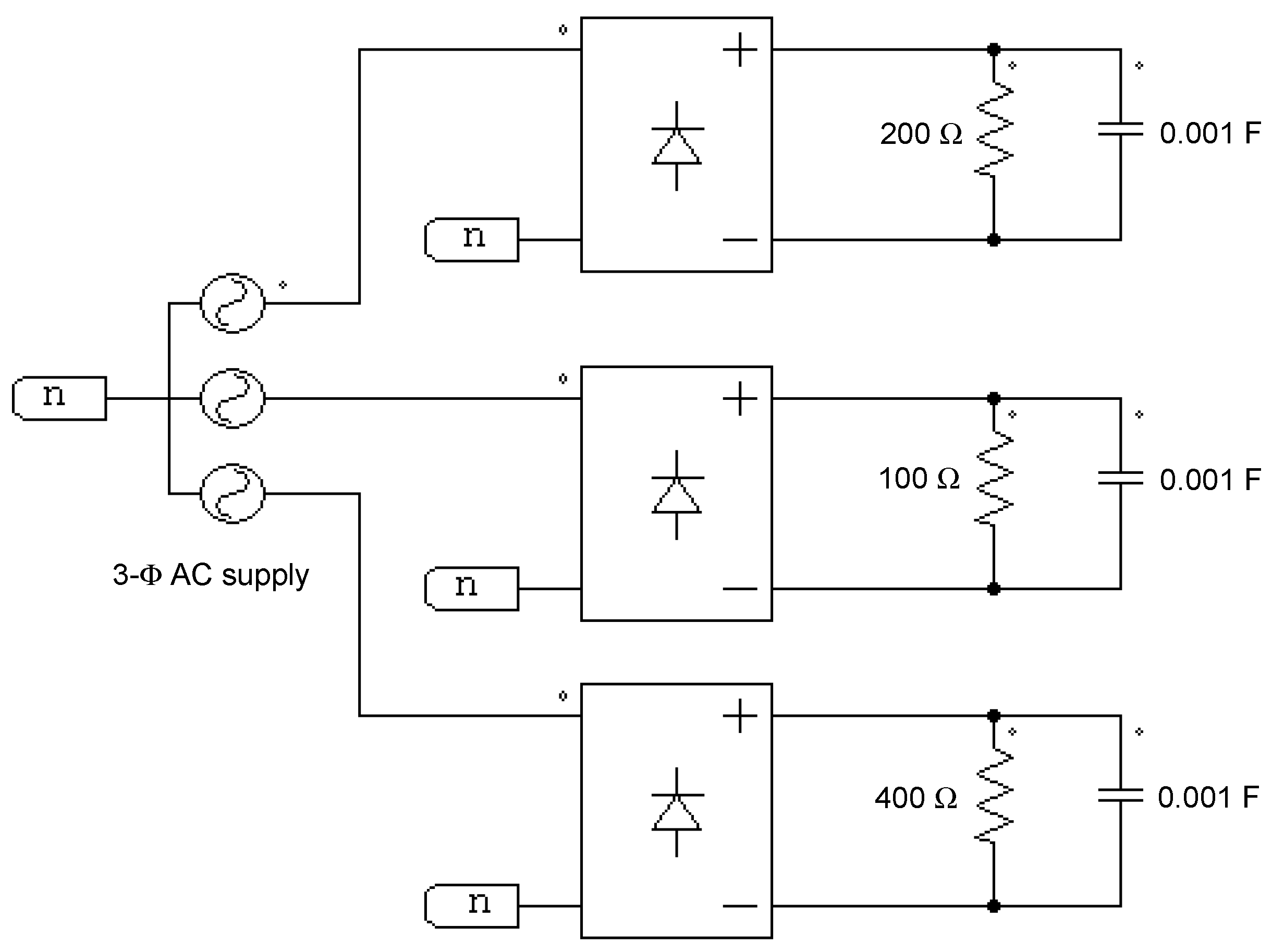
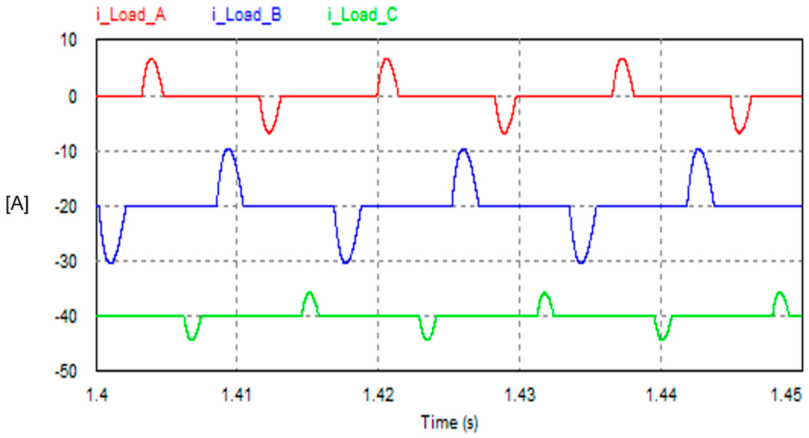
7.3. (Unbalanced Non-Linear Load): Three 1-Φ Diode Bridge Rectifiers Loaded with Unequal Capacitive Loads
8. Conclusions
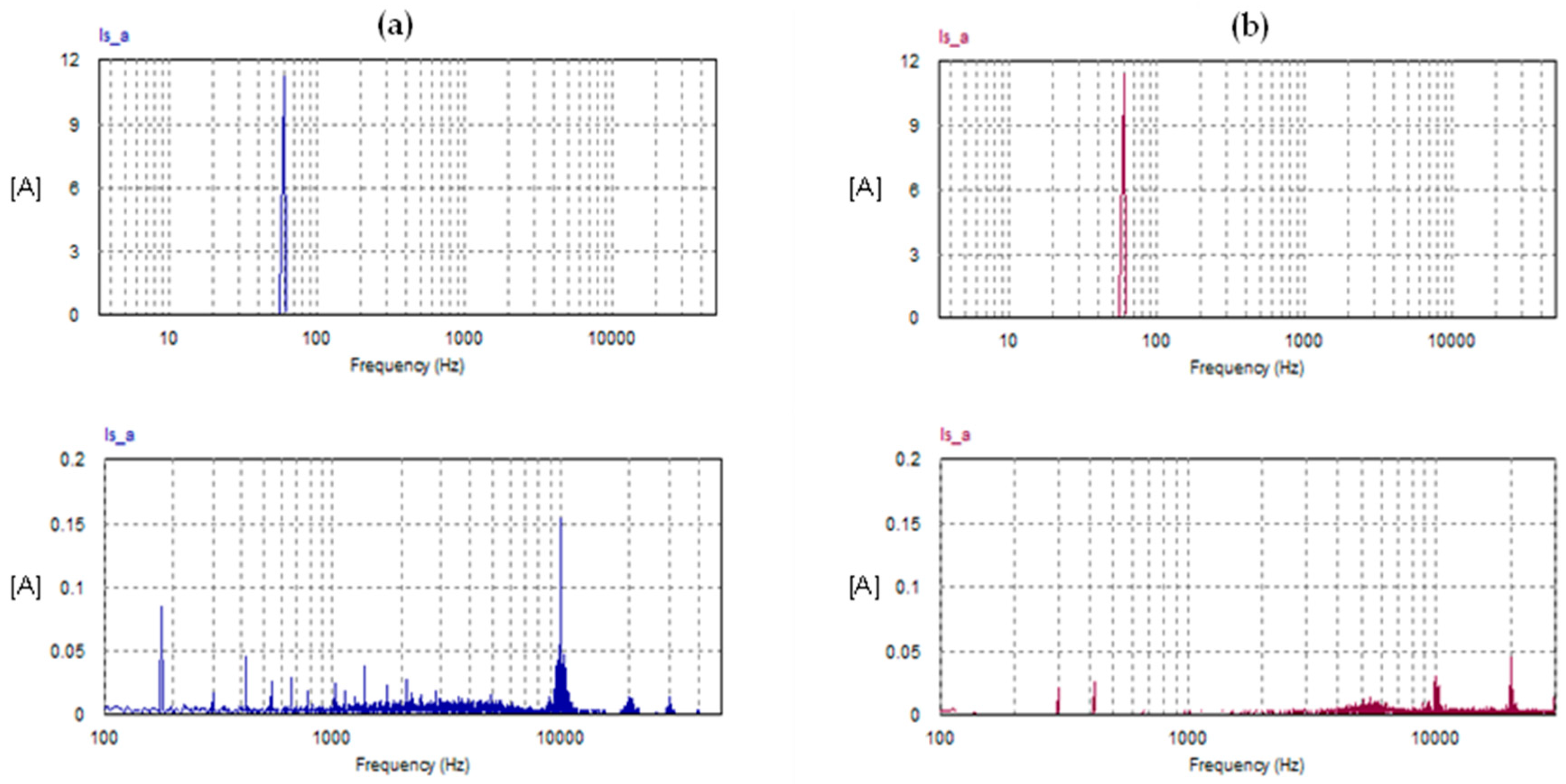
- The total harmonic distortion (THD) of the grid current with the FSTPI scheme is 3.2%, while with the SSTPI scheme, it is 2.05%. Thus, the THD with the FSTPI is higher by 56%.
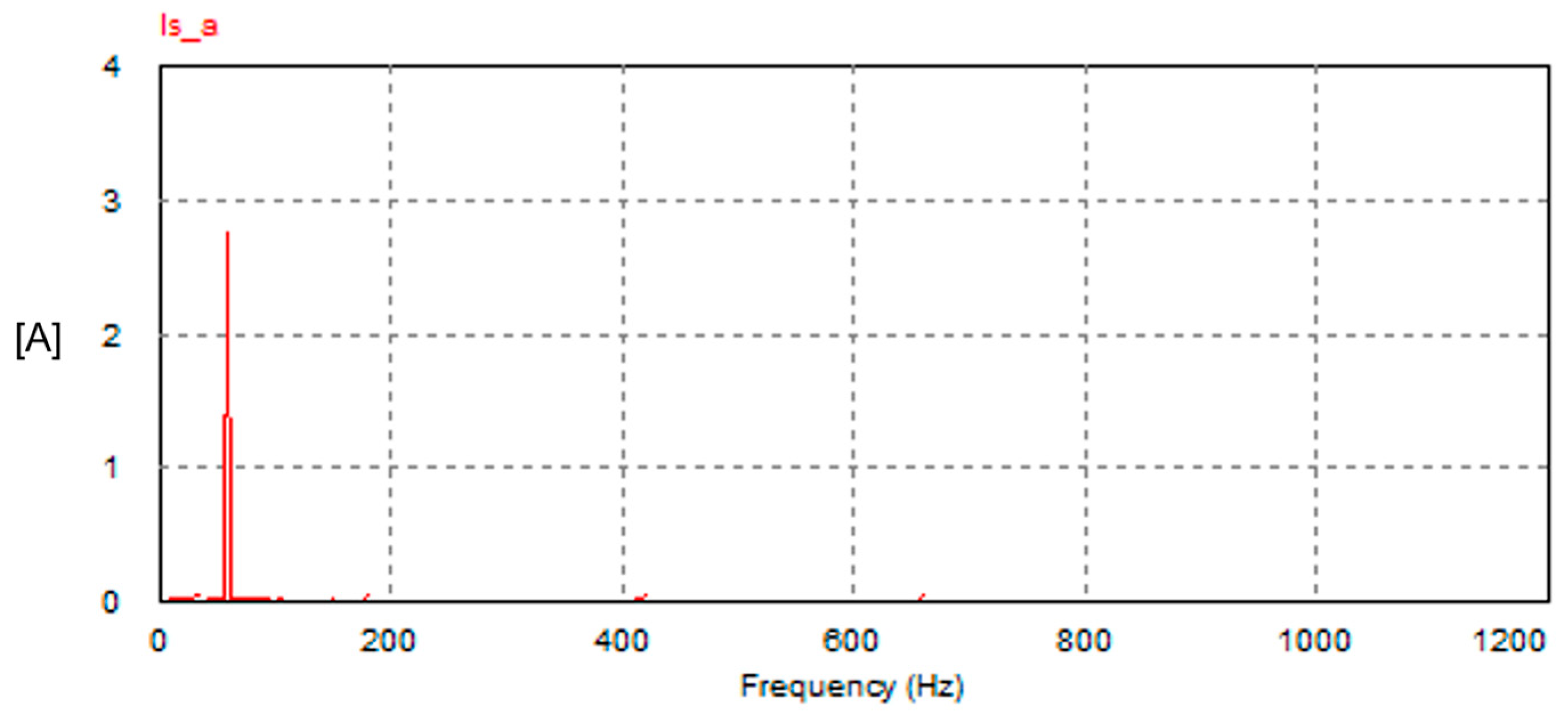
- The amplitude of the fifth-order harmonic in the supply current does not exceed 1% of the fundamental component in both schemes. In the FSTPI, the ratio (I5/I1) is 0.66%, while the corresponding ratio in the SSTPI is 0.18%.
- The input power factor (PF) in both schemes is almost unity (0.99).
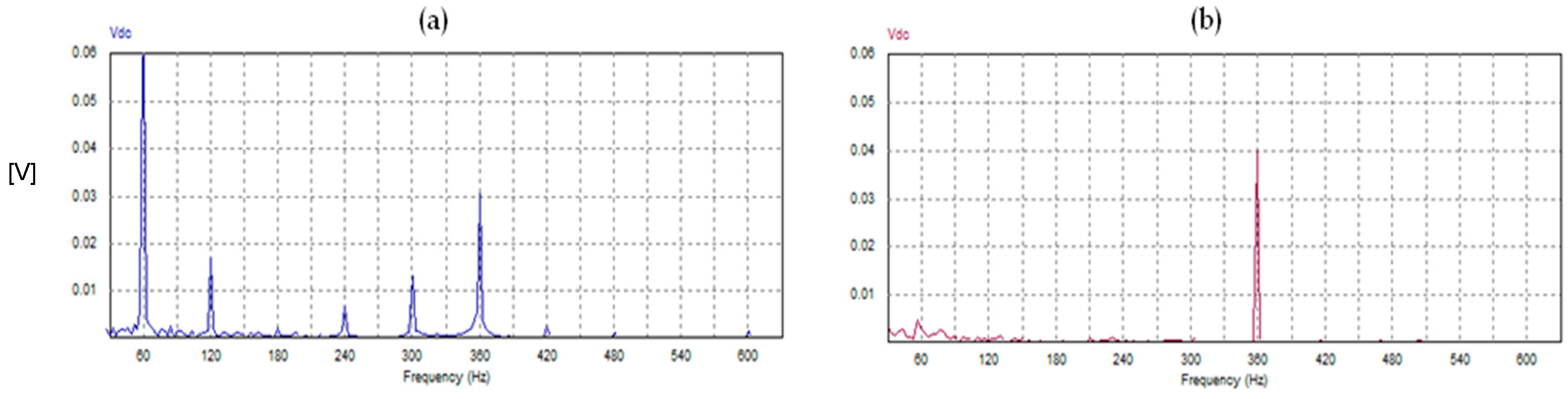
- Both schemes of SAPFs produce the same average value of the DC link voltage, which is well-regulated to the desired set point (600 V) thanks to the PI voltage controllers of the outer voltage control loops. However, in the case of the FSTPI scheme, the dominant low-order harmonic of the DC link voltage pulsates at the supply frequency (60 Hz). Meanwhile in the case of the SSTPI, the dominant low-order harmonic of the DC link voltage pulsates at a rate six times the supply frequency (360 Hz).
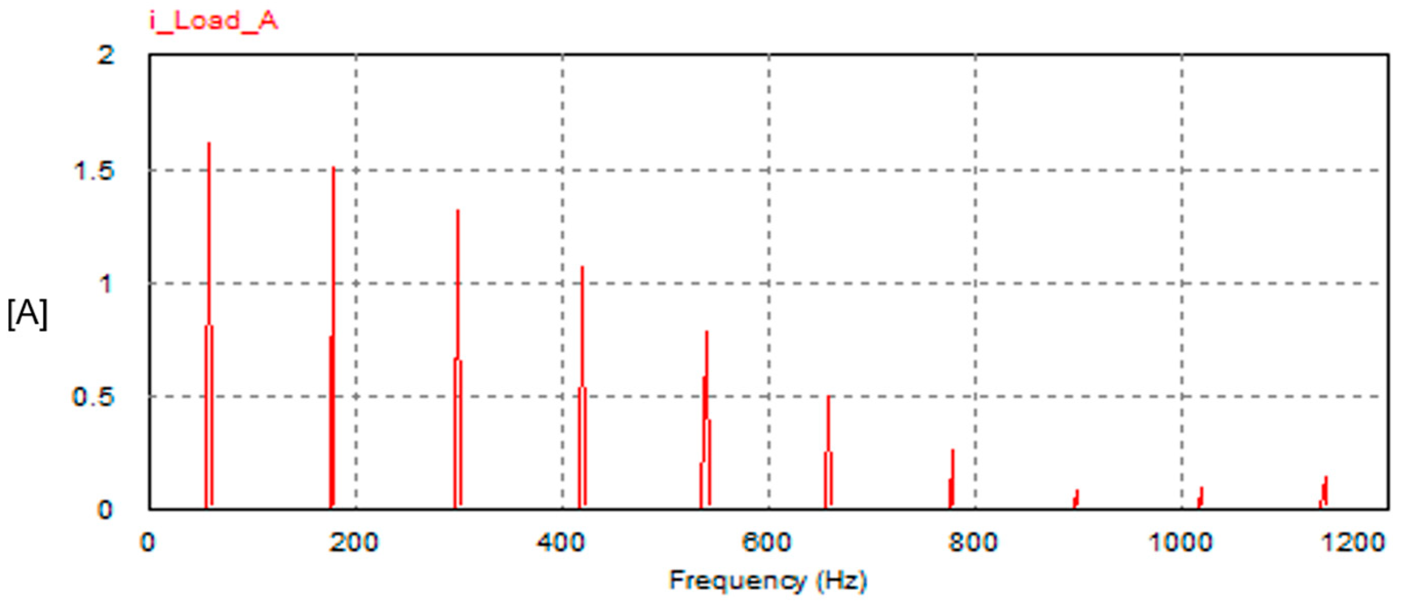
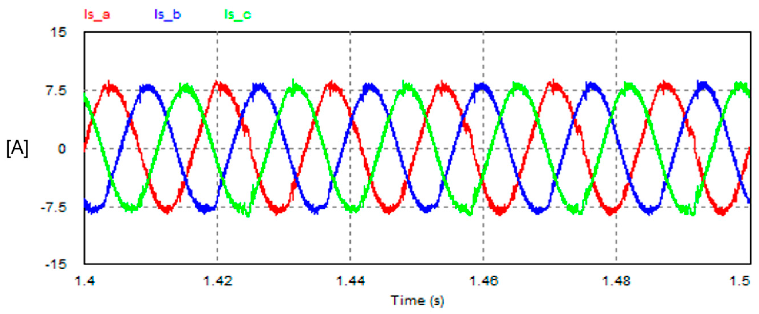
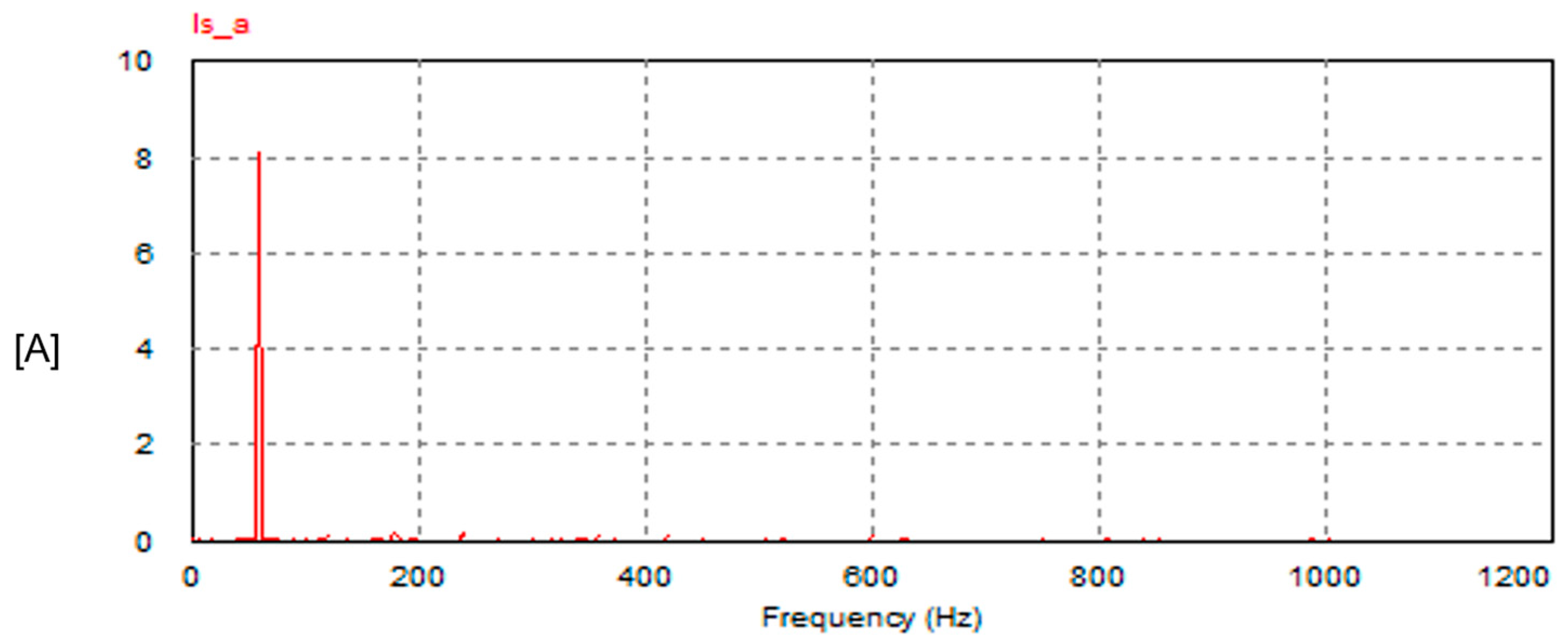
- The operation of the FSTPI-based SAPF is reliable and effective under highly distorted loading conditions. After compensation, the THD of the grid currents is extremely improved from 125% to 9%, meanwhile the PF is improved from 0.624 to 0.99.
- The SAPF using the FSTPI is effective in compensating for the unbalanced nonlinear loading condition whose current waveform is highly distorted. The THD improves from 153% to 6.2%, meanwhile the PF improves from 0.544 to 0.99.
- Compared with the SSTPI scheme, the proposed SAPF with the FSTPI scheme provides a reduction in the number of power transistors, freewheeling diodes, and auxiliary driver/isolation circuits by 33.33%. Moreover, the number of Hall effect current and voltage transducers that are needed to implement the SAPF with the FSTPI is reduced by the same amount (33%), which reduces the overall capital cost of the SAPF system.
- The FSTPI scheme requires an additional two capacitors instead of two power semiconductor switches. Fortunately, the price of power capacitors is less than the price of power transistors, especially if their type is SiC.
- The FSTPI scheme provides a reduction in conduction power losses of 33% for the same inverter current compared with its SSTPI counterpart.
- Compared with the SSTPI scheme, the FSTPI suffers from an increase in switching power losses by 15.4% when both inverters operate at the same PWM switching frequency and the same inverter output voltage.
- Although the conventional SAPF scheme with the SSTPI provides a relatively superior performance in terms of AC currents drawn from the grid with a lower THD and a lower harmonic content of the DC link voltage, the SAPF based on the FSTPI is considered to be competitive with the conventional SAPF scheme in terms of the reduced number of power semiconductor devices and transducers needed to implement the overall system.
- The satisfactory performance achieved by the SAPFs with the FSTPI scheme makes the FSTPI scheme feasible and applicable when price reduction and fabricating economic SAPFs are of major concern.
Funding
Data Availability Statement
Conflicts of Interest
Nomenclature
| Abbreviations | |
| APF | Active power filter |
| FSTPI, B4 | Four-switch three-phase inverter |
| FFT | Fast Fourier transform |
| FO-PID | Fractional-order PID |
| IGBT | Insulated gate bipolar transistor |
| LOH | Low-order harmonic |
| MOSFET | Metal–oxide field-effect transistor |
| THD | Total harmonic distortion |
| PCC | Point of common coupling |
| PF | Power factor |
| PLL | Phase-locked loop |
| PID | Proportional–integral–derivative |
| PWM | Pulse width modulation |
| SAPF | Shunt active power filter |
| SCR | Silicon controlled rectifier |
| SPWM | Sinusoidal PWM |
| SiC | Silicon Carbide |
| SSTPI, B6 | Six-switch three-phase inverter |
| SVM | Space vector modulation |
| VSI | Voltage source inverter |
| WBG | Wide band gap |
| Symbols | |
| Reference filter currents | |
| Reference supply (grid) currents | |
| Instantaneous values of the load currents | |
| Instantaneous values of the 1st harmonic of the nonlinear load currents | |
| Peak value of the reference supply current | |
| Reference DC link voltage | |
| Instantaneous value of DC link voltage | |
| S1, S3, S5, S4, S6, S2 | Switching signals of the six transistors of SSTPI |
| S3, S5, S6, S2 | Switching signals of the four transistors of FSTPI |
| C1, C2 | Capacitors of the 1st branch of FSTPI |
| C | DC link capacitor of SAPFs |
| Inductance of the inductor connected to the output of the SAPF | |
| Inductance of the AC supply (grid inductance) | |
| AC supply voltage | |
| Kswt | Switching function of the inverter |
| Transfer functions of PI controllers of the voltage and current loops, respectively | |
| Open-loop gain function of the voltage control loop | |
| Open-loop gain function of the current control loop | |
| Closed-loop transfer function of the voltage control loop | |
| Closed-loop transfer function of the current control loop | |
| Proportional gains of the voltage and current controllers, respectively | |
| , | Integral gains the voltage and current controllers, respectively |
| Damping ratios of voltage and current control loops, respectively | |
| Settling times of voltage and current control loops, respectively | |
| Natural frequencies of voltage and current control loops, respectively | |
| Supply radian frequency | |
Appendix A
Appendix A.1. Derivation of PI Controller’s Gains of DC Voltage Control Loop
Appendix A.2. Derivation of PI Controller’s Gains of Inner Current Control Loop
Appendix B
Comparative Analysis of SAPFs Using FSTPI and SSTPI Schemes

| Item | SSTPI | FSTPI | |
|---|---|---|---|
| Number of devices | Transistors and freewheeling diodes | 6 | 4 |
| Isolation and driving circuits | 6 | 4 | |
| Hall effect current transducers | 3 | 2 | |
| Hall effect voltage transducers (for DC link voltage measurement) | 1 | 1 | |
| Phase-locked loop (PLL) or Hall effect voltage transducers (for unity gain signal synchronized with the AC grid voltage) | 3 | 2 | |
| Capacitors (DC link and one branch of the inverter power circuit) | 1 | 3 | |
| Inverter output voltage | Normalized line–line or line–neutral (at the same DC link voltage) | 1 | |
| Normalized required DC link voltage (for the same inverter output voltage | 1 | ||
| Power losses | Normalized conduction losses (for the same inverter load current) | 1 | 0.666 |
| Normalized switching losses (for the same inverter output voltage and current and at the same PWM switching frequency) | 1 | 1.154 | |
| Normalized total power losses | 1 | = 0.91 | |
| Power quality | Input PF | 0.99 | 0.99 |
| Best achieved THD of AC grid current (at the same switching frequency, sampling time, passive filtering components) | 2% | 3% | |
| Item | Description | Percentage |
|---|---|---|
| Saving in the devices | Transistors and freewheeling diodes | 33.3% |
| Isolation and driving circuits | 33.3% | |
| Hall effect current transducers | 33% | |
| Phase-locked loop (PLL) or Hall effect voltage transducers (for unity gain signal synchronized with the AC grid voltage) | 33.3% | |
| Additional cost of capacitors | Two capacitors of one arm (branch of no power transistors) | 200% |
| Undesired reduction in the inverter output voltage | For the same DC link voltage | |
| Required additional increase in DC link voltage | For the same inverter output voltage | 73.2% |
| Reduction (saving) in conduction power losses | For the same load current | 33.3% |
| Increasing in switching power losses | At the same PWM switching frequency and for the same inverter output voltage and current | |
| Saving in overall power losses | For the same operating conditions |
References
- Wu, Z.; Xu, G.; Zhu, W.; Sheng, G. The Stability Analysis and Control Strategies of Multi-paralleled SAPFs: A Comprehensive Overview. IEEE Trans. Power Electron. 2024, 39, 7444–7457. [Google Scholar] [CrossRef]
- Torabi Jafrodi, S.; Ghanbari, M.; Mahmoudian, M.; Najafi, A.M.G.; Rodrigues, E.; Pouresmaeil, E. A Novel Control Strategy to Active Power Filter with Load Voltage Support Considering Current Harmonic Compensation. Appl. Sci. 2020, 10, 1664. [Google Scholar] [CrossRef]
- Buła, D.; Michalak, J.; Zygmanowski, M.; Adrikowski, T.; Jarek, G.; Jeleń, M. Control Strategy of 1 kV Hybrid Active Power Filter for Mining Applications. Energies 2021, 14, 4994. [Google Scholar] [CrossRef]
- Kukrer, O.; Komurcugil, H.; Guzman, R.; de Vicuna, L.G. A New Control Strategy for Three-Phase Shunt Active Power Filters Based on FIR Prediction. IEEE Trans. Ind. Electron. 2021, 68, 7702–7713. [Google Scholar] [CrossRef]
- Pichan, M.; Seyyedhosseini, M.; Hafezi, H. A New Dead Beat-Based Direct Power Control of Shunt Active Power Filter With Digital Implementation Delay Compensation. IEEE Access 2022, 10, 72866–72878. [Google Scholar] [CrossRef]
- Zhou, J.; Yuan, Y.; Dong, H. Adaptive DC-Link Voltage Control for Shunt Active Power Filters Based on Model Predictive Control. IEEE Access 2020, 8, 208348–208357. [Google Scholar] [CrossRef]
- Hoon, Y.; Zainuri, M.A.A.M.; Al-Ogaili, A.S.; Al-Masri, A.N.; Teh, J. Active Power Filtering Under Unbalanced and Distorted Grid Conditions Using Modular Fundamental Element Detection Technique. IEEE Access 2021, 9, 107502–107518. [Google Scholar] [CrossRef]
- Nie, X.; Liu, J. Current Reference Control for Shunt Active Power Filters Under Unbalanced and Distorted Supply Voltage Conditions. IEEE Access 2019, 7, 177048–177055. [Google Scholar] [CrossRef]
- Al-Gahtani, S.F.; Nelms, R.M. Performance of a Shunt Active Power Filter for Unbalanced Conditions Using Only Current Measurements. Energies 2021, 14, 397. [Google Scholar] [CrossRef]
- Kumar, R.; Bansal, H.O.; Gautam, A.R.; Mahela, O.P.; Khan, B. Experimental Investigations on Particle Swarm Optimization Based Control Algorithm for Shunt Active Power Filter to Enhance Electric Power Quality. IEEE Access 2022, 10, 54878–54890. [Google Scholar] [CrossRef]
- Muneer, V.; Biju, G.M.; Bhattacharya, A. Optimal Machine-Learning-Based Controller for Shunt Active Power Filter by Auto Machine Learning. IEEE J. Emerg. Sel. Top. Power Electron. 2023, 11, 3435–3444. [Google Scholar] [CrossRef]
- Gao, Y.; Li, X.; Zhang, W.; Hou, D.; Zheng, L. A Sliding Mode Control Strategy with Repetitive Sliding Surface for Shunt Active Power Filter with an LCLCL Filter. Energies 2020, 13, 1740. [Google Scholar] [CrossRef]
- de Rossiter Correa, M.B.; Jacobina, C.B.; da Silva, E.R.C.; Lima, A.M.N. A General PWM Strategy for Four-Switch Three-Phase Inverters. IEEE Trans. Power Electron. 2006, 21, 1618–1627. [Google Scholar] [CrossRef]
- Kim, G.-T.; Lipo, T.A. VSI-PWM rectifier/inverter system with a reduced switch count. IEEE Trans. Ind. Appl. 1996, 32, 1331–1337. [Google Scholar] [CrossRef]
- Jacobina, C.B.; da Silva, E.R.C.; Lima, A.M.N.; Ribeiro, R.L.A. Vector and scalar control of a four switch three phase inverter. In Proceedings of the IAS ’95. Conference Record of the 1995 IEEE Industry Applications Conference Thirtieth IAS Annual Meeting, Orlando, FL, USA, 8–12 October 1995; Volume 3, pp. 2422–2429. [Google Scholar] [CrossRef]
- Ledezma, E.; Munoz-Garcia, A.; Lipo, T.A. A dual three-phase drive system with a reduced switch count. In Proceedings of the Conference Record of 1998 IEEE Industry Applications Conference. Thirty-Third IAS Annual Meeting (Cat. No.98CH36242), St. Louis, MO, USA, 12–15 October 1998; Volume 1, pp. 781–788. [Google Scholar] [CrossRef]
- Liang, D.T.W. Novel modulation strategy for a four-switch three-phase inverter. In Proceedings of the Second International Conference on Power Electronics and Drive Systems, Singapore, 26–29 May 1997; Volume 2, pp. 817–822. [Google Scholar] [CrossRef]
- Correa, M.B.R.; Jacobina, C.B.; Lima, A.M.N.; Da Silva, E.R.C. A new approach to generate PWM patterns for four-switch three-phase inverters. In Proceedings of the 30th Annual IEEE Power Electronics Specialists Conference. Record. (Cat. No.99CH36321), Charleston, SC, USA, 1 July 1999; Volume 2, pp. 941–946. [Google Scholar] [CrossRef]
- Guo, F.; Qiao, J.; Jia, T.; Wang, L. Control strategy for three-phase four-switch active power filter based on positive sequence extraction in stationary coordinate fundamental reference frame. J. Phys. Conf. Ser. 2023, 2656, 012022. [Google Scholar] [CrossRef]
- Hasim, A.S.B.A.; Dardin, S.M.F.B.S.M.; Ibrahim, Z.B. Kalman Filters for Reference Current Generation in Shunt Active Power Filter (APF). In Kalman Filters–Theory for Advanced Applications; InTech: London, UK, 2018. [Google Scholar] [CrossRef]
- Chedjara, Z.; Massoum, A.; Wira, P.; Safa, A.; Gouichiche, A. A fast and robust reference current generation algorithm for three-phase shunt active power filter. Int. J. Power Electron. Drive Syst. 2021, 12, 121–129. [Google Scholar] [CrossRef]
- Chauhan, S.K.; Shah, M.C.; Tiwari, R.R.; Tekwani, P.N. Analysis, design and digital implementation of a shunt active power filter with different schemes of reference current generation. IET Power Electron. 2014, 7, 627–639. [Google Scholar] [CrossRef]
- Hasim, A.S.A.; Ibrahim, Z.; Talib, M.H.N.; Dardin, S.M.F.S.M. Three-Phase Reference Current Generator Employing with Kalman Filter for Shunt Active Power Filter. J. Electr. Eng. Technol. 2017, 12, 151–160. [Google Scholar] [CrossRef]
- Abdusalam, M.; Poure, P.; Karimi, S.; Saadate, S. New digital reference current generation for shunt active power filter under distorted voltage conditions. Electr. Power Syst. Res. 2009, 79, 759–765. [Google Scholar] [CrossRef]
- IEEE Std. 519-2014; IEEE Recommended Practice and Requirements for Harmonic Control in Electric Power Systems. (Revision of IEEE Std 519-1992). IEEE: Piscataway, NJ, USA, 2014; pp. 1–29.
- IEEE. IEEE Application Guide for IEEE Standard 1547; IEEE Standard for Interconnecting Distributed Resources with Electric Power Systems; IEEE: Piscataway, NJ, USA, 2009; Volume 1547, pp. 1–207. [Google Scholar]
- IEEE Standard 1459-2010; IEEE Standard Definitions for the Measurement of Electric Power Quantities Under Sinusoidal, Nonsinusoidal, Balanced, or Unbalanced Conditions. IEEE: Piscataway, NJ, USA, 2010; pp. 1–40.
- Bosch, S.; Staiger, J.; Steinhart, H. Predictive Current Control for an Active Power Filter With LCL-Filter. IEEE Trans. Ind. Electron. 2018, 65, 4943–4952. [Google Scholar] [CrossRef]
- Kashif, M.; Hossain, M.J.; Fernandez, E.; Taghizadeh, S.; Sharma, V.; Ali, S.N.; Irshad, U.B. A Fast Time-Domain Current Harmonic Extraction Algorithm for Power Quality Improvement Using Three-Phase Active Power Filter. IEEE Access 2020, 8, 103539–103549. [Google Scholar] [CrossRef]
- Jana, S.; Srinivas, S. A Computationally Efficient Harmonic Extraction Algorithm for Grid Applications. IEEE Trans. Power Deliv. 2022, 37, 146–154. [Google Scholar] [CrossRef]
- Liu, H.; Hu, H.; Chen, H.; Zhang, L.; Xing, Y. Fast and flexible selective harmonic extraction methods based on the generalized discrete fourier transform. IEEE Trans. Power Electron. 2018, 33, 3484–3496. [Google Scholar] [CrossRef]
- Imam, A.A.; Sreerama Kumar, R.; Al-Turki, Y.A. Modeling and Simulation of a PI Controlled Shunt Active Power Filter for Power Quality Enhancement Based on P-Q Theory. Electronics 2020, 9, 637. [Google Scholar] [CrossRef]


| Parameter | Value |
|---|---|
| AC supply () | 3-Φ: 208 V/60 Hz |
| DC bus capacitor (C) | 4 mF |
| FSTPI capacitors (C1, C2) | 1 mF |
| Total inductance (L = Lf + Ls) | 4 mH |
| Switching strategy | SPWM |
| Switching frequency (FSWT) | 10.02 kHz |
| Solver time step | 5 μs |
| DC link voltage (VDC) | 600 V |
| Item | Parameter | SAPF-SSTPI | SAPF-FSTPI |
|---|---|---|---|
| Supply Current | THD | 2.05% | 3.2% |
| First Harmonic | 11.27 | 11.24 A | |
| Third Harmonic | 0.0007 A | 0.077 A | |
| I5/I1 | 0.18% | 0.66% | |
| PF | 0.999 | 0.999 | |
| DC link voltage | Minimum value | 599.96 | 599.85 |
| Maximum value | 600.06 | 600.13 | |
| Dominant LOH | 6 | 1 | |
| First Harmonic | 0.0027 V | 0.064 V | |
| Second Harmonic | 0.0007 V | 0.017 V | |
| Third Harmonic | 0.0005 V | 0.0024 V | |
| Fourth Harmonic | 9.4 × 10⁻⁵ V | 0.0067 V | |
| Fifth Harmonic | 0.0002 V | 0.0131 V | |
| Sixth Harmonic | 0.039V | 0.030 V |
Disclaimer/Publisher’s Note: The statements, opinions and data contained in all publications are solely those of the individual author(s) and contributor(s) and not of MDPI and/or the editor(s). MDPI and/or the editor(s) disclaim responsibility for any injury to people or property resulting from any ideas, methods, instructions or products referred to in the content. |
© 2025 by the author. Licensee MDPI, Basel, Switzerland. This article is an open access article distributed under the terms and conditions of the Creative Commons Attribution (CC BY) license (https://creativecommons.org/licenses/by/4.0/).
Share and Cite
Azab, M. Low-Cost Active Power Filter Using Four-Switch Three-Phase Inverter Scheme. Electricity 2025, 6, 16. https://doi.org/10.3390/electricity6010016
Azab M. Low-Cost Active Power Filter Using Four-Switch Three-Phase Inverter Scheme. Electricity. 2025; 6(1):16. https://doi.org/10.3390/electricity6010016
Chicago/Turabian StyleAzab, Mohamed. 2025. "Low-Cost Active Power Filter Using Four-Switch Three-Phase Inverter Scheme" Electricity 6, no. 1: 16. https://doi.org/10.3390/electricity6010016
APA StyleAzab, M. (2025). Low-Cost Active Power Filter Using Four-Switch Three-Phase Inverter Scheme. Electricity, 6(1), 16. https://doi.org/10.3390/electricity6010016