Abstract
In laser surface remelting (LSR) treatment, only a small region is affected by heat, surpassing the melting temperature, followed by rapid cooling at 103–108 K/s, thus producing an extremely refined microstructure. The treated region shows a more homogeneous microstructure and better mechanical properties as compared to the substrate. Iron is a common impurity found in Al-based alloys but in the 2618 commercial alloy, around 1 wt.% of Fe is intentionally added to improve the high temperature strength and the corrosion resistance. In this work, LSR experiments were performed, by using a CO2 laser operating in a continuous-wave mode, to investigate the influence of process parameters on the treated surface of an as-cast Al-1 wt.% Fe alloy. These parameters encompass work distance (z), laser beam speed (v) and laser average power (P), setting a total of 18 combinations. The configuration of z = 6 mm, v = 500 mm/s and P = 800 W resulted in a molten pool with 710 µm of width for 242 µm of length without major porosities, therefore being the largest stable pool amongst all parameter combinations. The resulting cellular microstructure is shown to have an average interphase spacing of 0.93 ± 0.17 µm, a decrease of about 14 times in relation to that of the substrate. The effects of LSR on microhardness were remarkable, with the remelted track presenting Vickers microhardness of 50.1 ± 2 HV, which corresponds to increase of about 43% as compared to that of the original substrate.
1. Introduction
In commercial Al-based alloys, the usual alloying elements are Si, Mg, Cu and Zn, but Fe is generally present as an impurity, even though in some alloys the presence of Fe is shown to favor the mechanical properties at high temperatures []. The main drawbacks of Fe are the low solubility in Al (maximum of 0.052 wt.% []), leading to the precipitation of brittle intermetallics (IMCs) with low cohesion with the aluminum matrix, e.g., β-AlFeSi and Al3Fe []. Another disadvantage concerns the disturbance on heat treatment efficiency, due to the formation of phases with low diffusivity, such as Al7Cu2Fe and π-Al8Mg3FeSi6 [].
On the other hand, there is an increasing interest in Al–Fe alloys for applications demanding high electrical conductivity [,] and/or good thermal stability []. At room temperature and up to 2 wt.% Fe, the maximum decrease in conductivity is only of 8.1% [], and even after 8 h at 500 °C of solubilization treatment, the stability of the plate-like Al3Fe phase is maintained, without significant changes in the morphology [].
Despite the aforementioned advantages of Al–Fe alloys, the presence of coarse Al3Fe plate-like particles does not provide the required conductivity and mechanical response. Wang et al. [] realized that the tensile properties of an Al-1 wt.% Fe alloy can be potentially improved by changing the morphology of the Al3Fe phase to nanoscale spheres through the rheo-extrusion process. As compared to an as-cast Al-1 wt.% Fe alloy (with plate-like Al3Fe), the ultimate tensile strength and elongation increased by 55% and 12%, respectively. Furthermore, Hou et al. [] established that one of four main requirements for designing Al–Fe wires, with a good balance considering strength and electrical conductivity, is to have the IMCs finely dispersed in the Al-matrix.
Highly refined microstructures can be attained in as-cast alloys by the laser surface remelting (LSR) treatment, where the treated region reaches cooling rates in the range of 103–108 K/s [,]. Due to these extremely high solidification cooling rates, the microstructure can be 100 times more refined than that of a similar untreated sample []. Besides, as the laser equipment can be automatized, components with complex geometries can be treated. Therefore, this work aims to investigate the influence of process parameters of a LSR treatment (average power and scanning speed of laser beam, and beam working distance), on the remelted tracks at the surface of an as-cast Al-1wt.% Fe alloy, in order to evaluate their influence on the dimensions of the molten pool and on the resulting microstructure, as well as on the microhardness of the laser-treated region.
2. Materials and Methods
A previous directionally solidified Al-1 wt.% Fe alloy sample [] was subjected to different combinations of LSR treatment parameters. A CO2 laser machine (Mazak Co., Model-Super Turbo—X510 Champion, Florence, USA performed the treatment on sandblasted sample surfaces. The first adopted parameter was the beam working distance, which is related to beam focusing, being two the chosen distances: z1 = 6 mm and z2 = 8 mm. The second parameter was the average beam power, as it determines the amount of available energy, and the adopted values were P1 = 400 W, P2 = 800 W and P3 = 600 W. The third and final parameter was the laser beam scanning speed set as v1 = 500 mm/min, v2 = 750 mm/min and v3 = 1000 mm/min. A sample tree, numbering all the 18 parameter combinations, is presented in Figure 1.
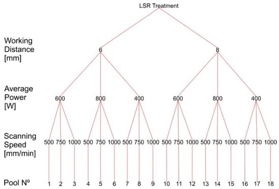
Figure 1.
Experiment sample tree parameters for all produced laser molten pools.
The samples were sectioned transversely with respect to the remelted tracks. The sectioned samples were ground, polished, and etched with a 0.5% HF solution in distilled water. The width and depth of the remelted tracks were measured through optical images obtained with an Olympus inverted metallurgical microscope (Model-GX41, Tokyo, Japan). The microstructure of the track was visualized with the aid of a Zeiss scanning electron microscope (SEM) (Zeiss, Model-EVO-MA15, Oberkochen, Germany) using a back-scattered electron (BSE) detector.
Vickers microhardness was measured on all remelted tracks following the ASTM International (American Society for Testing and Materials) Standard E384-11, using a Shimadzu HMV-2T microhardness tester (Kyoto, Japan) with a 20 gf indentation load and a dwell time of 15 s.
3. Results and Discussion
Transverse optical images of all remelted tracks are shown in Figure 2 and Figure 3. At first glance, the refinement result of the treatment can already be seen, as the cellular microstructure of the substrate can be observed clearly with a horizontal growth direction, although the remelted pool microstructure needs a much higher magnification to be analyzed. Through these images, the quality and dimensions of the pools were analyzed.
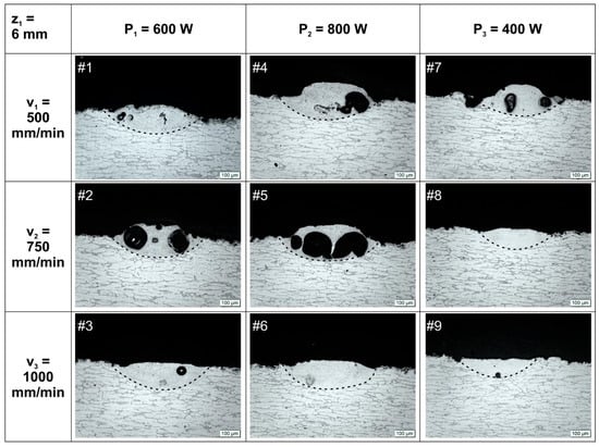
Figure 2.
Optical images of cross sections of laser remelted tracks for beam working distance z1 = 6 mm.
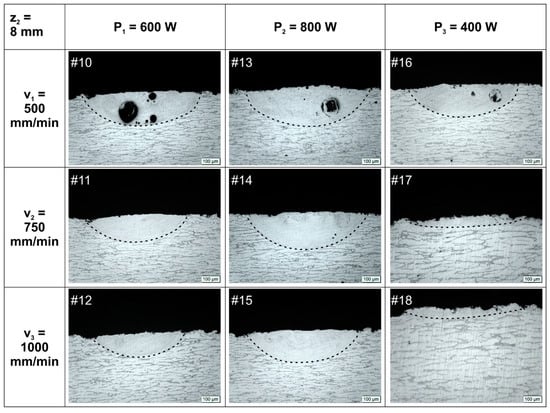
Figure 3.
Optical images of cross sections of laser remelted tracks for beam working distance z2 = 8 mm.
Concerning quality, it is noticed for the most combinations of P and v that those with z1 = 6 mm have generated remelted tracks with defects. Blistering has been responsible for the deformation of these pools. Even for pools #3 (small porosity) and #6 (no apparent blistering) deformations along the whole treated track are present, with the surface bulging atop the laser track (Figure 2). These bulging deformations are indications of blistering occurring in other regions of the LSR treatment, posterior or anterior the visualized cross section. Only pools #8 and #9 have not shown any sign of considerable deformations, so for z1 = 6 mm, promising results are obtained for higher laser beam speeds (v = 750 and 1000 mm/min) and lower average power (P3 = 400 W).
In the case of pools with z2 = 8 mm (Figure 3), the presence of pores can be seen for the lowest beam speed (v1 = 500 mm/min). However, no deformations were identified along the treated track and no bulging is perceptible at the transverse optical images.
Pools #17 and #18 are almost imperceptible due to the low depths of the remelted tracks. A comparison with the pools treated with the lowest P (#7–9 and #16–18) permits the role played by v on energy absorption to be understood. For a lower available amount of energy, low values of v are required for an effective surface treatment; meanwhile, for higher amounts of available energy, high values of v are needed to avoid defects generation such as blistering.
Dimensions (depth and width) of remelted tracks are shown in Figure 4. Tracks that lost their steady-state regular form of half-moon shape have not been considered for dimensional comparison, as well as those with low depth, i.e., thin layers, which have no interest for surface engineering purposes. As expected, increasing the average power or slowing the scanning speed results in higher dimensions. The parameter P has more influence on the dimensions of the laser remelted tracks, especially in the depth, due to the Gaussian power distribution of the laser beam. However, it is possible to obtain larger track widths with lower values of P by decreasing v. So, with a view to achieving appropriate pool dimensions, a combination of both laser beam speed and average power seems to be more effective than using each of the two parameters alone. Table 1 summarizes the dimensions and the quality discussed so far, indicating that pool #13 has the largest dimensions, due to the highest P and slowest v combination, and appropriate z to produce a pool free from defects.
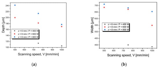
Figure 4.
(a) Depth and (b) width of the pools #8-15 in relation to scanning speed, for different beam working distance and average power.

Table 1.
Quality and dimensions of laser remelted tracks.
As optical images were not enough to analyze the microstructure, SEM images of representative tracks are depicted in Figure 5. The epitaxial growth that characterizes laser remelting treatments can be noticed by the layer marks (indicated by blue arrows) present within the tracks, with growth towards the center of the upper zone of the pool. This kind of growth occurs because the molten pool is contained by its own solid, i.e., during cooling no nucleation occurs [].
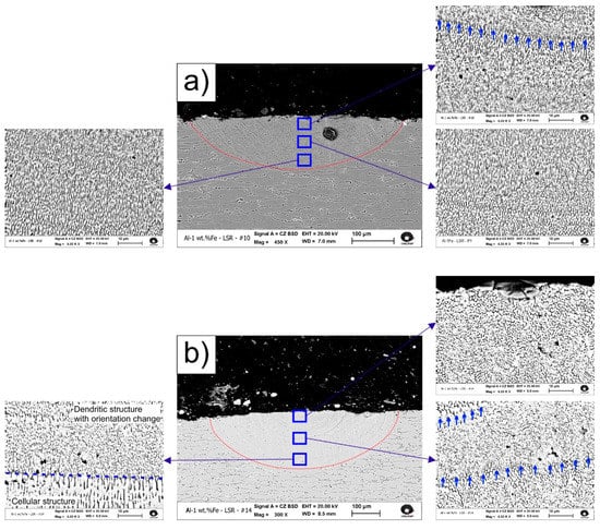
Figure 5.
Microstructure of the remelted track cross section of (a) #10 and (b) #14 samples. Near substrate, middle and near surface zones are highlighted. Layer marks are indicated by blue arrows.
As reported by Gremaud et al. [], the growth rate, vs, can be related to v by vs = v* cos θ (Figure 6), in which θ is the angle between v and vs. As the solidification near the substrate/molten pool interface is characterized by vs approaching zero (θ = 90°), a coarser cellular microstructure (as compared to the average spacing of the track) is identified in this region. With the increase in growth rate from near zero, at the aforementioned interface, to magnitudes near the beam speed towards the surface (θ = 0°), a dendritic growth develops within a micrometer scale away from the interface. Another interesting characteristic associated with vs near zero, is the microstructural growth clearly oriented perpendicular to v, and as vs increases, the growth direction gradually rotates becoming parallel to the beam speed v.
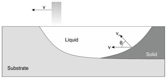
Figure 6.
Schematic representation of the relationship between laser beam speed and growth rate. Adapted from reference [].
In the as-cast Al-1 wt.% Fe alloy, the cellular spacing (λC) ranges from 6.1 to 18.3 μm, following λC = 31*Ṫ−0.55 [], where Ṫ is the solidification cooling rate, while the range of average λC values of each pool was 0.8–1.0 μm. A significant difference in the scale of λC between the as-cast microstructure and that from LSR can be seen in Figure 7. Applying the proposed growth law, the Ṫ value necessary to obtain λC = [0.8–1.0] μm is, at least, more than 12 times higher (570–770 °C/s) than Ṫ of the casting condition. However, in a previous study of LSR of an Al-15 wt.% Cu alloy [], the average microstructural spacing was reported to be 1 μm and the estimated cooling rate around 2 × 10⁵ °C/s. Based on that, the experimental growth law from the as-cast condition is underestimating the real cooling rate of the LSR treatment of the Al-1 wt.% Fe sample. Care should be exercised when growth laws are extrapolated much beyond the original parameters used to formulate them. A more appropriate approach to calculate Ṫ would be that provided by numerical simulations of a heat transfer mathematical model []. Moreover, any instrumentation based on the contact with the tiny molten pool to determine the cooling rate would be invasive. In conventional casting techniques it is not usual to reach such high Ṫ, implying that only in rapid solidification techniques (such as melt spinning, high-pressure casting, spray forming) it would be possible to achieve an extremely refined microstructure, but the capability of these techniques to produce components with large dimensions or complex geometries is very limited. In this sense, the LSR treatment proves to be more advantageous.
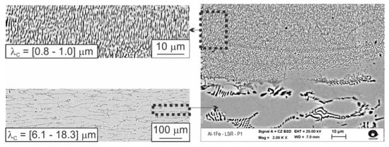
Figure 7.
Microstructural interphase spacing as function of cooling rate (Ṫ).
As expected, the LSR surface treatment has increased the hardness of the alloy because of the refinement of the microstructure. Not only it has increased from a mean value of 35 HV in the substrate to a mean value of 50.1 HV in the remelted tracks, but it is also superior than the expected values based on the extrapolation of the HV experimental equation obtained by Silva et al. [], as presented in Figure 8. This equation is a hardness correlation as a function of the cellular spacing for a directionally solidified Al-1 wt.% Fe alloy. The increase of 43% in microhardness can be attributed to a more refined microstructure and better distribution of the intermetallic compounds. Another reported contribution of LSR treatments concerns the internal stress distribution, since compressive stresses are induced at the surface of the remelted tracks [,].
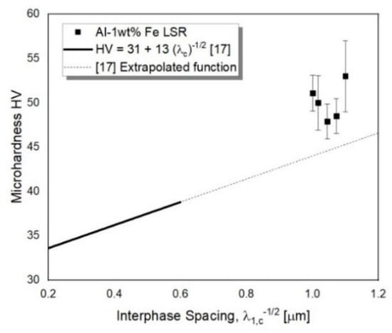
Figure 8.
Microhardness as function of the interphase spacing for an Al-1wt.% Fe laser surface remelting (LSR) treated alloy, compared to results of an experimental equation of a directionally solidified alloy [].
The LSR parameters seem to influence the microstructural spacing within the treated track and, consequently, its microhardness. Lien et al. [] also reported no significant variation in the eutectic spacing while studying LSR of Al-20 wt.% Si alloy samples. The authors utilized laser beam speeds ranging from 1800 mm/min to 7200 mm/min with a fixed laser beam average power of 1200 W. Based on the relation between ΔT (undercooling) and λext (extremum spacing) proposed by Trivedi et al. [], they suggested that the different LSR treatments promoted similar undercooling and microstructural spacing reaching values near λext, and no variance was noticed. The same condition seems to happen in the present work. However, the LSR parameters exert direct control over the track’s dimensions, which is interesting from a manufacturing point of view. The interest is to have a processing map to furnish a desired couple of width and height of remelted tracks that when overlapped, can treat the entire surface of a component. Taking for example, the two best set parameters applied to generate pools #13 (which is the largest pool) and #14 a comparison can be drawn. The laser beam speed of pool #14 is 50% higher than that of #13, with the drawbacks of 11.5% decrease in pool depth and 2.2% decrease in its width. In other words, the parameters of pool #14 are more efficient in terms of time processing, with minimal difference on depth reduction, as compared to the parameters of pool #13.
4. Conclusions
In the present study, a laser surface remelting treatment was performed on Al-1wt.% Fe samples, and the following conclusions can be drawn:
- An operational parameters map, which includes laser beam scanning speed, average power and working distance was proposed permitting treatments that induce defects and those producing pools with higher widths and depths to be assessed.
- LSR operational parameters were shown to directly affect the dimensions of treated pools, however, a direct correlation with the microstructural spacing could not be noticed.
- As compared to the untreated substrate, the microstructural spacing of the remelted tracks was shown to be around 14 times more refined and the microhardness has increased about 43%.
Author Contributions
Conceptualization, R.O. and R.K.; methodology, R.K.; validation, R.O. and K.C.B.C.; formal analysis, R.O. and R.K.; investigation, R.O. and K.C.B.C.; data curation, R.O.; writing—original draft preparation, R.O. and R.K.; writing—review and editing, A.G. and N.C.; visualization, N.C.; supervision, A.G. and N.C. All authors have read and agreed to the published version of the manuscript.
Funding
This research was funded by CNPq—National Council for Scientific and Technological Development and CAPES—Coordenação de Aperfeiçoamento de Pessoal de Nível Superior (Finance code—001).
Acknowledgments
The authors would like to thank LNLS—CNPEM for the use of its dependences.
Conflicts of Interest
The authors declare no conflict of interest.
References
- Lin, B.; Xu, R.; Li, H.; Xiao, H.; Zhang, W.; Li, S. Development of high Fe content squeeze cast 2A16 wrought Al alloys with enhanced mechanical properties at room temperature and elevated temperatures. Mater. Charact. 2018, 142, 389–397. [Google Scholar] [CrossRef]
- Cubero-Sesin, J.M.; Horita, Z. Mechanical properties and microstructures of Al-Fe alloys processed by high-pressure torsion. Metall. Mater. Trans. A 2012, 43, 5182–5192. [Google Scholar] [CrossRef]
- Taylor, J.A. Iron-containing intermetallic phases in Al-Si based casting alloys. Procedia Mater. Sci. 2012, 1, 19–33. [Google Scholar] [CrossRef]
- Zhang, L.; Gao, J.; Nana, L.; Damoah, W.; Robertson, D.G. Removal of iron from aluminum: A review. Miner. Process. Extr. Metall. Rev. 2012, 33, 99–157. [Google Scholar] [CrossRef]
- Hou, J.P.; Li, R.; Wang, Q.; Yu, H.Y.; Zhang, Z.J.; Chen, Q.Y.; Ma, H.; Li, X.W.; Zhang, Z.F. Origin of abnormal strength-electrical conductivity relation for an Al-Fe alloy wire. Materialia 2019, 7, 100403. [Google Scholar] [CrossRef]
- Koutsoukis, T.; Makhlouf, M.M. Alternatives to the Al-Si eutectic system in aluminum casting alloys. Int. J. Metalcast. 2016, 10, 342–347. [Google Scholar] [CrossRef]
- Ye, J.; Guan, R.; Zhao, H.; Yin, A. Effect of Zr content on the precipitation and dynamic softening behavior in Al-Fe-Zr alloys. Mater. Charact. 2020, 162, 110181. [Google Scholar] [CrossRef]
- Fadayomi, O.; Clark, R.; Thole, V.; Sanders, P.G.; Odegard, G.M. Investigation of Al-Zn-Zr and Al-Zn-Ni alloys for high electrical conductivity and strength application. Mater. Sci. Eng. A 2019, 743, 785–797. [Google Scholar] [CrossRef]
- Wang, X.; Guan, R.G.; Wang, Y.; Misra, R.D.K.; Yang, B.W.; Li, Y.D.; Chen, T.J. Mechanistic understanding on the evolution of nanosized Al3Fe phase in Al-Fe alloy during heat treatment and its effect on mechanical properties. Mater. Sci. Eng. A 2019, 751, 23–34. [Google Scholar] [CrossRef]
- Wang, X.; Guan, R.G.; Misra, R.D.K.; Wang, Y.; Li, H.C.; Shang, Y.Q. The mechanistic contribution of nanosized Al3Fe phase on the mechanical properties of Al-Fe alloy. Mater. Sci. Eng. A 2018, 724, 452–460. [Google Scholar] [CrossRef]
- Lei, Q.; Ramakrishnan, B.P.; Wang, S.; Wang, Y.; Mazumder, J.; Misra, A. Structural refinement and nanomechanical response of laser remelted Al-Al2Cu lamellar eutectic. Mater. Sci. Eng. A 2017, 706, 115–125. [Google Scholar] [CrossRef]
- Kwok, C.T.; Man, H.C.; Cheng, F.T.; Lo, L.H. Developments in laser-based surface engineering processes: With particular reference to protection against cavitation erosion. Surf. Coat. Technol. 2016, 291, 189–204. [Google Scholar] [CrossRef]
- Goulart, P.R.; Spinelli, J.E.; Cheung, N.; Garcia, N. The effects of cell spacing and distribution of intermetallic fibers on the mechanical properties of hypoeutectic Al-Fe alloys. Mater. Chem. Phys. 2010, 119, 272–278. [Google Scholar] [CrossRef]
- Bertelli, F.; Meza, E.S.; Goulart, P.R.; Cheung, N.; Riva, R.; Garcia, A. Laser remelting of Al-1.5 wt%Fe alloy surfaces: Numerical and experimental analyses. Opt. Laser. Eng. 2011, 49, 490–497. [Google Scholar] [CrossRef]
- Gremaud, M.; Carrard, M.; Kurz, W. The microstructure of rapidly solidified Al–Fe alloys subjected to laser surface treatment. Acta Metall. Mater. 1990, 38, 2587–2599. [Google Scholar] [CrossRef]
- Cheung, N.; Pinto, M.A.; Ierardi, M.C.F.; Garcia, A. Numerical and experimental analysis of laser surface remelting of Al-15Cu alloy samples. Surf. Eng. 2005, 21, 473–479. [Google Scholar] [CrossRef]
- Silva, B.L.; Garcia, A.; Spinelli, J.E. The effects of microstructure and intermetallic phases of directionally solidified Al-Fe alloys on microhardness. Mater. Lett. 2012, 89, 291–295. [Google Scholar] [CrossRef]
- Krishna, B.V.; Bandyopadhyay, A. Surface modification of AISI 410 stainless steel using laser engineered net shaping (LENS). Mater. Des. 2009, 30, 1490–1496. [Google Scholar] [CrossRef]
- Lien, H.-H.; Mazumder, J.; Wang, J.; Misra, A. Microstructure evolution and high density of nanotwinned ultrafine Si in hypereutectic Al-Si alloy by laser surface remelting. Mater. Charact. 2020, 161, 110147. [Google Scholar] [CrossRef]
- Trivedi, R.; Magnin, P.; Kurz, W. Theory of eutectic growth under rapid solidification conditions. Acta Metall. 1987, 35, 971–980. [Google Scholar] [CrossRef]
Publisher’s Note: MDPI stays neutral with regard to jurisdictional claims in published maps and institutional affiliations. |
© 2020 by the authors. Licensee MDPI, Basel, Switzerland. This article is an open access article distributed under the terms and conditions of the Creative Commons Attribution (CC BY) license (https://creativecommons.org/licenses/by/4.0/).