Proceeding Paper

Sensitivity Analysis of an Edge-Fed Microstrip Patch Antenna Strain Sensor to Detect Surface Strains †

1
Department of Mechanical Engineering, Amrita Vishwa Vidyapeetham, Amritapuri 690525, India
2
Department of Material Science and Engineering, National Institute of Technology Calicut, Kozhikode 673601, India
3
Department of Electronics and Communication Engineering, Amrita Vishwa Vidyapeetham, Amritapuri 690525, India
4
Centre for Flexible Electronics and Advanced Materials, Amrita Vishwa Vidyapeetham, Amritapuri 690525, India
*
Author to whom correspondence should be addressed.
Presented at the International Conference on Mechanical Engineering Design (ICMechD 2024), Chennai, India, 21–22 March 2024.
Eng. Proc. 2025, 93(1), 8; https://doi.org/10.3390/engproc2025093008
Published: 1 July 2025

Abstract

Damage detection through strain sensing is inevitable in structural health monitoring (SHM) for implementing preventive measures against the failure of a mechanical component or a civil structure. Strain sensors based on patch antennas are gaining importance due to their simple geometry and ease of fabrication. This work presents the effect of longitudinal and transverse deformation on the patch antenna strain sensor characteristics. Structural and electromagnetic simulations are performed for various loads using a commercial FEM package. The variation in the reflection coefficient with resonant frequency is analyzed for different strain levels up to the elastic limit of the sensor. It is observed that the edge-fed patch antenna can be used in cases of higher strain levels. However, the patch antenna sensor is less sensitive at lower strain levels. The patch antenna sensor effectively decouples the directional strains, making it effective for bidirectional strain sensing using a single element.

1. Introduction

The detection, evaluation, and real-time monitoring of damage (cracks, fatigue, deformations, etc.) of static and dynamic systems are called structural health monitoring (SHM) [1]. For such a monitoring process, various practical non-destructive testing (NDT) tools are employed [2,3]. Several case studies have highlighted the importance of structural health monitoring systems around the globe. Most of these studies pointed out the importance of providing a reliable warning system for monitoring the health condition of buildings, thereby lowering the impact of catastrophic disasters [4]. The first structural health monitoring (SHM) guidelines were published by the Canadian Government in 2001 [5]. Since then, various countries and regions (Australia, China, the European Union, the UK, Switzerland, and the United States) have developed and implemented new global policies and regulations in subsequent years. One of the significant parameters for SHM is strain sensing, which can be used in various areas such as structural deformations, environmental ageing, fatigue, vibrations, and crack detection [6,7,8].
Traditionally, strain sensing is accomplished by strain gauges, piezo electric-based sensors, optical fibre-based sensors, acoustic emission sensors, piezoresistive sensors, etc., [9,10,11]. The complex connections and wiring of such sensors make them inconvenient for SHM. Moreover, when it comes to sensor arrays and networks, multiplexing is a tedious task. Furthermore, the maintenance cost associated with cable connections is also higher. These drawbacks lead to the possibility of exploring passive, wireless strain sensing [12]. These sensors, equipped with wireless communication devices, can reduce the complexity of wired connections. As they are battery-less, their life span is superior to the other active wired sensors [13]. Microstrip antenna sensors are widely equipped with wireless communication systems [14,15]. They are ideal due to their simple configuration, versatility, and low production cost [16]. The working principle of these sensors is based on the relationship between the resonant frequency shift and change in physical dimensions. When the length of the antenna changes due to strain, the sensing unit’s input impedance varies. Accordingly, the resonant frequency varies [17,18]. Based on this, researchers have extensively studied the strain-sensing capability of the patch antenna. Integrating RFID with the patch antenna sensor makes it wireless, enabling it to be prominent for the sensory systems used in SHM [19,20].
Any wireless domain’s primary communication tool is a well-designed antenna with a small size, high gain, and good impedance bandwidth. The C wave band [21] is commonly used in applications such as Wi-Fi, Bluetooth, MIMO systems, and wireless local area network (WLAN) [22,23]. Most previous work concentrated on 2.4 GHz antennas as they have more prominent area coverage and better penetrating ability [24,25]. The literature reveals that 5 GHz antennas are well suited for indoor spaces because to their high signal quality, minimal signal degradation, superior scatter capabilities, and compact size [26]. The sensitivity of the patch antenna strain sensor quantifies the resonance frequency shift per unit strain. Few studies were reported on patch antenna sensors operating at resonance frequency ranges from 2.45 GHz [24,27] to 2.725 GHz [28]. The length of the metal patch varies between 20.60 mm to 25.53 mm. In addition, their sensitivity also varies from −2.414 kHz/µε to −2.17 MHz/µε. Most numerical computational models take the effect of change in the physical dimensions of the patch antenna when subjected to strain.
This article presents a microstrip antenna sensor designed for an operating frequency of 5 GHz. An edge-fed rectangular microstrip patch antenna was designed using fundamental principles [13], and the structural - electromagnetic coupled simulations were carried out in ANSYS 2023 version. The strain was varied from 0.2% (2000 µε) to 1.8% (18,000 µε), which is in the acceptable range for an FR4 substrate [29]. The effect of longitudinal and transverse strain on resonance frequency (fro) was studied numerically, and the sensitivity was plotted. The following sections will discuss the antenna design and simulation methodology in detail.

2. Antenna Design and Parameters

Design of an Edge-Fed Microstrip Antenna

The numerical design and FEA simulation of the antenna is explained here. An edge-fed structure is used for this study and is designed for a resonant frequency of 5 GHz. For a 50 Ω impedance matching [30], the antenna structure is modified with a quarter-wave transformer. The optimized dimensions are provided in Table 1. Subsequently, the antenna performance parameters are simulated, providing the properties of FR4 copper-clad substrate. The patch antenna design is realized in HFSS (Figure 1), providing a perfect-E boundary for metallic surfaces and a radiation boundary to account for the fringing effect and to carry out further radiation analysis. The return loss and the radiation pattern of the antenna are shown in Figure 2a and Figure 2b, respectively.
Figure 2a shows that the designed antenna radiates at 5 GHz with good matching (−31.99 dB), ensuring maximum power transfer with minimal reflection losses. The radiation characteristics are also plotted (Figure 2b), which shows good reflection and radiation characteristics at the designed frequency. This antenna was further utilized as a sensor for strain analysis.

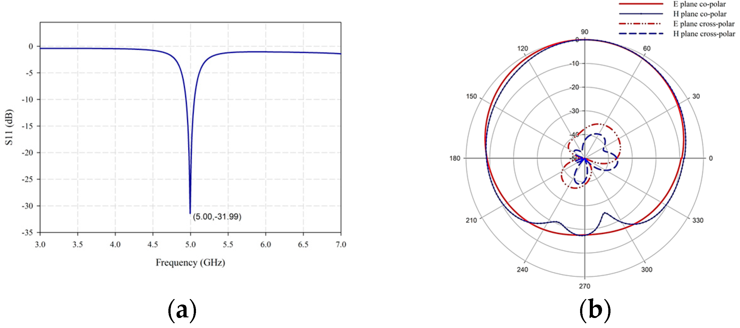
3. Principle of Operation

The geometrical parameters were calculated from the transmission line model approach [17]. The resonance frequency (fro) of the antenna in the undeformed state can be calculated from these parameters.
f r o = c 2 ε e f f L p + 2 Δ L c l
where c = Speed of light; ε e f f = Effective dielectric constant; Lp = Length of metallic patch; ΔLcl = Compensation length to accommodate fringing effect.
Δ L c l = 0.412 h ε e f f + 0.3 W p h + 0.264 ε e f f 0.258 W p h + 0.8
W p = c 2 f r o ε r + 1 2
Equation (1) can be rewritten as
f r o = c 2 ε e f f L e f f
where Leff = Effective length of the metallic patch.
The effective dielectric constant ( ε e f f ) is correlated to the dielectric constant of the substrate ( ε r ), the substrate thickness (h). and the width of the patch (Wp) as follows:
ε e f f = ε r + 1 2 + ε r 1   2 1 + 12 h W p
From Equations (3) and (4), the resonance frequency f r o is dependent on the effective length (Leff) and width (Wp) of the metallic patch of the antenna.

Antenna Under Tensile Load

Let us assume that a tensile load is applied to the antenna (Figure 3).
The antenna deformation (Δl) is calculated and added with effective length (Leff). Then, Equation (4) is rewritten as
f r ε = c 2 ε e f f L e f f + Δ l
                                                            = c 2 ε e f f L e f f 1 + Δ l L e f f
                                            = c 2 ε e f f L e f f 1 + ε l
f r ε                                 = f r 0 1 + ε l
f r ε                   = C f r 0
where f r ε is the resonance frequency of the antenna subjected to deformation.
Variation in the resonance frequency is calculated from Equation (9) and is approximately a linear relationship. The slope of the resonant frequency ( f r 0 ) of the patch antenna to the strain in the longitudinal direction ( ε l ) represents the sensitivity coefficient. Further, during tensile loading, the width (Wp) of the antenna is reduced by a factor of υ ε l W p considering Poisson’s effect:
Δ W                       = 1 ν ε l W p

4. Simulation of Tensile Test in HFSS

A uniformly distributed strain field is calculated across the patch antenna from basic standard methods to simulate the strain fields that would have occurred during the experimental phase. The strain values will be a function of Young’s Modulus, and the parameters considered for calculating strain values are tabulated in Table 2.
The strain ranges from 0 to 1.6% (0 to 16,000 με) at an increment step of 0.2% (2000 με) have been applied to the simulated model. This is accomplished by modifying the antenna geometry in HFSS by providing the change in length and width values calculated per Equation (13) and Equation (14), respectively. Subsequently, the resonance frequency analysis is conducted for the strain values mentioned in the above range. The strain range is selected from the stress–strain behaviour of the FR4 material [27].
ε l             = Δ L p L p
Δ L p       = ε l × L p
Δ W       = 1 ν ε l W p

5. Results and Discussion

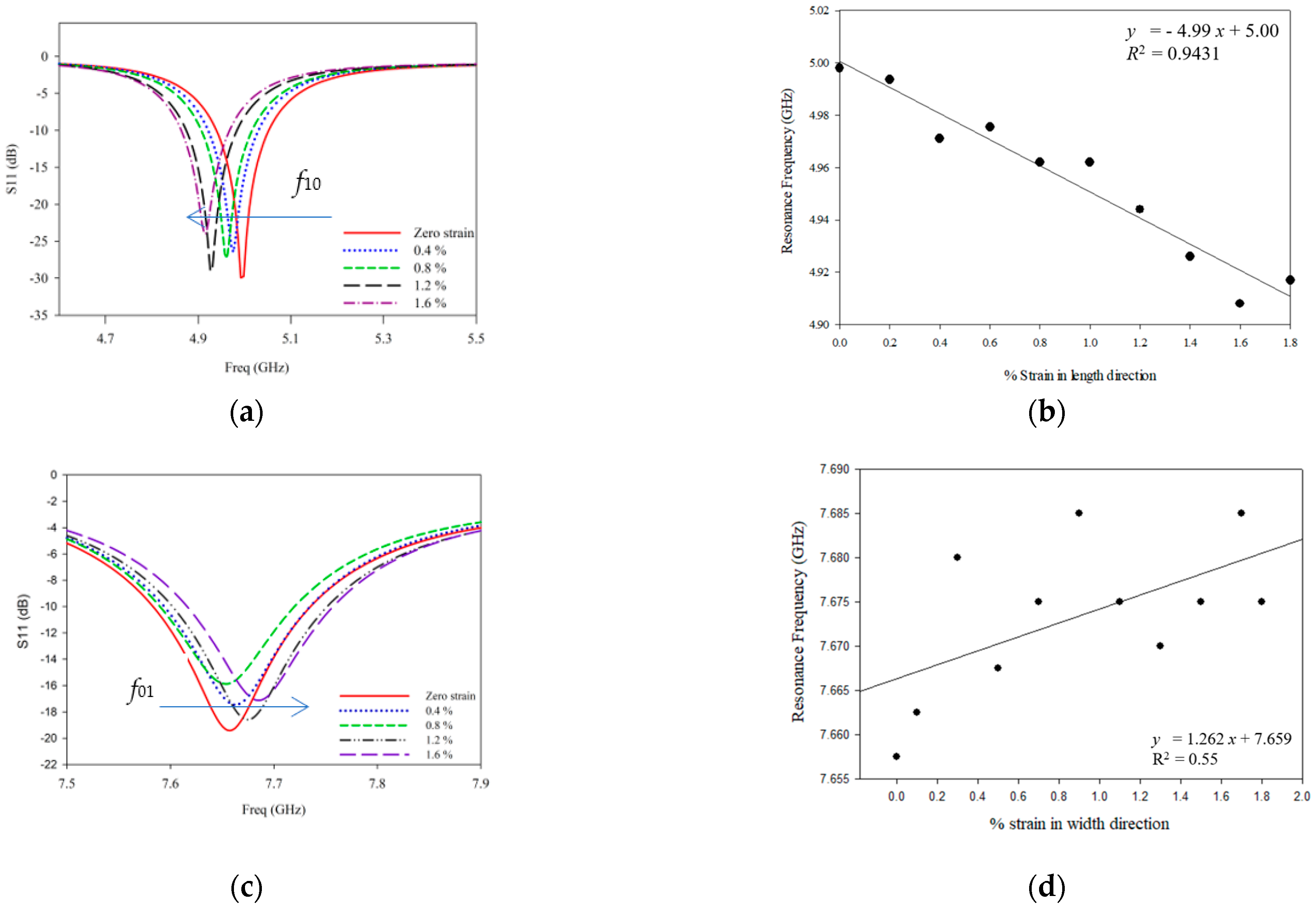
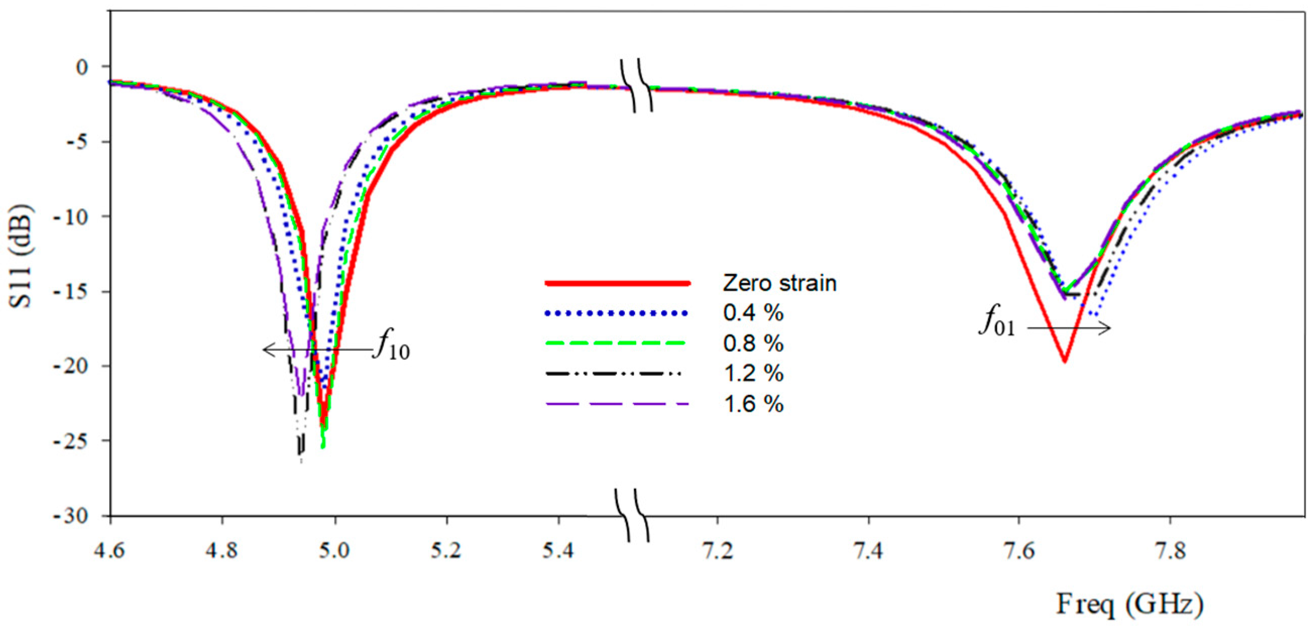
5.1. Strain Sensitivity of Antenna Sensor Subjected to Longitudinal and Transverse Deformations
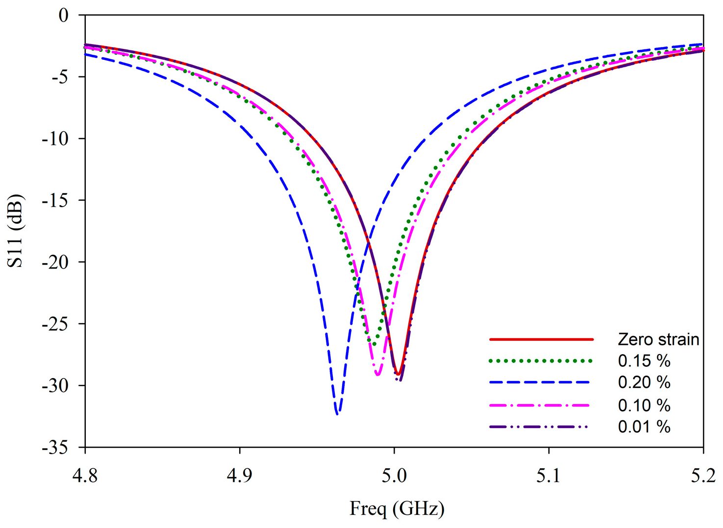
The resonance frequency variation corresponding to the longitudinal and transverse deformations is plotted in Figure 4a and 4c, respectively. As the tensile strain increases, the resonant frequency of the patch antenna shifts towards the lower side. The frequency values corresponding to Figure 4a against % strain are plotted in Figure 4b. A good correlation coefficient (R2) 0.9431 indicates a linear relationship for the resonant frequency variation in the patch antenna for longitudinal strains.
The fitted line’s slope, i.e., the strain sensor’s sensitivity coefficient, is −4.99 kHz/με, which means that the resonance frequency decreases by 4.99 kHz for every 1με increase within a range starting from 0.2% (2000 με) longitudinal strain. This aligns with the theoretical calculation of the resonance frequency shift, given by Equation (9). The relative error is less than 0.1%, which indicates that the effect of width in the first resonant frequency is negligible, which agrees with the studies mentioned by Wan et al. [23]. On the other hand, from Figure 4c, it is observed that the resonance frequency shifts towards the higher side for TM01 mode for transverse deformations. The sensitivity is 1.262 kHz/με with a linear fit of R2 = 0.55. These results indicate that changes in width considerably impact transverse strain sensing.
The effects of tensile loading along the longitudinal and transverse directions are co-simulated, and the frequency shifts are plotted in Figure 5 for better understanding. It is observed that for the given strain range (0 to 1.6%), the shift in resonance frequency (f10) provides longitudinal strain, and the other (f01) provides transverse strain. These results strongly recommend the ability of the proposed antenna sensor to sense longitudinal and transverse strains together from a single device.

5.2. Sensing Range

Another set of simulations was conducted for lower strain ranges to evaluate the sensor’s sensitivity in the lower strain region, i.e., <0.2% (<2000 με). The resonance frequency shift becomes non-linear for longitudinal strains lower than 1000 με, as shown in Figure 6.
The change in resonance frequency becomes stagnant below 100 με. Therefore, this specific patch antenna’s ability to sense strain is limited for strain values greater than 0.1% (1000 με). The changes in the dimensions of the patch antenna may directly influence antenna gain (Gp), which provides information regarding the radiation intensity. Moreover, antenna gain and aperture area are known to be directly correlated (Equation (14); the changes in the dimensions may impact the gain. It is observed that the antenna gain varies at a significantly lower tolerance of 2.81 ± 0.01 dB. These results shed light on the possibility of using a patch antenna as a sensor and a communication device.

5.3. Comparison with the Sensors Available in the Literature

The proposed sensor was compared with some of the major works reported in the literature (Table 3). To the best of the authors’ understanding, the effect of quarter-wave transformer fed patch antenna on bidirectional strain sensing is novel.

6. Conclusions

In this paper, we presented and numerically analyzed an edge-fed microstrip patch antenna strain sensor for SHM applications. The designed antenna resonates at 5 GHz and is capable of high data transfer with minimal interference. The tensile loading is simulated by providing longitudinal and transverse stains in regular steps. The antenna’s resonant frequency shifts towards the lower side in TM10 mode. The findings show that the suggested sensor demonstrates a sensitivity of −4.99 kHz/με within a longitudinal strain range of 2000 με (0.2%) to 16,000 με (1.6%). A linear relationship (R2 = 0.9431) is obtained for the sensor, aligned with the mathematical model. However, the frequency shift becomes stagnant below 100 με, and the linearity in sensing disappears below 1000 με. The effect of transverse strains on the strain sensing was also studied. It revealed that when the width reduces due to Poisson’s effect, the resonant frequency shifts toward the higher side in TM10 mode. This feature of the patch antenna sensor makes it more suitable for obtaining bidirectional surface strains from a single device.
Furthermore, the influence of antenna length and the impedance matching techniques in strain sensing were explored in detail. Impedance matching in the rectangular patch antenna is accomplished by a quarter-wave transformer, as previously explained in Section II(b). The quarter-wave transformer’s length changes as the patch antenna strains, altering the electrical length (βl) and the input impedance (Zin). This phenomenon enhances the frequency shift and becomes a prominent factor for sensing higher strains. It was also observed that the linear strain effects on the antenna gain are minimal. Moreover, the multi-physics methodology used in this paper can be adopted to analyze similar strain sensors for SHM applications in the future.

Author Contributions

Conceptualization: M.P.H. and S.K.M.; methodology: S.K.M., J.S.B. and M.P.H.; software: A.P.P.; validation: A.P.P., S.K.M. and M.P.H.; formal analysis: A.P.P.; investigation: A.P.P.; resources: S.K.M., data curation: A.P.P.; writing—original draft preparation: A.P.P.; writing—review and editing: S.K.M., J.S.B. and M.P.H.; visualization: A.P.P., supervision: J.S.B., S.K.M. and M.P.H.; project administration: J.S.B., S.K.M. and M.P.H. All authors have read and agreed to the published version of the manuscript.

Funding

This research received no external funding.

Institutional Review Board Statement

Not applicable.

Informed Consent Statement

Not applicable.

Data Availability Statement

The data presented in this study are available upon request from the corresponding author.

Acknowledgments

The authors are grateful to Amritandamayi Devi (Amma), Chancellor, Amrita Vishwa Vidyapeetham, for her unwavering support towards establishing interdisciplinary research and development. The author A.P. Praveen would like to thank CSIR-HRDG for the SRF-Direct award (File No: 09/0942(19189)/2024-EMR-I dated 16-07-2024).

Conflicts of Interest

The authors declare no conflicts of interest.

References

  1. Farrar, C.R.; Worden, K. An Introduction to Structural Health Monitoring. Philos. Trans. R. Soc. A Math. Phys. Eng. Sci. 2007, 365, 303–315. [Google Scholar] [CrossRef] [PubMed]
  2. Kot, P.; Muradov, M.; Gkantou, M.; Kamaris, G.S.; Hashim, K.; Yeboah, D. Recent Advancements in Non-Destructive Testing Techniques for Structural Health Monitoring. Appl. Sci. 2021, 11, 2750. [Google Scholar] [CrossRef]
  3. Keerthi, M.G.; Shenoy, A.D.; Devanarayanan, B.; Sharath, V.S.; Hariprasad, M.P. Design of Tabletop Automated Plane Polariscope for Digital Photoelastic Measurements; Springer Nature: Heidelberg, Germany, 2022; pp. 675–682. [Google Scholar]
  4. Bhandari, R. Case study of structural health monitoring in india and its benefits. J. Civ. Eng. Sci. Technol. 2020, 11, 1–7. [Google Scholar] [CrossRef]
  5. Ilyas Rather, A.; Motwani, P.; Laskar, A.; Banerjee, S.; Seng Lok, T.; Lalji Rai, G. Requirements of Indian Guidelines for Structural Health Monitoring. e-J. Nondestruct. Test. 2022, 26541. [Google Scholar]
  6. Benchirouf, A.; Kanoun, O.; Benchirouf, A.; Zichner, R.; Müller, C.; Kanoun, O. Electromagnetic Simulation of Flexible Strain Sensor Based Microstrip Patch Antenna. Int. J. Microw. Opt. Technol. 2015, 10, 397. [Google Scholar]
  7. Kumar, P.; Hariprasad, M.P.; Menon, A.; Ramesh, K. Experimental Study of Dry Stone Masonry Walls Using Digital Reflection Photoelasticity. Strain 2020, 56, e12372. [Google Scholar] [CrossRef]
  8. Harinath Reddy, C.; Mini, K.M.; Radhika, N. Structural Health Monitoring—An Integrated Approach for Vibration Analysis with Wireless Sensors to Steel Structure Using Image Processing; Springer Nature: Heidelberg, Germany, 2019; pp. 1595–1610. [Google Scholar]
  9. Nisha, M.S.; Venthan, S.M.; Rangasamy, G.; Sam, D.P.; Akilesh, G.; Bhaskar, D.S.; Kumar, N.H. Fabrication and Testing of RGO-PVDF Nano sensing Sheets on Glass Fibre-Reinforced Polymer for Structural Health Monitoring in Aerospace Engineering. Appl. Nanosci. 2023, 13, 5935–5947. [Google Scholar] [CrossRef]
  10. Chen, H.-P.; Ni, Y.-Q. Introduction to Structural Health Monitoring. In Structural Health Monitoring; Balageas, D., Fritzen, C.-P., Güemes, A., Eds.; ISTE Ltd.: London, UK, 2006; pp. 1–14. [Google Scholar]
  11. Zhang, B.; Lyu, Y.; Lee, Y. Passive Wireless Strain and Crack Sensing Using a RFID-Based Patch Antenna. J. Phys. Conf. Ser. 2022, 2198, 012018. [Google Scholar] [CrossRef]
  12. Tchafa, F.M.; Huang, H. Microstrip Patch Antenna for Simultaneous Strain and Temperature Sensing. Smart Mater. Struct. 2018, 27, 065019. [Google Scholar] [CrossRef]
  13. Tata, U.; Huang, H.; Deb, S.; Wang, J.; Chiao, J.-C. A Patch Antenna-Based Strain Sensor for Structural Health Monitoring. In Proceedings of the SPIE Smart Materials, Nano- and Micro-Smart Systems, Melbourne, Australia, 9–12 December 2008. [Google Scholar]
  14. Song, G.; Zhang, B.; Lyu, Y.; Wang, X.; Wu, B.; He, C.; Lee, Y.-C. Strain Omnidirectional Detection Based on Circular Patch Antenna. Sens. Actuators A Phys. 2020, 315, 112275. [Google Scholar] [CrossRef]
  15. Souri, H.; Banerjee, H.; Jusufi, A.; Radacsi, N.; Stokes, A.A.; Park, I.; Sitti, M.; Amjadi, M. Wearable and Stretchable Strain Sensors: Materials, Sensing Mechanisms, and Applications. Adv. Intell. Syst. 2020, 2, 2000039. [Google Scholar] [CrossRef]
  16. Sanders, J.W.; Yao, J.; Huang, H. Microstrip Patch Antenna Temperature Sensor. IEEE Sens. J. 2015, 15, 5312–5319. [Google Scholar] [CrossRef]
  17. Tata, U.; Huang, H.; Carter, R.L.; Chiao, J.C. Exploiting a Patch Antenna for Strain Measurements. Meas. Sci. Technol. 2009, 20, 015201. [Google Scholar] [CrossRef]
  18. Arango Toro, J.; Montes Granada, W.F.; Yepes Zuluaga, S.M. Design and Implementation of a Wearable Patch Antenna That Serves as a Longitudinal Strain Sensor. Text. Res. J. 2021, 91, 2795–2812. [Google Scholar] [CrossRef]
  19. Gregori, A.; Di Giampaolo, E.; Di Carlofelice, A.; Castoro, C. Presenting a New Wireless Strain Method for Structural Monitoring: Experimental Validation. J. Sens. 2019, 2019, 1–12. [Google Scholar] [CrossRef]
  20. Manekiya, M.; Donelli, M.; Kumar, A.; Menon, S.K. A Novel Detection Technique for a Chipless RFID System Using Quantile Regression. Electronics 2018, 7, 409. [Google Scholar] [CrossRef]
  21. Abdulhussein, A.M.; Khidhir, A.H.; Naser, A.A. 2.4 GHz Microstrip Patch Antenna for S-Band Wireless Communications. J. Phys. Conf. Ser. 2021, 2114, 012029. [Google Scholar] [CrossRef]
  22. Donelli, M.; Menon, S.; Kumar, A. Compact Antennas for Modern Communication Systems. Int. J. Antennas Propag. 2020, 2020, 1–2. [Google Scholar] [CrossRef]
  23. Nawaz, H.; Umar Niazi, A. Multi-Port Monostatic Antenna System with Improved Interport Isolation for 2.4GHz Full Duplex MIMO Applications. Electromagnetics 2020, 40, 424–434. [Google Scholar] [CrossRef]
  24. Wan, C.; Xie, L.; Xu, K.; Xue, S.; Jiang, C.; Wan, G.; Ding, T. Transverse Deformation Effect on Sensitivity of Strain-Sensing Patch Antenna. Int. J. Distrib. Sens. Netw. 2020, 16, 155014772090819. [Google Scholar] [CrossRef]
  25. Mohammed, A.S.B.; Kamal, S.; Ullah, U.; Mohammed, A.S.; Ahmad, Z.A.; Othman, M.; Hussin, R.; Fariz, M.; Rahman, A. Microstrip Patch Antenna: A Review and the Current State of the Art. J. Adv. Res. Dyn. Control Syst. 2019, 11, 510–524. [Google Scholar]
  26. Parchin, N.O. Editorial on “Design, Analysis, and Measurement of Antennas”. Appl. Sci. 2023, 13, 10069. [Google Scholar] [CrossRef]
  27. Ossa-Molina, O.; Duque-Giraldo, J.; Reyes-Vera, E. Strain Sensor Based on Rectangular Microstrip Antenna: Numerical Methodologies and Experimental Validation. IEEE Sens. J. 2021, 21, 22908–22917. [Google Scholar] [CrossRef]
  28. Herbko, M.; Lopato, P. Microstrip Patch Strain Sensor Miniaturization Using Sierpinski Curve Fractal Geometry. Sensors 2019, 19, 3989. [Google Scholar] [CrossRef] [PubMed]
  29. Azam, S.A.; Fragoso, A. Experimental and Numerical Simulation Study of the Vibration Properties of Thin Copper Films Bonded to FR4 Composite. Appl. Sci. 2020, 10, 5197. [Google Scholar] [CrossRef]
  30. Sharma, S.; Tripathi, C.C.; Rishi, R. Impedance Matching Techniques for Microstrip Patch Antenna. Indian J. Sci. Technol. 2017, 10, 1–16. [Google Scholar] [CrossRef]
Figure 1. Design parameters of antenna.
Engproc 93 00008 g001
Figure 2. (a) Reflection characteristics of antenna at 5 GHz. (b) Radiation characteristics of antenna at 5 GHz.
Engproc 93 00008 g002
Figure 3. Patch antenna sensor subjected to tensile load.
Engproc 93 00008 g003
Figure 4. (a) Frequency shift corresponds to the longitudinal deformation in TM10 mode. (b) Longitudinal strain sensitivity. (c) Frequency shift corresponds to the transverse deformation in TM01 mode. (d) Transverse strain sensitivity.
Engproc 93 00008 g004
Figure 5. The resonant frequency shift in the microstrip antenna subjected to tensile strain (TM10 and TM01 mode).
Engproc 93 00008 g005
Figure 6. Resonance frequency shift for strains less than 2000 με.
Engproc 93 00008 g006
Table 1. Dimensions of patch antenna sensor.
ParametersDescriptionDimensions (mm)
LsSubstrate length60
WsSubstrate width30
hSubstrate thickness0.8
LpLength of metallic patch13.43
WpWidth of metallic patch17.7
LfLength of feedline13.31
WfWidth of feedline1.52
QLLength of quarter-wave transformer8.43
QWWidth of quarter-wave transformer0.34
Table 2. Properties of FR4 substrate for strain calculations.
Dielectric constantεr4.4
Modulus of elasticity (GPa)E20.4
Poisson’s ratioυ (LW)0.12
Length of metallic patchLp13.43
Loss tangenttan δ0.02
Cross sectional area (mm2)A (mm2)24
Table 3. Comparison with major works in the literature.
Sl NoRefFrequency of Operation (GHz)StructureSubstrateType of LoadingSensitivityBidirectional Strain Sensing CapabilityRange
1[17]14.9/19.6Rectangular patchFlexible polyimide film (Kapton HN)Bending−16.4 kHz/µεYes0 to 0.5%
2[18]2.45RectangularCotton fabric as a dielectric and conductors made of flexible copper sheetsTensile2.38 MHz/µεNo-
3[24]2.45Rectangular patch with short circuited viasRT-5880Tensile−1.730 kHz/µεYes
(0.640 kHz/µε)
0 to1.6%
4[27]2.45Rectangular microstripFR4Tensile−2.847 kHz/µεNo0 to 0.4%
5Our work5Rectangular microstripFR4Tensile−4.99 kHz/μεYes
(1.262 kHz/με)
0.2% to 1.6%
Disclaimer/Publisher’s Note: The statements, opinions and data contained in all publications are solely those of the individual author(s) and contributor(s) and not of MDPI and/or the editor(s). MDPI and/or the editor(s) disclaim responsibility for any injury to people or property resulting from any ideas, methods, instructions or products referred to in the content.

