1. Introduction
Temperature measurement is crucial in production processes, environmental protection, and safety protection. Heat sensors are generally divided into three types: intrusive, semi-intrusive, and non-intrusive. Invasive temperature sensors are installed either on or next to a component and involve a cable to connect the sensors to the measuring instrument. Due to their simplicity and low cost, thermocouples are widely used in multiple applications. However, they have weak and noise-sensitive output signals and expensive cables, which limit their applications. In addition to high costs related to installation and maintenance, another disadvantage of these cabling systems is the difficulty of measuring temperature in moving or heavy areas. Patch antennas have been introduced as thermal sensors recently. These sensors are lightweight and small with high sensitivity and wide bandwidth [
1]. Non-invasive sensors are usually based on infrared thermometers, interferometers, and luminescence; they can measure the temperature of an environment remotely without physical contact, though their price is often high. Semi-invasive sensors were placed at the point of interest, but temperature readings were taken far away. Such temperature sensors have garnered attention recently since the implementation of such a system can be substantially lower than that of an invasive or non-invasive temperature sensing system [
2]. To maintain standards, all airlines seeking SHM systems must improve the safety of the aircraft, lower the maintenance costs and frequency, and extend the operation of the aircraft. SHM systems can also be used for static monitoring applications such as long-distance transmission lines, cultural heritage monitoring, and modern wooden model home maintenance. [
3,
4].
The use of patch antennas for various applications has been demonstrated. They can be used for strain measurements [
5], as crossovers in beamforming applications [
6,
7], and in multiple-input/multiple-output (MIMO) systems [
8], to mention a few. When temperature is applied to a patch antenna, it changes its shape and current distribution, causing the resonant frequency to change [
9]. Recently, a patch antenna has been used together with an IoT platform as a temperature sensor [
10]. Using PEDOT: PSS-based chipless printed loop antenna for temperature sensing applications is presented [
11]. The impact of antenna shape on sensor performance has also been investigated by researchers [
12]. A dual-band antenna for temperature sensing has been reported by Dong, Helei et al. recently [
13]. A simple and easy method for realizing a high-sensitivity, fast-response microstrip temperature sensor using a passive RFID antenna has been demonstrated [
14]. In this work, a rectangular patch antenna is subjected to thermal load, and its influence on the resonance characteristics is studied in detail.
2. Design of Patch Antenna
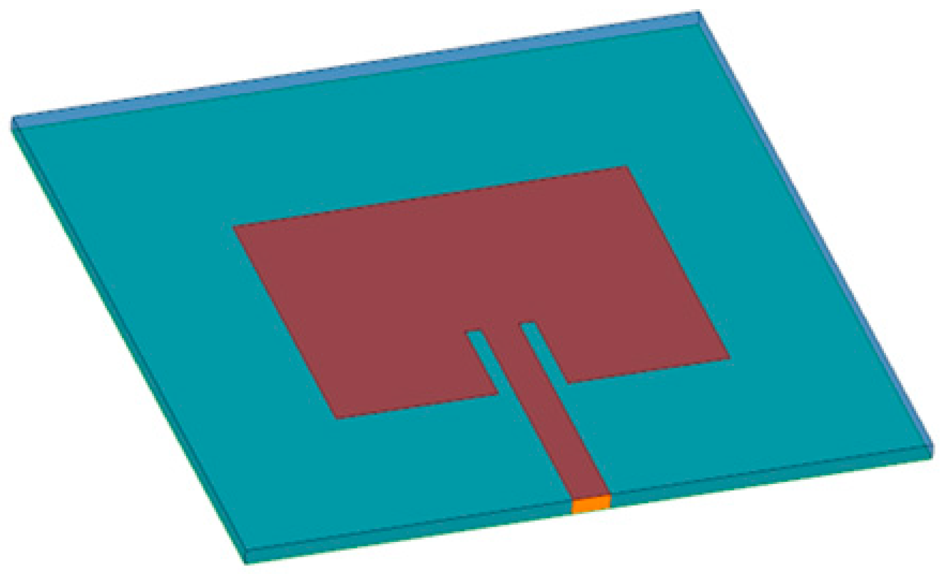
The rectangular patch antenna, depicted in
Figure 1, is vital in wireless communication systems, especially when repurposed as a temperature sensor, as explored in this study. Carefully chosen dimensions, such as length (L) and width (W), are tailored to meet desired specifications like resonant frequency and bandwidth, while also enabling accurate temperature sensing. Employing an FR4 substrate, having a dielectric constant (εᵣ) of 4.4 and a thickness (h) of 1.6mm, significantly influences the antenna’s performance. The paper aims to explain the design details of a patch antenna for temperature sensing purposes, providing insights into geometric considerations and material properties for optimal performance in this specific role.
The design process of an inset-fed rectangular patch antenna targets a resonant frequency of 2.45 GHz, which involves comprehensive simulations using ANSYS HFSS.
Table 1 outlines the specific design dimensions critical to achieving the desired resonance. Simulation assessments are conducted across a frequency spectrum ranging from 2 GHz to 4 GHz to evaluate the antenna’s performance. Upon simulation, the fundamental frequency of the unaltered rectangular patch antenna is determined to be 2.4413 GHz, aligning closely with the intended operational frequency. This resonance frequency validation underscores the effectiveness of the antenna’s design parameters in facilitating optimal performance within the designated frequency band.
3. Principle of Operation
A metallic ground plane, a dielectric substrate, and a metallic radiation patch form a microstrip patch antenna. An electromagnetic resonator consists of a ground plane and an electromagnetic field, which is the electric field of the resonant frequency. The transmission line model states that the antenna resonant frequency,
f, can be written as:
where ε
r = dielectric constant of the substrate,
c = speed of light, and l
e = electrical length of the patch.
The patch antenna’s resonance frequency is highly sensitive to changes in the dielectric constant of the substrate materials. As the temperature fluctuates, the dielectric constant changes, altering the antenna’s resonance frequency. As a result, temperature-induced alterations in resonant frequency have an impact on the patch antenna’s impedance. This fluctuation in impedance may be monitored and associated with temperature variations, making the patch antenna a useful thermal sensor. However, calibration is essential for precise temperature measurement. Calibration is the process of characterizing the link between temperature variations and changes in antenna properties, such as resonant frequency or impedance.
4. Calculation of Change in Length
The electromagnetic resonator is constructed between the ground layer and the electromagnetic resonator two types TM010 and TM100 at the resonance frequency, ensuring their flow throughout the field’s length and width, respectively. When calculating particularly the TM010, we are measuring only the length of the microstrip antenna. When the antenna is subjected to temperature, the length and width of the patch become deformed, and therefore the resonant frequency will be shifted. The resonant frequency variation can be calculated by:
ΔL: Change in length (meters)
α: Coefficient of thermal expansion (meter/meter/°C)
L: Original length of the antenna (meters)
ΔT: Change in temperature (°C)
Resonant frequency changes in the antenna can be represented by changes in dielectric constant variation in the substrate and length of the radiating element of the patch.
By substituting Equations (4) and (5) into Equation (2) and normalizing frequency shifts with the resonant frequency, the normalized frequency change
is directly proportional to the change in electrical length.
Deformation due to thermal loading is approximated to the thermal expansion of the patch antenna and can be determined from the coefficient of thermal expansion (α).
The normalized frequency change and the temperature change can be expressed as
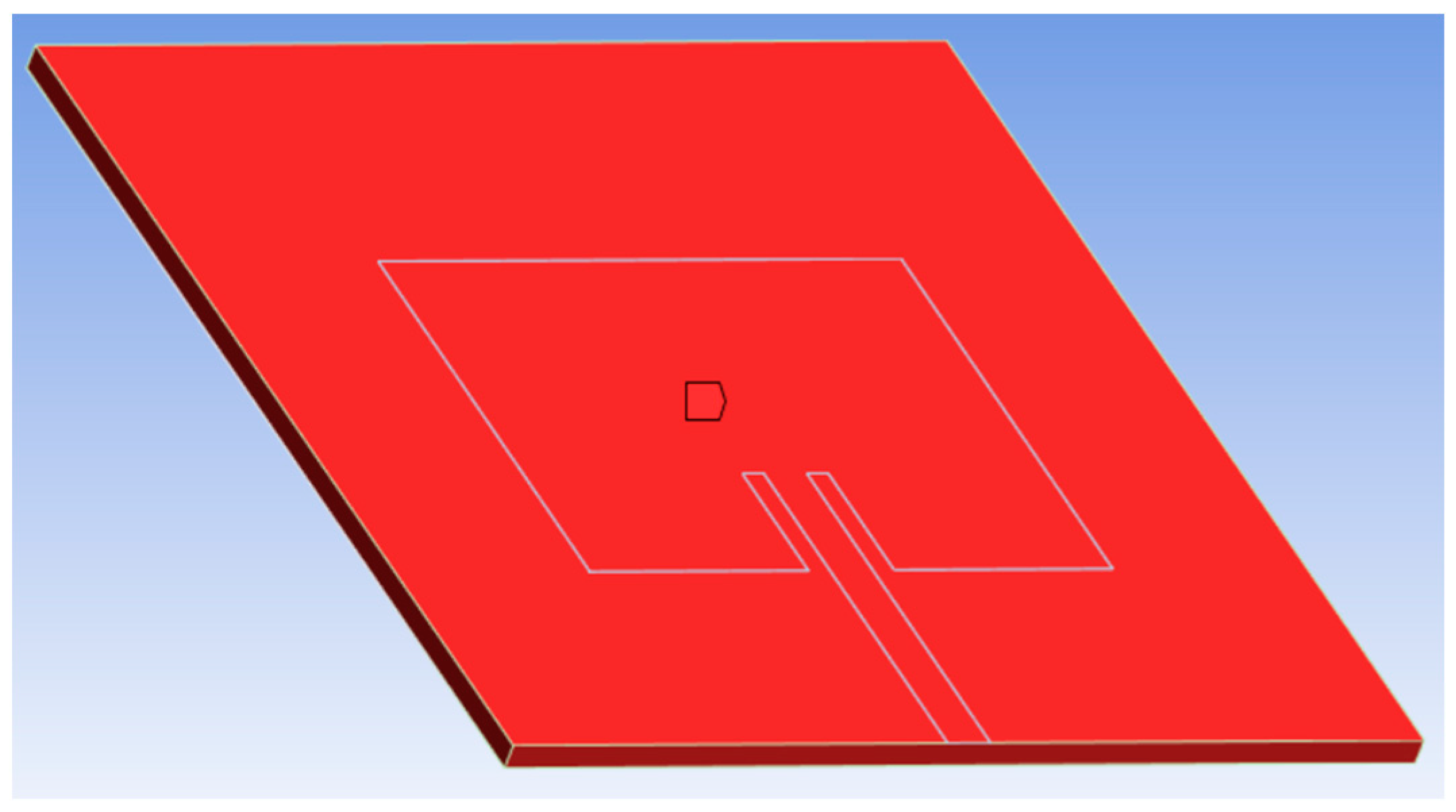
Thermal stress arises from the restriction imposed on a material’s expansion or contraction by its surroundings. When a material experiences heating or cooling, it expands or contracts correspondingly. However, external constraints may hinder this free expansion or contraction process. Consequently, thermal stresses build up within the material, potentially resulting in changes in length, as demonstrated in
Figure 2.
5. Results and Discussion
This study investigated the impact of temperature variations on the resonant frequency of a 2.4 GHz patch antenna. Simulations were conducted using Ansys Workbench software to analyze the relationship between temperature-induced dimensional changes and the resulting shifts in resonant frequency.
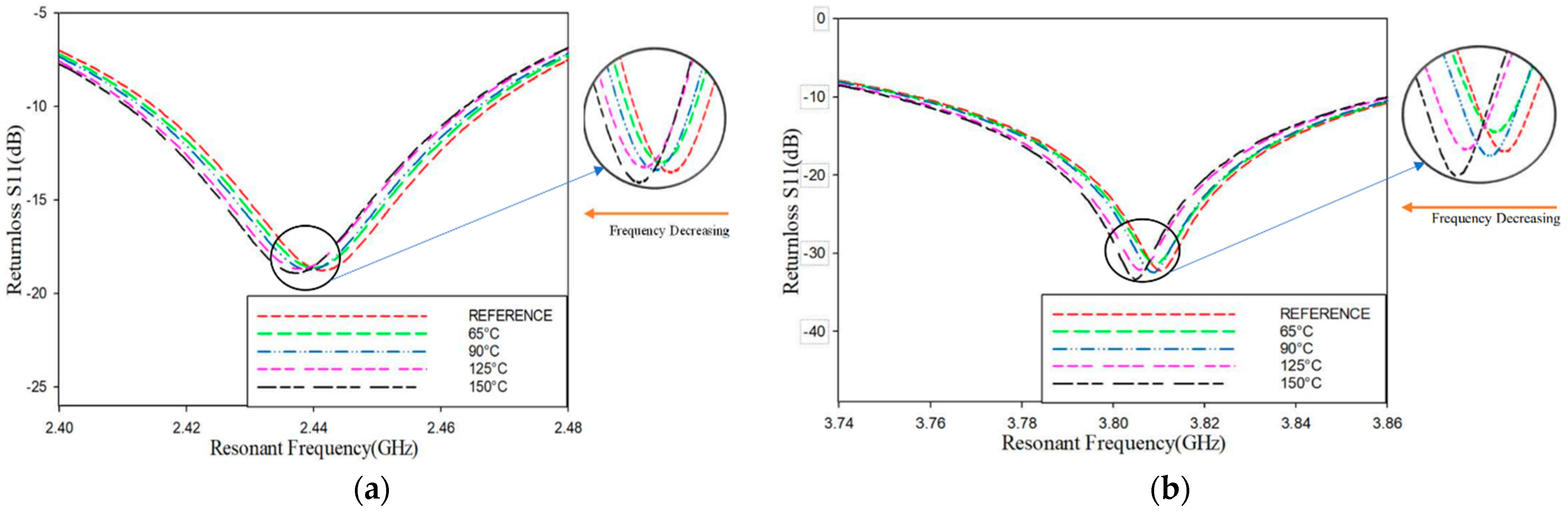
As the temperature surrounding the patch antenna increased from 30 °C to 150 °C, the resonant frequency exhibited a trend in decrease at both 2.4 GHz and 3.8 GHz.
Figure 3a,b illustrate the return loss of the patch antenna, highlighting the shift in response to frequency changes caused by temperature fluctuations. Specifically, the frequency shift at 2.44 GHz primarily reflected changes in the length (ΔL) of the patch, whereas the shift at 3.81 GHz predominantly corresponded to changes in the width (ΔW).
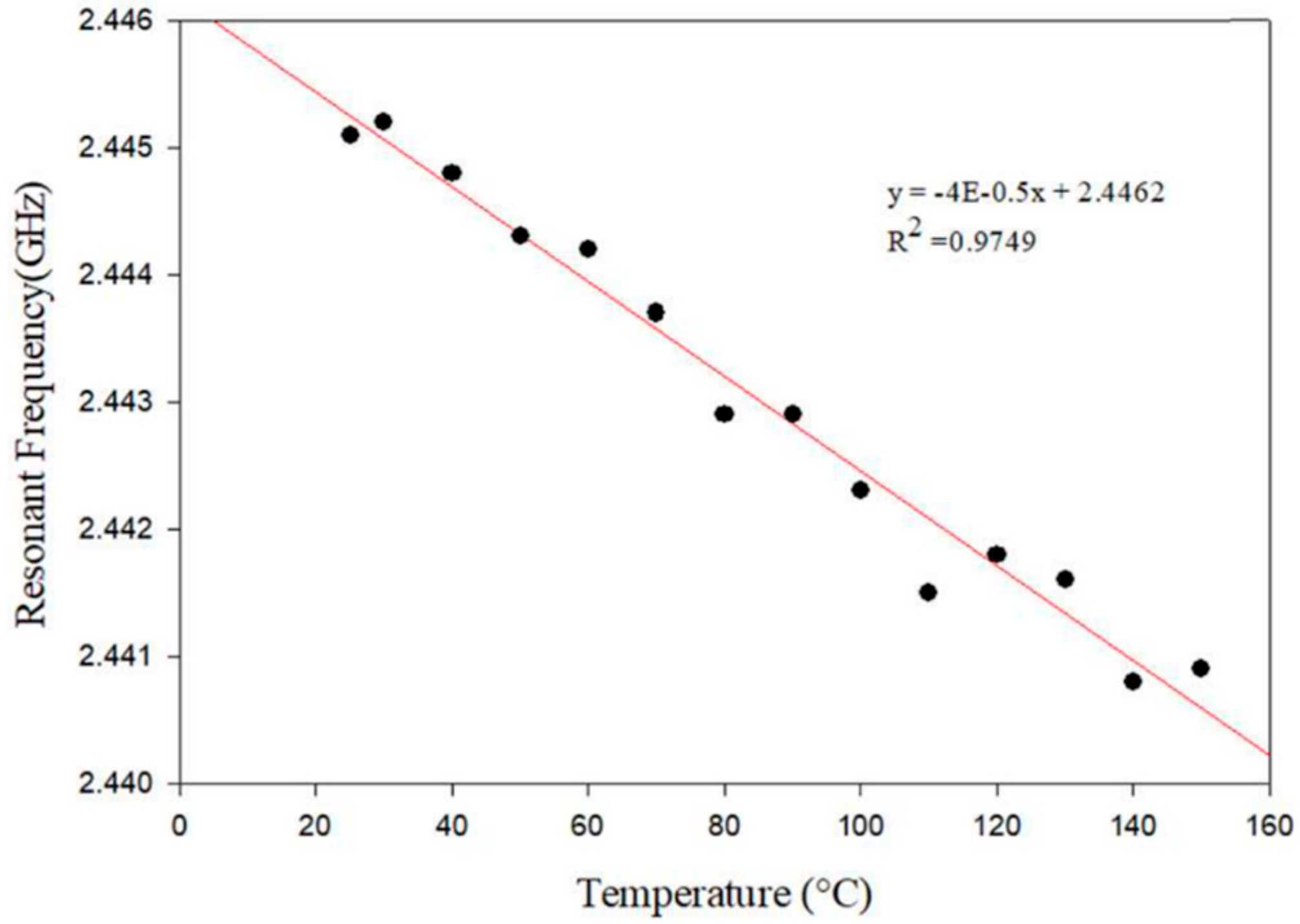
The graph
Figure 4 illustrates a negative correlation between temperature and frequency at 2.4 GHz. As temperature increases, the frequency decreases, indicating a clear relationship between temperature variations and frequency shifts. The measured 2.4 GHz frequency reflects variations caused by changes in the antenna’s width dimension. It is noteworthy that the data presented in the graph encompasses a limited temperature range, spanning from 30 °C to 150 °C, corresponding to a frequency range of 2.4406 GHz to 2.4364 GHz. Within this range, sensitivity can be calculated as the change in frequency per unit degree Celsius, which came to be 0.4 MHz. Additionally, the graph allows for the determination of the correlation coefficient (R), which is 0.9749 at 2.4 GHz.
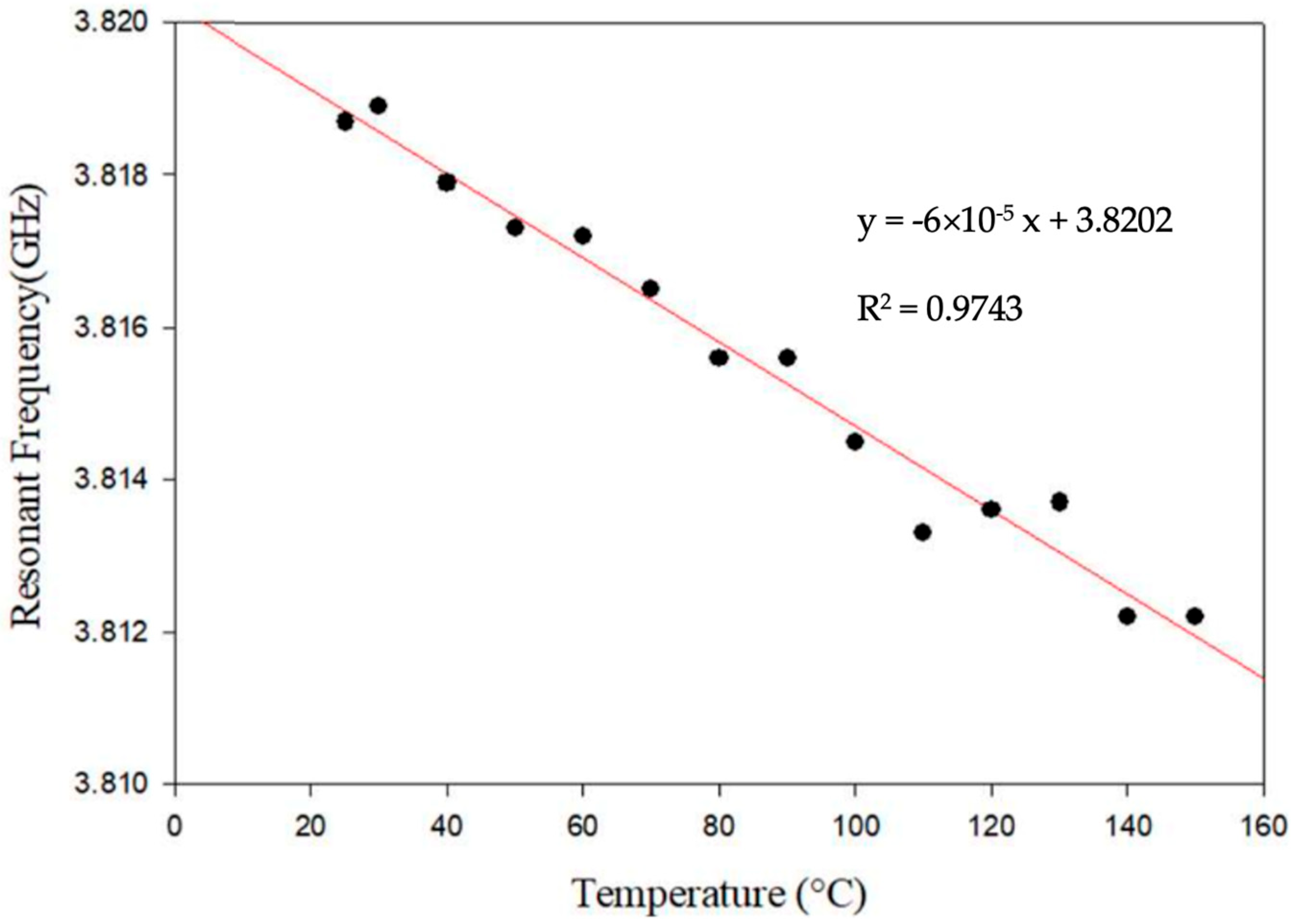
Similarly to the observations in
Figure 4,
Figure 5 also demonstrates a negative correlation between temperature and frequency at 3.8 GHz. The measured 3.8 GHz frequency reflects variations attributed to changes in the antenna’s length dimension. It is pertinent to note that the data presented in the graph are confined to a limited temperature range, spanning from 30 °C to 150 °C, corresponding to a frequency range of 3.8042 GHz to 3.8107 GHz. Within this range, sensitivity can be calculated as the change in frequency per unit degree Celsius, computed as 0.6 MHz. Moreover, the graph facilitates the determination of the correlation coefficient (R), which registers at 0.9743 at 3.8 GHz.
The findings highlight the proposed antenna’s potential as a sensitive thermal sensor, with the ability to detect temperature changes through frequency shifts. Moreover, the calculated sensitivities and correlation coefficients further validate the reliability and effectiveness of the sensor for temperature monitoring applications.
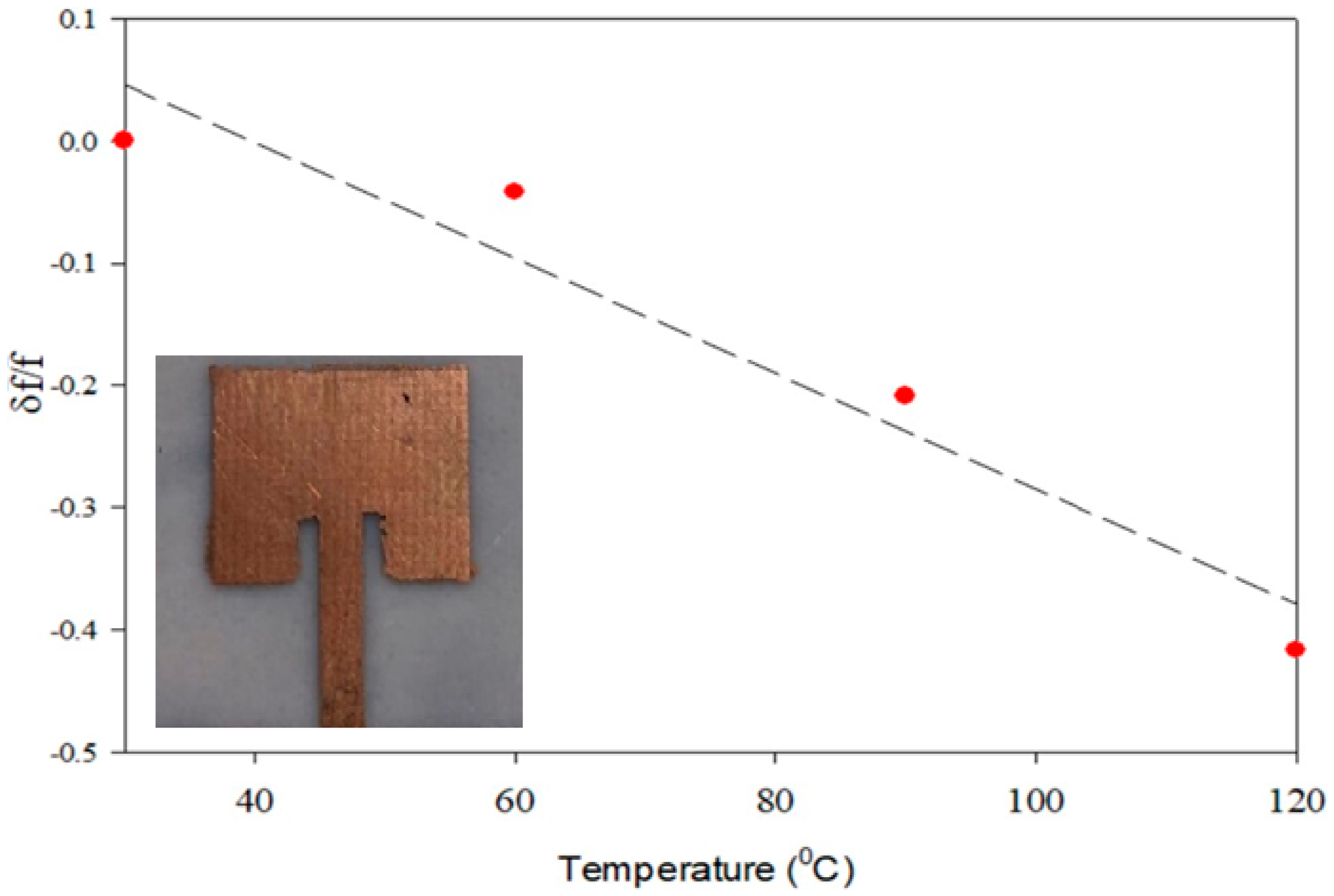
An RMSA is fabricated and tested in a controlled environment in a heat chamber from 30 °C to 120 °C. The results obtained are presented in
Figure 6.
The same analysis is carried out over the width of the patch. The first resonance of the patch shows a sensitivity of 0.04 MHz/°C and the second resonance shows a sensitivity of 0.06 MHz/°C. This provides an R2 = 0.932 from the experiment during the first resonance characterization. The results obtained experimentally are in good agreement with the simulated ones.
6. Conclusions
This paper explores the utilization of Rectangular Microstrip Antennas (RMSAs) as effective sensors for monitoring temperature changes in structures, focusing on structural health monitoring. The core principle revolves around the frequency shift in a patch antenna in response to shape variations caused by temperature changes. The design entails crafting an RMSA sensor on an FR-4 substrate specifically engineered to operate at 2.4 GHz, with simulations indicating that thermal-induced structural changes directly influence the antenna’s reflection parameters.
The sensing principle depends on the observation that the frequency of the patch antenna changes in accordance with the thermal expansion, offering a direct correlation between frequency variation and the degree of thermal loading and potential structural deformations. This insight presents a non-invasive method for tracking temperature fluctuations in structures wirelessly, thus potentially obviating the need for wired sensors in various scenarios. The applications of this technique span diverse domains, such as buildings, bridges, aircraft, and other structures, where temperature variations pose significant concerns for structural integrity.
Furthermore, the paper emphasizes the cost-effectiveness and simplicity of the RMSA approach for temperature sensing, suggesting its viability as a practical solution for widespread implementation in structural health monitoring. By demonstrating the efficacy of patch antennas as thermal sensors, this work paves the way for innovative avenues in the realm of structural health assessment, promising exciting possibilities for future applications and advancements in monitoring techniques.
Author Contributions
Conceptualization, S.K.M. and M.P.H.; methodology, S.K.M. and M.P.H.; software, B.V., D.D.R. and M.S.N.; validation, S.K.M. and M.P.H.; formal analysis, B.V., D.D.R. and M.S.N.; investigation, B.V., D.D.R. and M.S.N.; resources, S.K.M. and M.P.H.; supervision, S.K.M. and M.P.H.; project administration, S.K.M. and M.P.H. All authors have read and agreed to the published version of the manuscript.
Funding
This research received no external funding.
Institutional Review Board Statement
Not applicable.
Informed Consent Statement
Not applicable.
Data Availability Statement
Data sharing is not applicable.
Conflicts of Interest
The authors declare no conflicts of interest.
References
- Sanders, J.W.; Yao, J.; Huang, H. Microstrip patch antenna temperature sensor. IEEE Sens. J. 2015, 15, 5312–5319. [Google Scholar] [CrossRef]
- Tchafa, F.M.; Huang, H. Microstrip patch antenna for simultaneous strain and temperature sensing. Smart Mater. Struct. 2018, 27, 065019. [Google Scholar] [CrossRef]
- Chen, Z.; Zhou, X.; Wang, X.; Dong, L.; Qian, Y. Deployment of a smart structural health monitoring system for long-span arch bridges: A review and a case study. Sensors 2017, 17, 2151. [Google Scholar] [CrossRef] [PubMed]
- Pantoli, L.; Muttillo, M.; Ferri, G.; Stornelli, V.; Alaggio, R.; Vettori, D.; Chinzari, F. Electronic system for structural and environmental building monitoring. In Convegno Nazionale Sensori; Springer: Cham, Switzerland, 2018; Volume 539, pp. 481–488. [Google Scholar]
- Tata, U.; Huang, H.; Carter, R.L.; Chiao, J.C. Exploiting a patch antenna for strain measurements. Meas. Sci. Technol. 2009, 20, 015201. [Google Scholar] [CrossRef]
- Jayakrishnan, V.M.; Menon, S.K. Modified circular patch antenna-based crossover for beamforming applications. In Proceedings of the 2016 International Conference on Electrical, Electronics, and Optimization Techniques (ICEEOT), Chennai, India, 3–5 March 2016; IEEE: Piscataway, NJ, USA, 2016. [Google Scholar]
- Menon, S.K. Microstrip patch antenna assisted compact dual band planar crossover. Electronics 2017, 6, 74. [Google Scholar] [CrossRef]
- Muraleedharan, M.; Menon, S.K. Isolation enhancement of two element array using microstrip resonator. In Proceedings of the 2019 3rd International Conference on Trends in Electronics and Informatics (ICOEI), Tirunelveli, India, 23–25 April 2019; IEEE: Piscataway, NJ, USA, 2019. [Google Scholar]
- Yadav, R.K.; Kishor, J.; Yadava, R.L. Effects of temperature variations on microstrip antenna. Int. J. Netw. Commun. 2013, 3, 21–24. [Google Scholar]
- Satam, V.; Kulkarni, C.; Kholapure, A. Microstrip Antenna as a Temperature Sensor for IoT Applications. In Proceedings of the IEEE Microwaves, Antennas, and Propagation Conference (MAPCON), Bangalore, India, 12–16 December 2022. [Google Scholar]
- Bhattacharjee, M.; Nikbakhtnasrabadi, F.; Dahiya, R. Printed Chipless Antenna as Flexible Temperature Sensor. IEEE Internet Things J. 2021, 8, 5101–5110. [Google Scholar] [CrossRef]
- Azahra, T.; Liao, Y.-T.; Chen, Y.-C.; Kuo, C.-C. Analysis of the Influence of Patch Antenna Shapes for Wireless Passive Temperature Sensor Applications. Appl. Sci. 2025, 15, 3136. [Google Scholar] [CrossRef]
- Dong, H.; Zhen, C.; Li, X.; Pang, J.; Niu, Y.; Tan, Q.; Xiong, J.; Liu, T. Design and Testing of Miniaturized Dual-Band Microstrip Antenna Sensor for Wireless Monitoring of High Temperatures. IEEE Sens. J. 2023, 23, 27242–27250. [Google Scholar] [CrossRef]
- Miao, F.; Tian, P.; Tao, B.; Zang, Y. Passive RFID microstrip antenna sensor for temperature monitoring. Vacuum 2022, 201, 111108. [Google Scholar] [CrossRef]
| Disclaimer/Publisher’s Note: The statements, opinions and data contained in all publications are solely those of the individual author(s) and contributor(s) and not of MDPI and/or the editor(s). MDPI and/or the editor(s) disclaim responsibility for any injury to people or property resulting from any ideas, methods, instructions or products referred to in the content. |
© 2025 by the authors. Licensee MDPI, Basel, Switzerland. This article is an open access article distributed under the terms and conditions of the Creative Commons Attribution (CC BY) license (https://creativecommons.org/licenses/by/4.0/).


 and
and 
