Abstract
Due to the high demand for fuel efficiency, electric vehicles have come into the picture, as they only use batteries to power the vehicle. This requires constant charging of the batteries at charging stations, which are costly and impractical to install. But it is possible to install charging stations by making use of photovoltaic (PV) cells and demagnetization currents to self-charge batteries under stand-still conditions. The design of a bidirectional converter with asymmetrical half-bridge converter based on a switched reluctance motor (SRM) drive, using PV for electric vehicles, is implemented in this paper. It consists of developing a control unit (GCU), Li-ion battery pack, and photovoltaic (PV) solar cells that are integrated with a bidirectional converter and asymmetrical half-bridge converter (AHBC) to provide power to the SRM drive. The solar-assisted SRM drive can be operated in either the motoring mode or charging mode. In the motoring-mode GCU, the battery or PV energy can be used in any combination to power the SRM. In the charging-mode PV, the GCU and AC grids are used to charge the battery under stand-still conditions. This work helps in the self-charging of batteries using either the GCU or PV cells, as well as aids in the improvement in the performance characteristics. Also, this work compares the performance metrics for the proposed system and conventional system. The performance of the drive system using PV cells/GCU is evaluated and verified through MatLab/Simulink and experimental results.
1. Introduction
Electric vehicles (EVs) are receiving more attention today due to the demand for petroleum. Instead of an internal combustion engine, EVs have an electric motor. A permanent magnet synchronous motor (PMSM) is utilized in EVs, as they have high torque density and high efficiency, but they need power magnets, which are costly and have poor stability. Due to these drawbacks, the development of a rare-earth-free motor for EVs is being pursued [1,2]. One type of rare-earth-free motor is the SRM. This motor is used significantly in EVs, which have no permanent magnets and rotor windings. SRMs have high reliability and a robust structure, low cost, and good fault-tolerance ability.
In a battery-powered SRM drive, a DC/DC converter is employed to enhance the speed of responses and stabilize the DC voltages. However, using the SRM drive in the battery-powered mode limits the feasible driving distance due to the current battery technology’s limitations. To address this issue, photovoltaic (PV) cells are incorporated to facilitate battery charging, and during the driving mode, they support the main power source. However, by using a PV-integrated converter with an SRM drive, the topology of the bidirectional multiport is not achieved, and all three phases of the SRM share only one chopping switch, which leads to complex controls and poor fault tolerance [3].
A bidirectional, AHBC-based SRM drive using PV for an EV application to achieve flexible self-charging, multisource operation, and improved performance while motoring is the focus of this work. A PV circuit is integrated with the battery and a bidirectional converter to combine the AHBC for integrated functioning. For extending the driving range, PV panels are used, which lowers the dependency on charging stations. During braking, the energy is recovered and stored back in the battery. Under stand-still conditions, the batteries are rapidly charged using AC grids and PV panels, which also decreases dependency on charging stations. The performance of the drive system using PV cells/GCU is evaluated and verified through MatLab/Simulink (version 2018b) and the experimental results.
2. Detailed Study of a PV-Powered SRMD for EVs
A block diagram of the SRM drive for an electric vehicle powered by photovoltaic (PV) cells is depicted in Figure 1. The design of a multiport bidirectional SRM drive for EVs is proposed in this work. It consists of a PV array, bidirectional converter, battery, asymmetrical half-bridge converter, generating control unit (GCU) and SRM. To provide power to the SRM drive, the GCU, Li-ion battery pack, and PV solar cells are combined. This also helps in the self-charging of the battery either using the GCU or PV cells. The batteries require constant charging, as they are used to power the EV, and the charging stations are costly and impractical to install. This is now made possible by making use of PV cells and demagnetization of the current to self-charge the battery under stand-still conditions. It also helps to improve the performance characteristics (fault tolerance). A PV-powered SRM drive for EV is developed to obtain a flexible self-charging function, achieve multisource operation, and improve the motoring performance. In the PV-based SRMD’s operations, when a phase is turned on, phase winding is applied by a (+) DC-link voltage, which works in the excitation mode, and when the phase is turned off, a (−) DC-link voltage is applied to the phase winding, which works in the braking mode.
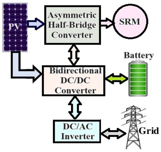
Figure 1.
PV-powered SRM drive.
Detailed information about the PV array, bidirectional converter with battery, asymmetrical half-bridge converter, and GCU are discussed, which are the main components in this work.
2.1. PV Array with MPPT Modeling
The equivalent circuit with the basic equations of the PV array and its characteristics are described in [4]. Here, a PV array of 213 W is sized for 2500 W (4 × 3) for the insolation (G) of 1000 W/m2, with a temperature (T) of 25 °C. Table 1 lists the PV array’s specifications.

Table 1.
PV array’s specifications.
The PV array’s obtained characteristics are depicted in Figure 2.
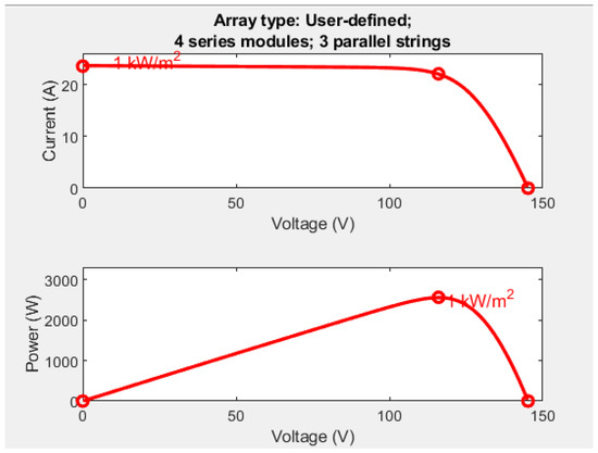
Figure 2.
Characteristics of the obtained PV array.
Maximum power point tracking (MPPT) is used to optimize the efficiency of the PV arrays, which typically have low conversion rates. The perturb and observe (P&O) method stands out as an ideal algorithm for medium-sized applications due to its simplicity. The P&O algorithm is simple, and it is discussed in [5]. It is observed from the flowchart that the MPP is calculated by incrementing or decrementing Vref according to the change in sign of the current, and based on that, the MPPT algorithm is coded as shown in Figure 3.
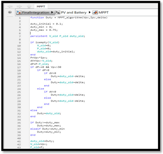
Figure 3.
MPPT code.
2.2. Configuration of Bidirectional DC-DC Converter (BDC) with Battery
BDC is widely used in applications such as UPS, fuel-cell hybrid power systems, hybrid EV energy systems, battery chargers, and PV hybrid power systems. Here, a BDC is used for a renewable energy system to store energy. The circuit diagram of the BDC and its design equations are described in [6], and it consists of two switches, S1 and S2, each.
In this work, the BDC with the battery has two operations (i.e., in PV and in GCU). Figure 4a shows a model of the PV array integrated with the BDC with the battery. The PV array is integrated with the BDC and fed to battery, which stores energy. Via the AC grids/GCU, the battery can be charged when the PV power is inadequate, which substantially reduces the dependency on charging stations without external charging converters. Figure 4b depicts the model of the BDC with the battery in the GCU.
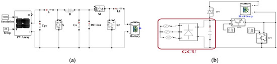
Figure 4.
Model of the BDC: (a) battery with PV; (b) battery with GCU.
2.3. Configuration of the AHBC-Fed SRM
A 3ɸ-AHBC was used in this work and the structure is explained in [7]. In each phase, the AHBC has two diodes and two transistors. Without an adequate change in the circuit, the AHBC can achieve better input and output performances. The model of the AHBC is shown in Figure 5a.
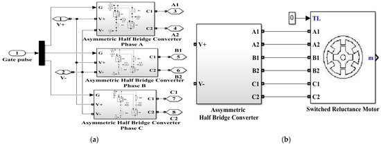
Figure 5.
Models: (a) three-phase AHBC; (b) SRM driven by the AHBC.
Basically, the heart of the motor drive is the power converter. Based on the selected type of power converter, the size, cost, and motor drive’s performance are of concern. As depicted in Figure 5b, the three-phase AHBC is fed to the SRM motor drive, thus avoiding the risk of short-circuits across the DC source. Table 2 shows the SRM motor’s specifications.
Table 2.
Data sheet of the SRM motor.
3. Control Strategy for the BDC with the AHBC-Based SRM Drive
A discussion of the control strategy for the PV and battery is provided in Section 3.1, and the control strategy for the SRM drive is discussed in Section 3.2.
3.1. Control Strategy for the PV and Battery
The control of the BDC for the battery’s energy storage and the PV model with MPPT is depicted in Figure 6. When the PV array receives adequate irradiation, it charges the battery through the BDC and delivers power to the load. Since battery and PV are used as sources, charging modes and multiple driving modes are obtained. To achieve a better performance, PI controllers are used for the battery control [8].
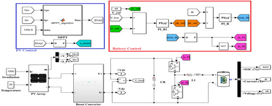
Figure 6.
Control of the PV integrated with the BDC model.
3.2. Control Strategy for the SRM Drive
In a solar-based EV, the battery is charged by PV and the GCU when under stand-still conditions. In a charging state by the PV, due to the PV panel’s low power, only one phase converter is used. When the level of power is larger than the PV, the battery is charged by the GCU. To achieve high power charging, the 3Φ converter works together in this situation. At a rotor position of the motor, the inductance of each phase variates due to the saliency structure. To overcome this issue, hysteresis control of the current is proposed, which is robust and stable under dynamic changes and used for the SRM control, as discussed in [9,10,11]. The simulation model shows the position of the control circuit for the SRM-powered controller model, as illustrated in Figure 7.
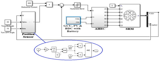
Figure 7.
Model for the SRM drive control.
4. Simulation Results of the Solar-Based SRM Drive Control
From Figure 7, five modes of operation for the solar-based SRM drive control are discussed, as well as the obtained results [12]. In mode 1, when the PV array fails to not produce energy, the GCU and battery operate as sources of power for the SRM drive. The obtained results for the output voltage of the solar-based SRM drive using the GCU and battery are depicted in Figure 8a, and the output characteristics of the SRM are represented in Figure 8b.
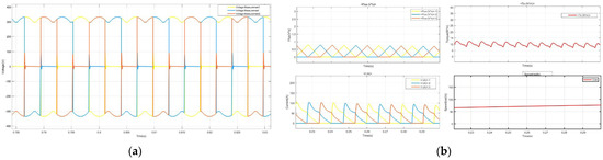
Figure 8.
Mode−1: (a) output voltage; (b) output characteristics of the SRM.
In mode 2, only the battery operates as a source when the PV is in intermittency and the grid fails. During this period, the stored energy in the battery energizes the SRM motor. As the battery energizes the load, the battery’s state of charge (SoC) is reduced to a minimum extent, with an initial SoC of 80% after which the battery should again be charged for further use, as shown in Figure 9a, which depicts the battery’s characteristics in this mode. Figure 9b presents the output characteristics of the SRM, and it is observed that the torque was less, and the speed constantly increased compared with the other modes.
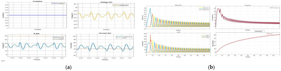
Figure 9.
Mode−2: (a) battery characteristics; (b) output characteristics of the SRM.
In mode 3, the motor runs on the PV. This is achieved by maintaining a constant irradiation of 1000 W/m2. This not only powers the motor but also charges the battery through the bidirectional converter circuit. When the isolation is high, during the summer times and at mid-noon, we use PV as a source to energize the battery. The sizing of the PV is conducted in such a way as to both energize the SRM and, at the same time, to charge the battery with an initial SoC of 10%. This charge, which is stored in the battery, is then used for running the motor when PV power is not usable. Figure 10a depicts the PV’s characteristics when the SRM drive is operated with only PV as a source. Figure 10b depicts the output characteristics of the SRM, and it is observed that the speed gradually increased, and the torque produced was higher when compared with mode 1.
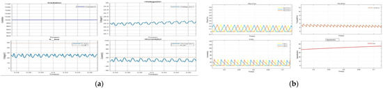
Figure 10.
Mode−3: (a) PV characteristics; (b) output characteristics of the SRM.
In mode 4, both the PV and battery are used to run the motor. The battery’s initial SoC is 45%, and the PV irradiance is kept constant at 1000 W/m2. Here, both the PV and battery are used in accordance to energize the SRM motor. This hybrid model is achieved by using the BDC, which includes a boost converter to boost the PV voltage and buck boost the battery. Figure 11a depicts the PV’s characteristics when the SRM drive is operated with both the PV and battery as sources. As discussed, the irradiation is kept constant at 1000 (W/m2), and the initial SoC is 45%. The battery’s characteristics in mode 4 are depicted in Figure 11b, and it is observed that the motor is run by the battery for the first part of the timeline and then the PV starts being used as a source for the motor and begins charging the battery as well. We understand that there is an increase in the state-of-charge characteristics. Figure 11c depicts the output characteristics of the SRM when the SRM drive is operated with both the PV and battery as sources, and it is observed that the torque produced is the highest when compared to the other two modes. Both the PV and battery sources powered the motor, and the speed increased gradually as well.
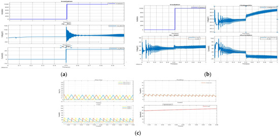
Figure 11.
Mode−4: (a) PV characteristics; (b) battery characteristics; (c) output characteristics of the SRM.
The proposed system achieves significant performance improvements over conventional systems. Simulation results demonstrate an enhanced torque output of 10 Nm and speed stability at 1500 rpm during hybrid operations, representing a 25% increase in torque and 7% improvement in speed compared with traditional battery-only systems. The self-charging mechanism achieves a charging efficiency of 90%, which is 15% higher than conventional methods, reducing the dependency on charging stations. The system also increases the battery’s state-of-charge (SoC) by 15% within one hour of operation, compared with 5–7% in traditional systems. With the observed values from the simulation’s results, the performance metrics for the proposed system and the conventional system are compared as listed in Table 3.
Table 3.
Comparison of the performance metrics for the proposed system and conventional system.
5. Hardware Implementation and Its Results
The hardware setup for the circuit is depicted in Figure 12. This is implemented with a lamp load to validate the basic functionality of the bidirectional converter and AHBC design in a controlled environment. This approach was chosen to ensure the safety and feasibility of the design before scaling up to an actual SRM drive application. A 240 V AC input is supplied to the step-down transformer, which steps down from 240 V to 15 V. A rectified filter converts AC-DC, which is then supplied as the input in the boost converter (BC). It boosts from 15 V to 97 V to light a 100 V lamp load. An approximately 240 V supply from the regulated AC supply source is given to the PIC microcontroller through a (12-0-12) V Transformer. The PIC microcontroller (16F877A), along with the driver circuit (20 kHz), rectifies the given AC supply to its equivalent DC. The output from the microcontroller is given to the designed boost converter, which boosts ccc15 V to ~100 V DC. The PIC controller provides gate pulses for the boost converter and the three-phase inverter. The PIC controls the drive circuit for both circuits, which provide gate signals to the converter circuit. The three-phase inverter converts DC to AC to light the lamp load.
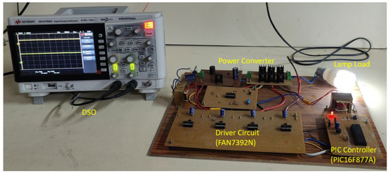
Figure 12.
Complete hardware setup for the proposed system.
Figure 13a depicts the gate pulse of the BC with a duty ratio of 0.5. Figure 13b depicts the input and output voltages of the BC. The observed values are an input voltage = 15 V and an output voltage (after boosting) = 97 V.
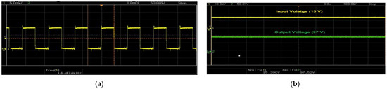
Figure 13.
Boost converter: (a) gate pulse; (b) waveform of the voltages.
Figure 14a depicts the inverter gate signal pulses for the switches. The input pulses are generated to excite the switches for conductance of the inverter. Figure 14b depicts the output voltages at the grid side for an average value of 96.5 V
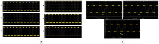
Figure 14.
Inverter: (a) gate signal pulses for the switches; (b) output voltage on the grid side.
6. Conclusions
The design of a bidirectional converter with an AHBC-based SRM drive using PV for EVs was implemented. The PV/GCU-battery-integrated circuit was used as a source for the asymmetrical half-bridge converter to power the SRM drive. This work helps in achieving the self-charging of the battery by using either the GCU or PV cells, as well as aids in the improvement in the performance characteristics. The proposed system achieves significant performance improvements over conventional systems. From the simulation results obtained, the output characteristics of the SRM, PV, and battery characteristics were observed and analyzed for the different modes. The simulation results demonstrate an enhanced torque output of 10 Nm and speed stability at 1500 rpm in the hybrid operation, representing a 25% increase in the torque and 7% improvement in the speed compared with traditional battery-only systems. The self-charging mechanism achieved a charging efficiency of 90%, which is 15% higher than conventional methods, reducing the dependency on charging stations. The system also increases the battery’s state-of-charge (SoC) by 15% within one hour of operation, compared with 5–7% in traditional systems. The implementation of the hardware prototype was conducted with a. lamp load instead of the SRM drive. In future work, the system will be adapted for real-world SRM drive applications, addressing any expected challenges and differences. By 2040, 55 percent of vehicles will be electric due to its cheap maintenance costs.
Author Contributions
Conceptualization, R.R.; methodology, S.H., S.M.A., M.V.S.K. and T.Y.N.K.; software, S.H., S.M.A., M.V.S.K. and T.Y.N.K.; validation, S.H., S.M.A., M.V.S.K. and T.Y.N.K.; visualization, S.H., S.M.A., M.V.S.K. and T.Y.N.K.; investigation, E.A.; resources, R.R.; writing—original draft preparation, E.A.; writing—review and editing, E.A.; supervision, R.R. All authors have read and agreed to the published version of the manuscript.
Funding
This research received no external funding.
Institutional Review Board Statement
Not applicable.
Informed Consent Statement
Not applicable.
Data Availability Statement
Data sharing is not applicable.
Acknowledgments
The authors would like to acknowledge the management of SSN college of engineering for the support.
Conflicts of Interest
The authors declare no conflicts of interest.
References
- Fan, D.; Zhu, X.; Quan, L.; Han, P.; Xiang, Z.; Wu, J. Driving Cycle Design Optimization of Less-Rare-Earth PM Motor Using Dimension Reduction Method. IEEE Trans. Energy Convers. 2023, 38, 1614–1625. [Google Scholar] [CrossRef]
- Peng, Y.; Chen, F.; Chen, F.; Wu, C.; Wang, Q.; He, Z.; Lu, S. Energy-Efficient Train Control: A Comparative Study Based on Permanent Magnet Synchronous Motor and Induction Motor. IEEE Trans. Veh. Technol. 2024, 73, 16148–16159. [Google Scholar] [CrossRef]
- Patel, D.D.; Fahimi, B.; Balsara, P.T. Electric Drives for Automotive Propulsion: A Comparative Study. In Proceedings of the 2024 IEEE Transportation Electrification Conference and Expo (ITEC), Chicago, IL, USA, 19–21 June 2024; pp. 1–7. [Google Scholar]
- Sayyad, J.K.; Nasikkar, P.S. Solar photovoltaic module performance characterisation using single diode modeling. E3S Web Conf. 2020, 170, 01023. [Google Scholar] [CrossRef]
- Pandiarajan, N.; Ramaprabha, R.; Muthu, R. Application of Circuit Model for Photovoltaic Energy Conversion System. Int. J. Photo Energy 2012, 2012, 410401. [Google Scholar] [CrossRef]
- Jadhav, S.; Devdas, N.; Nisar, S.; Bajpai, V. Design and Simulation of Bidirectional DC-DC Converter in Solar PV System for Battery Charging Application. In Proceedings of the 2023 IEEE International Conference on Power Electronics, Smart Grid, and Renewable Energy (PESGRE), Trivandrum, India, 17–20 December 2023; pp. 1–6. [Google Scholar]
- Liu, Y.; Wang, R. Fault diagnosis of power transistors in a power converter of SRM drive based on a state inverse solution. IET Electr. Power Appl. 2021, 15, 231–242. [Google Scholar] [CrossRef]
- Shukla, S.; Al-Durra, A.; El-Fouly, T.H.M.; El-Saadany, E.F. Bidirectional Power Flow Control of Solar PV Array Based Multifunctional E-Mobility Charger. In Proceedings of the 2nd International Conference on Smart Power & Internet Energy Systems (SPIES), Bangkok, Thailand, 15–18 September 2020; pp. 391–396. [Google Scholar]
- Pires, V.F.; Pires, A.J.; Cordeiro, A.; Daniel, F. A Review of the Power Converter Interfaces for Switched Reluctance Machines. Energies 2020, 13, 3490. [Google Scholar] [CrossRef]
- Shah, V.; Payami, S. Fully Integrated Multilevel Power Converter for SRM Drive With Charging Capabilities (G2V) for Electric Vehicle Application. IEEE J. Emerg. Sel. Top. Ind. Electron. 2023, 4, 198–208. [Google Scholar] [CrossRef]
- Shambhavi, K.N.; Chayapathy, V. Power Converter Configurations for Switched Reluctance Motors: A Review. Int. Res. J. Eng. Technol. (IRJET) 2022, 9, 2045–2048. [Google Scholar]
- Available online: www.mathworks.com (accessed on 6 October 2023).
Disclaimer/Publisher’s Note: The statements, opinions and data contained in all publications are solely those of the individual author(s) and contributor(s) and not of MDPI and/or the editor(s). MDPI and/or the editor(s) disclaim responsibility for any injury to people or property resulting from any ideas, methods, instructions or products referred to in the content. |
© 2025 by the authors. Licensee MDPI, Basel, Switzerland. This article is an open access article distributed under the terms and conditions of the Creative Commons Attribution (CC BY) license (https://creativecommons.org/licenses/by/4.0/).