Proceeding Paper

Real-Time Detection and Counting of Melted Spatter Particles During Deposition of Biomedical-Grade Co-Cr-Mo-4Ti Powder Using the Micro-Plasma Transferred Arc Additive Manufacturing Process †

1
School of Computing, Engineering, and Intelligent Systems, Ulster University, Derry~Londonderry Campus, Northland Road, Derry/Londonderry BT48 7JL, Northern Ireland, UK
2
Department of Mechanical Engineering, Indian Institute of Technology Indore, Simrol 453552, MP, India
*
Author to whom correspondence should be addressed.
Presented at the 2024 IEEE 6th Eurasia Conference on IoT, Communication and Engineering, Yunlin, Taiwan, 15–17 November 2024.
Eng. Proc. 2025, 92(1), 78; https://doi.org/10.3390/engproc2025092078
Published: 21 May 2025
(This article belongs to the Proceedings of 2024 IEEE 6th Eurasia Conference on IoT, Communication and Engineering)

Abstract

Spatters in the powder-based metal additive manufacturing processes influence deposition quality, part surface quality, and internal defects. We developed a novel video analysis method to monitor and count the melted spatter particles of biomedical-grade Co-Cr-Mo-4Ti powder particles in depositing layers using a micro-plasma transferred arc additive manufacturing (M-PTAAM) process. We captured the spatters using a weld-monitoring camera and building datasets of videos and monitored different combinations of M-PTAAM process parameters. We captured videos of the melted spatter particles and counted the melted spatter particles in real time using a Kalman filter. The weld-monitoring camera captured the melted spatter particles and the fumes generated by the evaporated spatter particles. The video processing algorithm was developed in this study to accurately capture melted spatter particles. In images without fumes, nearly all melted spatter particles were successfully detected. Even in images with the presence of fumes, the algorithm maintained a detection accuracy of 90%. The real-time melted spatter count particle exhibited a powder feed rate changing from 30 to 35 g/min and then to 50 g/min. The melted spatter particle count was lowest at a powder feed rate of 30 g/min and increased with the increasing powder feed rate.

1. Introduction

Spatters consist of melted or unmelted powder particles that do not integrate into the deposited layers. Unmelted spatter particles are reused after proper characterization and sieving but melted spatter particles are wastes, leading to the loss of costly powder. Additionally, the fumes from evaporated spatter particles pose health hazards. Therefore, reducing the number of melted spatters is essential from both economical and safety aspects.
Various powder-based additive manufacturing (AM) processes such as powder bed fusion (PBF) and directed energy deposition (DED) have been used in response to the challenge posed by spatter particles. Spatter particles affect product quality, leading to material loss. Spatters are in the form of melted or unmelted powder particles. The unmelted spatter particles are post-processed and reused for another printing process. However, melted spatter deposits elsewhere on the build surface cause irregular surface morphology and re-enter the melt pool with defects [1] such as porosity or inclusions. This contaminates the surrounding unmelted powder particles, reducing the recyclability and purity of unused powder. The melted spatter particles evaporate, causing hazardous gas fume generation, leading to safety issues for the operator.
Previous studies reported that the melted spatter particles cause keyhole porosity [2,3]. Wang et al. [4] reported that the melted spatter particles are usually of two types: one is the metal droplet ejected from the melt pool and another is the melted powder particles bounced back from the melt pool due to recoil pressure. Zheng et al. [5] found that spatter particles generate an undesired effect and result in the contaminated re-coating and melting of powder, causing internal defects in the laser-powder bed fusion (PBF) process. In the selective laser melting (SLM) process, the effect of the oxidation behavior of the melted spatter particles is observed [6]. It is found that the melted spatter particles that turn into gas fumes are hazardous with a high environmental impact.
In situ real-time monitoring of the AM process is used to understand the spatter particle distribution to control and minimize the influence of spatter particles. Particularly for the DED processes, Iquebal et al. [7] proposed a high-speed camera-based imaging methodology to capture the spatter particles in real time. They used a Kalman filter to track and count the moving spatter particles. Using high-speed camera imaging, Ermurat et al. [8] captured a powder flow rate at 20 frames per second, making it suitable to identify the trajectory of the spatter particles. For a similar AM process, Nassar et al. [9] used a spectroscopy-based imaging technique to capture the plumes during the deposition process. Hofmeister et al. [10] used a charge-coupled device (CCD) camera to capture a powder flow rate and analyze the melt pool dynamics and its influence on the spatter particles.
Imaging powder particles and video analysis are used to track the spatter particles. In this study, we developed a high dynamic range (HDR) camera-based deposition monitoring system for the M-PTAAM process to capture melted spatter particles in real time. We created the video dataset of depositions and spatter particles for various combinations of M-PTAAM process parameters. Each video frame was processed to capture the melted spatter particles. Using a Kalman filter, we detected the moving spatter particles and counted the particles in real time.

2. Material and Methods

Figure 1 depicts the methodology used to track and count the melted spatter particles in real time. Experiments were conducted on M-PTAAM with the HDR camera and the recorded video to capture the real-time movement of melted spatter particles.

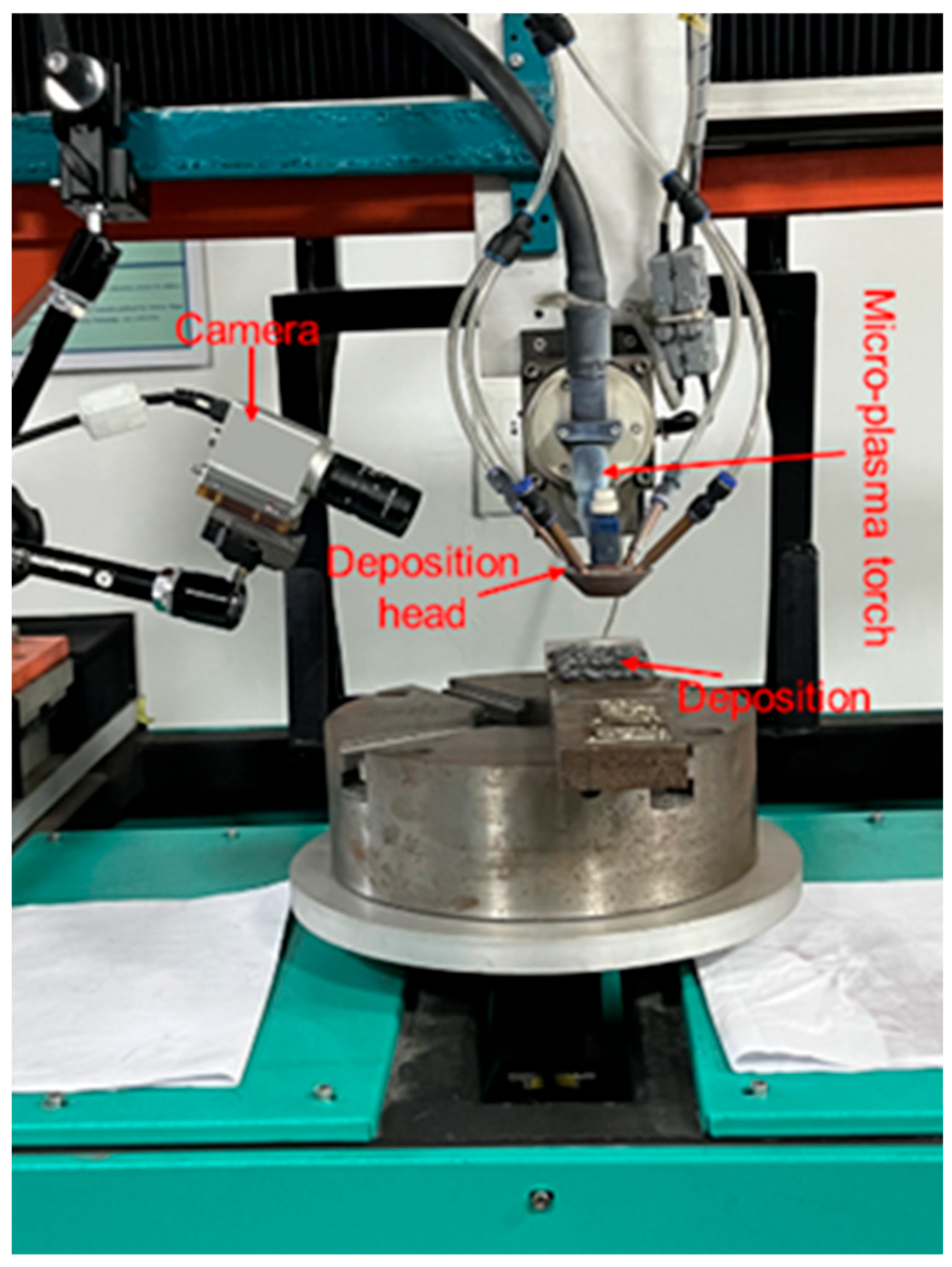
2.1. Data Collection

Figure 2 depicts the M-PTAAM setup with a camera for monitoring the biomedical-grade Co-Cr-Mo-4Ti powder material deposition process. The process was monitored using a Xiris XVC-1000 HDR (Xiris Automation GmbH, Ratingen, Germany) monochrome camera, and the depositions and the spatter particles were captured. Initially, the dataset was built for depositing layers using various combinations of the M-PTAAM parameters, as shown in Table 1. The process parameters were selected on the basis of identifying the influence of the changing powder feed rate on the number of melted spatter particles.

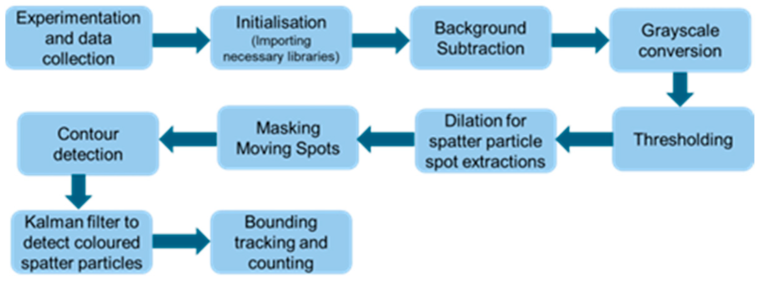
2.2. Image Processing and Spatter Contour Extraction

The first step in image processing was to initialize the essential libraries, such as OpenCV, NumPy, and Pandas, imported to manage video processing, numerical operations, regular expressions, file handling, and data management. Then, background subtraction was performed, where the static background was subtracted from the moving spatter particles captured in the foreground. The background over time and deviations were identified from moving objects. For background learning, the number of frames for learning was set to 500, and the threshold for movement detection was 50. The moving particle areas were identified in the white regions while making the static background black (Figure 3).
Each frame was represented in grayscale, and a binary threshold was applied. Any pixel value above 150 was assigned to white and any pixel below 150 was assigned to black. This operation was used to isolate bright areas and track the moving spatter particles in the darker background. In the frames, different-sized spatter particles were observed. To enhance the detection process of small spatter particles, a dilation operation was carried out. Initially, a small 2 × 2 kernel was used to dilate small spatter by slightly increasing their size. Thereafter, a larger 5 × 5 kernel was used to dilate these spots, making them prominent in the mask. Then, the moving mask was generated by performing a bitwise AND operation between the dilated image and the foreground mask obtained from background subtraction. This operation kept the white areas of moving spatter particle in the dilated image. Then, contours were detected, where boundaries of the detected white spots in the moving mask were retrieved to reduce the complexity. The information on contour detection was used for the Kalman filter to detect and count melted spatter particles.

2.3. Kalman Filter for Spatter Detection and Counting

The Kalman filter is widely used to track moving objects in images and videos [11]. There are two main challenges involved in tracking the moving spatter particles. In distinguishing spatter particles from noise or moving objects, the gas fumes of the evaporated particles are moving and have similar color to spatter particles while in continuous monitoring of particles. Particles appear in front of the tracked particle, which may terminate the tracking due to different velocities. Therefore, a Kalman filter is used to address such challenges [12].
In this study, the Kalman filter was used to predict the position of spatter particles and generate a bounding box around the contour of spatter particles. The current state (xk) of the moving spatter particle is predicted based on the previous position (xk−1) and using Equation (1):
x k = A · x k 1 + B · u
where u is the velocity of a particle, and A and B are the state transition and control input matrices, respectively.
The state of the moving particle was updated in each frame by using the Kalman gain (Kk) and the measurement residual (yk). The updated position is calculated as
x k = x k + K k · y k
The Kalman gain (Kk) is calculated as
K k = P k · H T · H · P k · H T + R   1    
where Pk is the error convergence prediction, HT is the measurement matrix mapped with the state vector, and R is the measurement residual (yk).
yk is the difference between the actual and predicted location of the spatter particles:
y k = z k H · x k
where zk is the actual measurement of the position.
The bounding box around the moving spatter particles was generated based on the state vector predicted using Equations (1) and (2). The state vector is represented as
x = P o s i t i o n x P o s i t i o n y V e l o c i t y x V e l o c i t y y          
Once the position of the moving spatter particle was predicted, a bounding box was created around the contour of the moving spatter particle represented with green color. The bounding box was centered on the estimated position of the spatter particle and measured as follows:
The top-left corner of the bounding box was calculated as
P o s i t i o n x w 2 , P o s i t i o n y h 2  
Bottom-right corner was calculated as
P o s i t i o n x + w 2 , P o s i t i o n y + h 2  
where w and h are the dynamically derived width and height of the bounding box.
Then, in the green bounding boxes, the melted spatter particles were counted in each frame. The greyscale image was converted to a hue saturation value (HSV) color space to make color-based filtering easier. A range of HSV values was defined by identifying pixels that fall within the green range.
In this study, the lower boundary of (H, S, V) was set to (30, 40, 40) while the upper boundary was set to (90, 255, 255). This range was adjusted to be broad enough to capture different shades of green. Using these bounds, a binary mask was created to detect and isolate green-colored regions within the bounding box. Then, the counter was set to count the total green-colored bounding boxes in each frame, showing the count of melted spatter particles.

3. Results and Discussions

3.1. Kalman Filter-Based Monitoring of Melted Spatter Particles

Figure 4 depicts the comparison of the actual melted spatter and the measured melted spatter for different experimental conditions. The figure on the left shows the melted spatter particles, while the processed frame in which the spatter particles are counted using the Kalman filter is shown. In the raw image, the spatter particles were manually counted, and the count was compared against the automatic measurement. The detection algorithm performed well in capturing and counting the spattered particles (Figure 4a). Figure 4b shows the gas fumes from evaporated spatter particles with moving spatter particles. The algorithm counted spatter particles in the gas fume and predicted the false positives (FPs) of the melted spatter particle. Unclear regions interfered with spatter visibility, causing the system to miss several spatter particles (Figure 4c). This led to the false negatives (FNs) in predicting melted spatted particles. Fumes and unclear regions produced discrepancies between the actual and measured spatter particles. However, the algorithm detected melted spatter particles with 90% accuracy.

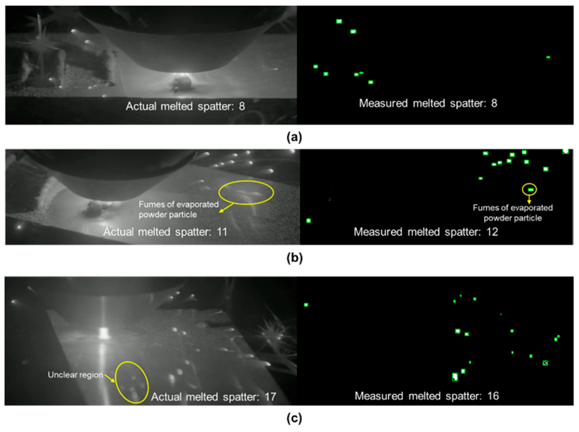
3.2. Real-Time Counting of Melted Spatter Particles

Figure 5 shows the real-time spatter particle count for varying current and powder feed rate settings. Figure 5a shows the real-time count of spatter particles for a low powder feed rate (30 g/min). The spatter particle count fluctuated between 2 and 20 over time due to changes in process conditions, such as fluctuations in powder delivery or energy input. At a slightly higher powder feed rate (35 g/min), the particle count fluctuated between 4 and 25. Around 47 s, the spatter count decreased to 0 due to a stop in powder feeding or delivery. The higher the powder feed rate (50 g/min), the highest the levels of the spatter particle count, with values fluctuating between 30 and 100 and even reaching up to 138.

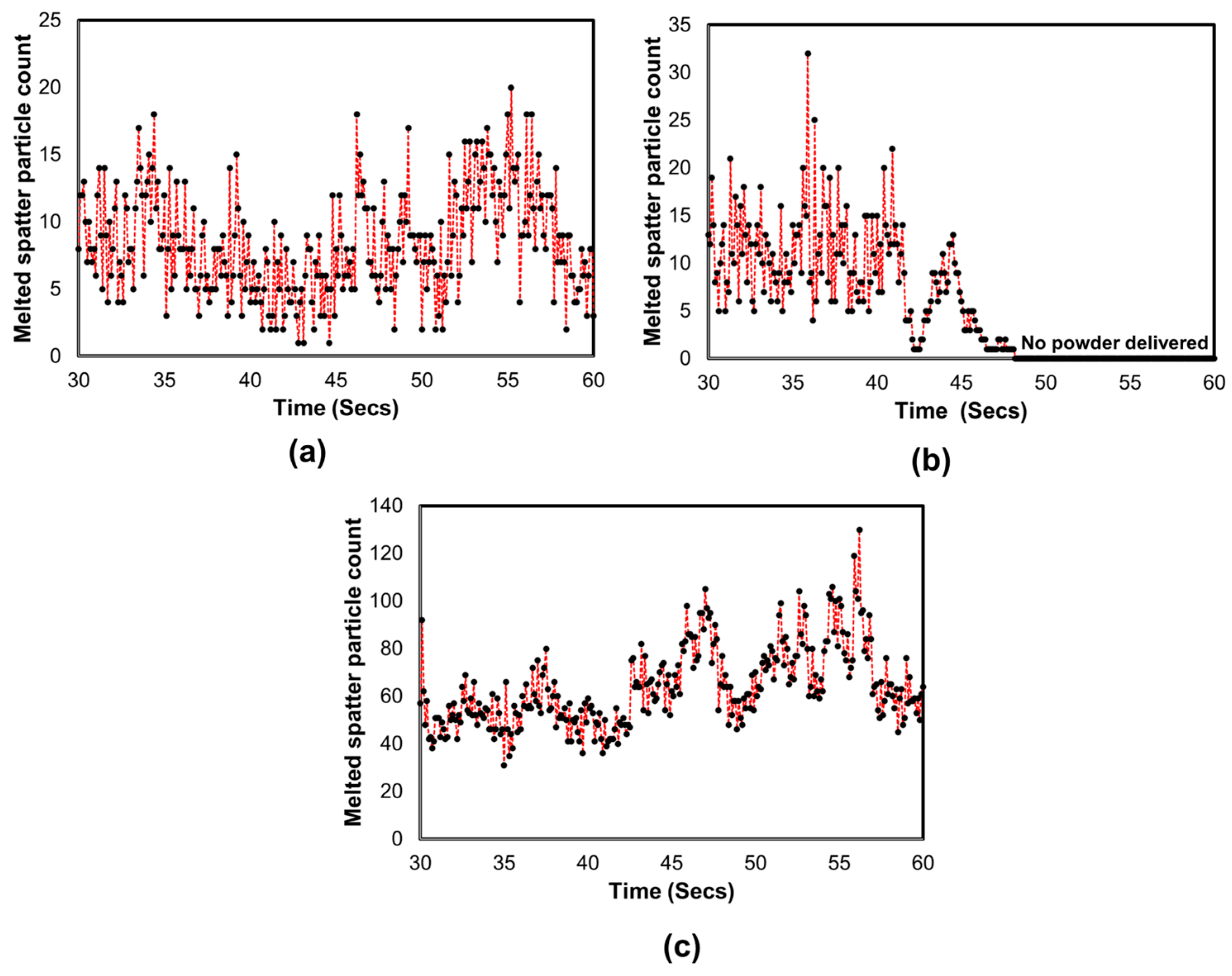
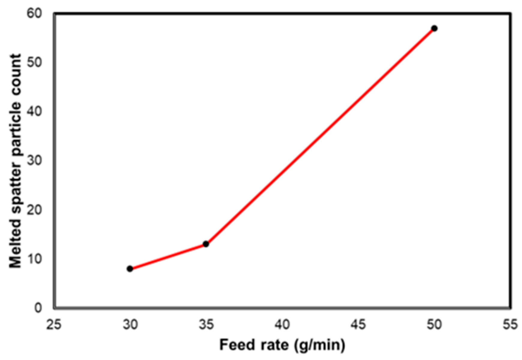
3.3. Influence of Powder Feed Rate on Melted Spatter Particles

Figure 6 depicts the influence and relationship between the powder feed rate and the number of melted spatter particles produced during the deposition process. The increasing powder feed rate from 35 to 50 g/min increased the number of spatters. This indicates that higher feed rates made the process spatter-prone due to the excess material interacting with the heat source, leading to more molten material being ejected.

4. Conclusions

We monitored and counted melted spatter particles in real time using M-PTAAM, image processing, and a Kalman filter. An HDR camera was integrated into M-PTAAM, and the depositions were recorded for depositing biomedical-grade Co-Cr-Mo-4Ti material. The developed monitoring system captured the depositions, melted spatter particles, and gas fumes from evaporated particles with clarity. The Kalman filter was capable of automatically counting the melted spatter particles with 90% accuracy. The automated particle detection algorithm under- or over-estimated spatter counts in complex scenarios with fumes or unclear regions. The results of this study showed that spatter formation can be controlled and monitored in real time for process optimization.

Author Contributions

Conceptualization, S.N., D.N. and Y.P.; methodology, S.N., D.N. and Y.P.; software, S.N., D.N. and Y.P.; validation, S.N. and D.N.; formal analysis, S.N. and D.N.; investigation, S.N., D.N. and Y.P.; resources, S.N., D.N. and N.K.J.; data curation, S.N., S.C., D.K., D.N., N.K.J. and Y.P.; writing—original draft preparation, S.N., D.N. and Y.P.; writing—review and editing, S.N., S.C., D.K., D.N., N.K.J. and Y.P.; visualization, S.N., D.N. and Y.P.; supervision, S.C., D.K. and N.K.J.; project administration, D.N.; funding acquisition, D.N., S.N., S.C. and D.K. All authors have read and agreed to the published version of the manuscript.

Funding

This research was supported by the Department for Science, Innovation, and Technology (DSIT), which provided International Science Partnership Funding (ISPF) to Ulster University via the Department for the Economy (DfE) Northern Ireland.

Institutional Review Board Statement

Not applicable.

Informed Consent Statement

Not applicable.

Data Availability Statement

Data available on request.

Conflicts of Interest

The authors declare no conflicts of interest.

References

  1. Patil, D.B.; Nigam, A.; Mohapatra, S.; Nikam, S. A deep learning approach to classify and detect defects in the components manufactured by laser directed energy deposition process. Machines 2023, 11, 854. [Google Scholar] [CrossRef]
  2. Wolff, S.; Wu, H.; Parab, N.; Zhao, C.; Ehmann, K.; Sun, T.; Cao, J. In-situ high-speed X-ray imaging of piezo-driven directed energy deposition additive manufacturing. Sci. Rep. 2019, 9, 962. [Google Scholar] [CrossRef] [PubMed]
  3. Thompson, S.M.; Bian, L.; Shamsaei, N.; Yadollahi, A. An overview of Direct Laser Deposition for additive manufacturing; Part I: Transport phenomena, modeling and diagnostics. Addit. Manuf. 2015, 8, 36–62. [Google Scholar] [CrossRef]
  4. Wang, D.; Ye, G.; Dou, W.; Zhang, M.; Yang, Y.; Mai, S.; Liu, Y. Influence of spatter particles contamination on densification behavior and tensile properties of CoCrW manufactured by selective laser melting. Opt. Laser Technol. 2020, 121, 105678. [Google Scholar] [CrossRef]
  5. Li, Z.; Li, H.; Yin, J.; Li, Y.; Nie, Z.; Li, X.; You, D.; Guan, K.; Duan, W.; Cao, L.; et al. A Review of Spatter in Laser Powder Bed Fusion Additive Manufacturing: In Situ Detection, Generation, Effects, and Countermeasures. Micromachines 2022, 13, 1366. [Google Scholar] [CrossRef] [PubMed]
  6. Simonelli, M.; Tuck, C.; Aboulkhair, N.T.; Maskery, I.; Ashcroft, I.; Wildman, R.D.; Hague, R. A Study on the Laser Spatter and the Oxidation Reactions During Selective Laser Melting of 316L Stainless Steel, Al-Si10-Mg, and Ti-6Al-4V. Metall. Mater. Trans. A 2015, 46, 3842–3851. [Google Scholar] [CrossRef]
  7. Iquebal, A.S.; Yadav, A.; Botcha, B.; Gorthi, R.K.; Bukkapatnam, S. Tracking and quantifying spatter characteristics in a laser directed energy deposition process using Kalman filter. Manuf. Lett. 2022, 33, 692–700. [Google Scholar] [CrossRef]
  8. Ermurat, M.; Arslan, M.A.; Erzincanli, F.; Uzman, I. Process parameters investigation of a laser-generated single clad for minimum size using design of experiments. Rapid Prototyp. J. 2013, 19, 452–462. [Google Scholar] [CrossRef]
  9. Nassar, A.R.; Starr, B.; Reutzel, E.W. Process monitoring of directed-energy deposition of Inconel-718 via plume imaging. In Proceedings of the 26th Annual International Solid Freeform Fabrication Symposium—An Additive Manufacturing Conference (SFF 2015), Austin, TX, USA, 10–12 August 2015. [Google Scholar]
  10. Hofmeister, W.; Knorovsky, G.A.; Maccallum, D.O. Video monitoring and control of the LENS process. In Proceedings of the American Welding Society 9th International Conference of Computer Technology in Welding, Detroit, MI, USA, 30 November 1999. [Google Scholar]
  11. Kalman, R.E. A New Approach to Linear Filtering and Prediction Problems. ASME. J. Basic Eng. 1960, 82, 35–45. [Google Scholar] [CrossRef]
  12. Billoir, P.; De Cian, M.; Günther, P.A.; Stemmle, S. A parametrized Kalman filter for fast track fitting at LHCb. Comput. Phys. Commun. 2021, 265, 108026. [Google Scholar] [CrossRef]
Figure 1. Methodology for tracking and counting melted spatter particles.
Engproc 92 00078 g001
Figure 2. Camera integrated with M-PTAAM process for process monitoring.
Engproc 92 00078 g002
Figure 3. Processing of (a) raw video frames for (b) detecting contours of moving melted spatter particles.
Engproc 92 00078 g003
Figure 4. Comparison of actual and measured melted spatter particle count: (a) Current: 17; powder feed rate: 30. (b) Current: 17; powder feed rate: 35. (c) Current: 12; powder feed rate: 50.
Engproc 92 00078 g004
Figure 5. Spatter particles count in real time: (a) Current: 17; powder feed rate: 30. (b) Current: 17; powder feed rate: 35. (c) Current: 12; powder feed rate: 50.
Engproc 92 00078 g005
Figure 6. Effect of varying powder feed rate on melted spatter particles.
Engproc 92 00078 g006
Table 1. Combination of M-PTAAM process parameters.
Exp. no.Current (A)Powder Feed Rate (g/min)Deposition Head Travel Speed (mm/min)
1173055
21735
31250
Disclaimer/Publisher’s Note: The statements, opinions and data contained in all publications are solely those of the individual author(s) and contributor(s) and not of MDPI and/or the editor(s). MDPI and/or the editor(s) disclaim responsibility for any injury to people or property resulting from any ideas, methods, instructions or products referred to in the content.

