1. Introduction
Frequencies susceptible to interferences in the surrounding environment are internal or external. In addition, internal noises disrupt the operation of the device and cause the quality of the signal to fluctuate. Switching components such as inductors, transformers, transistors, and parts of the circuit [
1] contribute to the instantaneous changes in electricity. External noises affect the signals by coupling poor electromagnetic interference (EMI) shielding. External noises are produced by strong electromagnetic radiation with almost or the same frequency that cancels the existing communication signal, which is referred to as destructive interference [
2]. The external source of the interference must be higher than that of antenna gain and signal power to achieve destructive interference in wireless communications. Since modern devices are sensitive to detecting frequencies [
3], especially near the operating frequencies, devices experience such effects and interferences.
Multiple frequencies must be radiated simultaneously in a single antenna for efficient wireless communications. Therefore, designing an antenna capable of operating in a large bandwidth is crucial in broadcast transmissions received by radios, cellphones, satellites, and televisions tuned in at the same band of frequencies [
4,
5,
6]. Antennas have different architectures depending on the polarization of the radiation. In a patch antenna, the pattern of polarization is critical to effectively resonate to the same designed receiving antennas for better signal quality. The patch antenna polarization is linear or circular based on the microstrip design. The advantage of patch antennas is that they are easy to fabricate, cheap, and have high dielectric breakdown [
7,
8], since most patch antennas use FR-4 that operates at lower and higher microwave frequencies.
In this study, a phased array patch antenna was designed in Ansys, and the final measurements were used to design the same dimensions in AutoCAD for printing it on the double-layered photosensitive FR-4 copper board. Ansys was used especially in simulating the frequencies for IEMI to the input of the antenna and the initial design of a patch antenna operating at 35–4.4 GHz at 50-ohm impedance. Radiation pattern, directivity, and total gain under these parameters were also obtained.
We designed and fabricated an antenna that operates at interfering frequencies of 35-960MHz. We also designed a 50 ohm 2 × 2 inset-fed phased array patch microstrip patch antenna with a ground plane in Ansys for simulation and analysis. The design was printed for the fabrication of the 2 × 2 antennas on a double-layered photosensitive FR-4 copper board using only light, developer solution, and copper etching. We tested the antenna’s interference by connecting the input of the antenna to the output of the signal generator ADF4351 and radiating the interfering signal to a radio.
This fabricated antenna is beneficial in EMI shielding and communication testing, as it tunes the same polarization and frequency of the devices to monitor the sensitivity of the receiving antenna and operating frequency. Such improvement to the EMI shielding of electronic components and antenna design enables avoiding interference.
2. Design and Analysis
The design in this study included ADF 4351 generating signals of 35–960 MHz to the input of the antenna. To improve the signal quality and power from the signal generator, it is required to have a power amplifier to have a strong signal radiated by patch antennas. Along with the 20 dB power amplifier, it must pass through the bandpass filter so only frequencies within the range are radiated by the antennas, minimizing probabilities of internal noises in the circuit. These are part of the processes to increase signal integrity. Lastly, ADF 4351 generates multiple frequencies at different ranges that are radiated using a wireless spectrum analyzer and receive the range of frequencies 35–960 MHz, which are strong and capable of EMI.
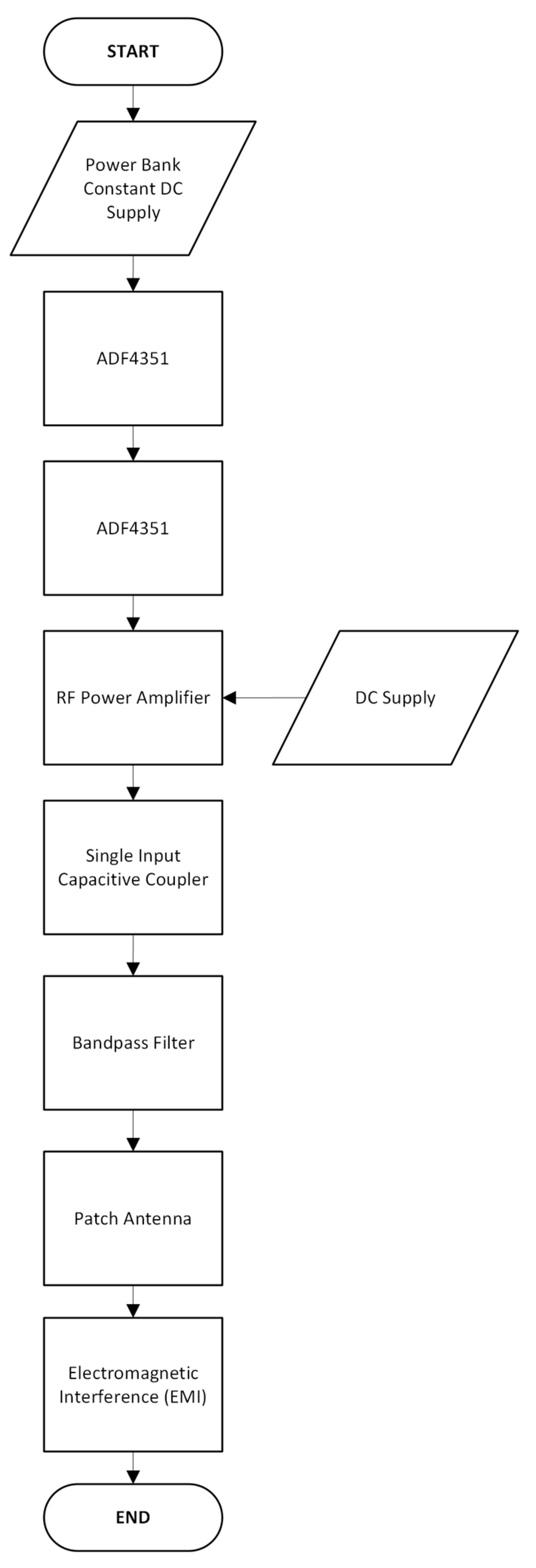
2.1. System Process
Figure 1 shows the operation of the connected circuits and devices from the signal generator to the patch antenna as the signal’s destination. It begins with powering the signal generator to produce the frequencies required for interference. The process uses the incoming signal to be amplified by a 20 dB power amplifier linked to the next circuit. The bandpass filter was a ceramic capacitor in series. The interfering signal is radiated directly from the output of the filter to the input of the patch antennas. The DC-biased circuits are used in the amplifier, and the ADF 4351 with DC batteries is used to turn the circuit on. The framework and the flowchart do not differ from each other since their straightforward operation is the same process and is simple without complexity.
2.2. Antenna Ansys Design
The antenna’s dimensions were designed in Ansys before using the measurements in AutoCAD later. There are boundaries for the E-field for simulating the constraints of the physical object and space in the simulation concerning the frequencies excited at the feed point. It is the boundary where the radiation will propagate. Three boundaries were determined in this study. The first boundary, E1, is the ground plane behind the patch antenna where the signal is reflected towards the front of the antenna. Second, the patch antenna, E2, is the main boundary where the signal comes from the wave port to the inset feed of the antennas. The third boundary, Rad1, is the medium that the electromagnetic waves in the simulator use as the space to propagate.
2.3. Antenna AutoCAD Design and Fabrication
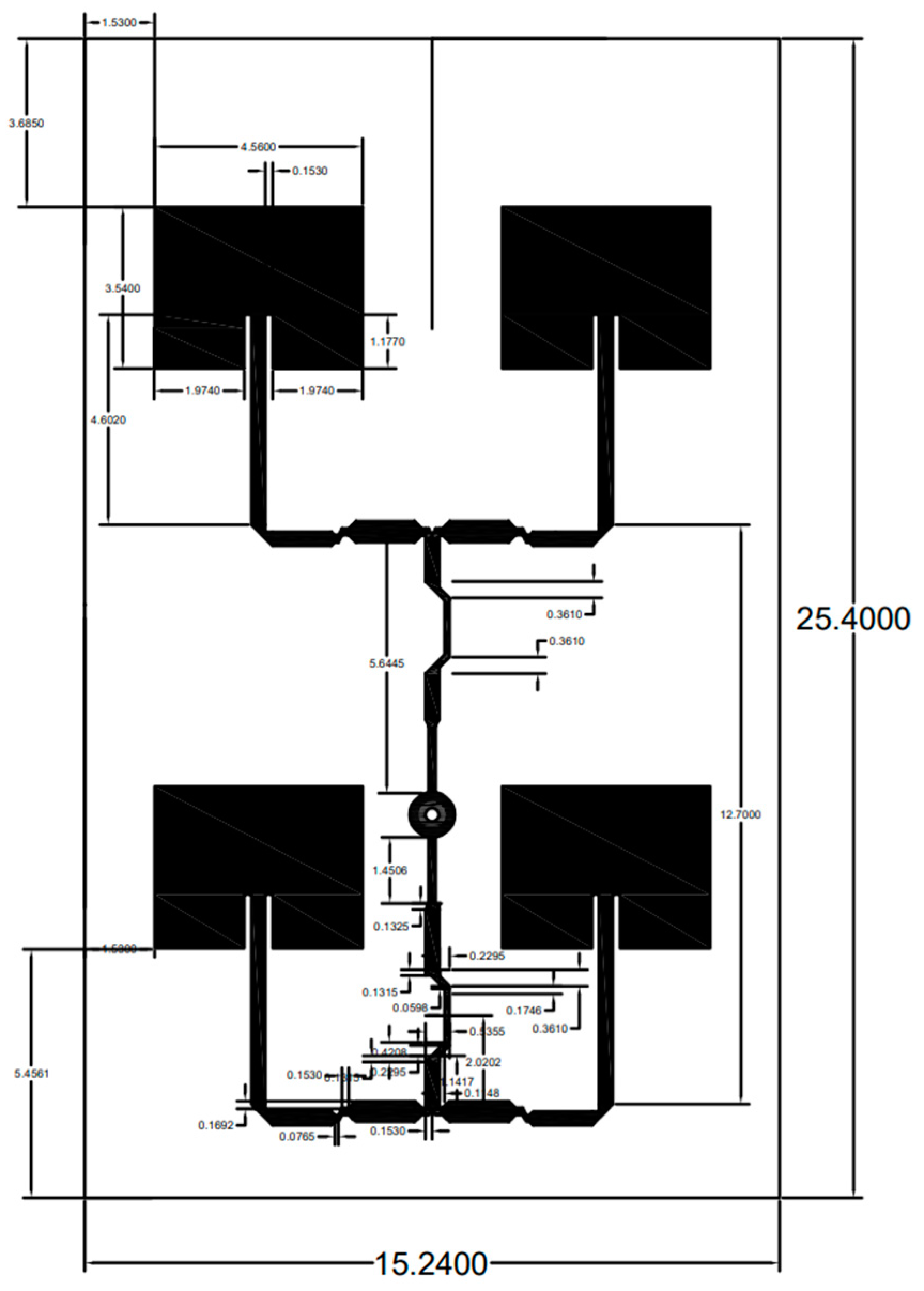
Dimensions, cuts, and traces were determined before connecting to the inset feed of the antennas. The slanted cuts on the trace were avoided due to the signal reflections and radiation to the edges. The small traces were designed to avoid radiation on the edges and pushing the signal due to restriction to larger areas of the traces to the main antennas. The large traces were used to draw more power and signals from the feed point. The outer dimensions of the copper board were 15.24 cm (about 6 in) and 25.4 cm (about 10 in) (
Figure 2).
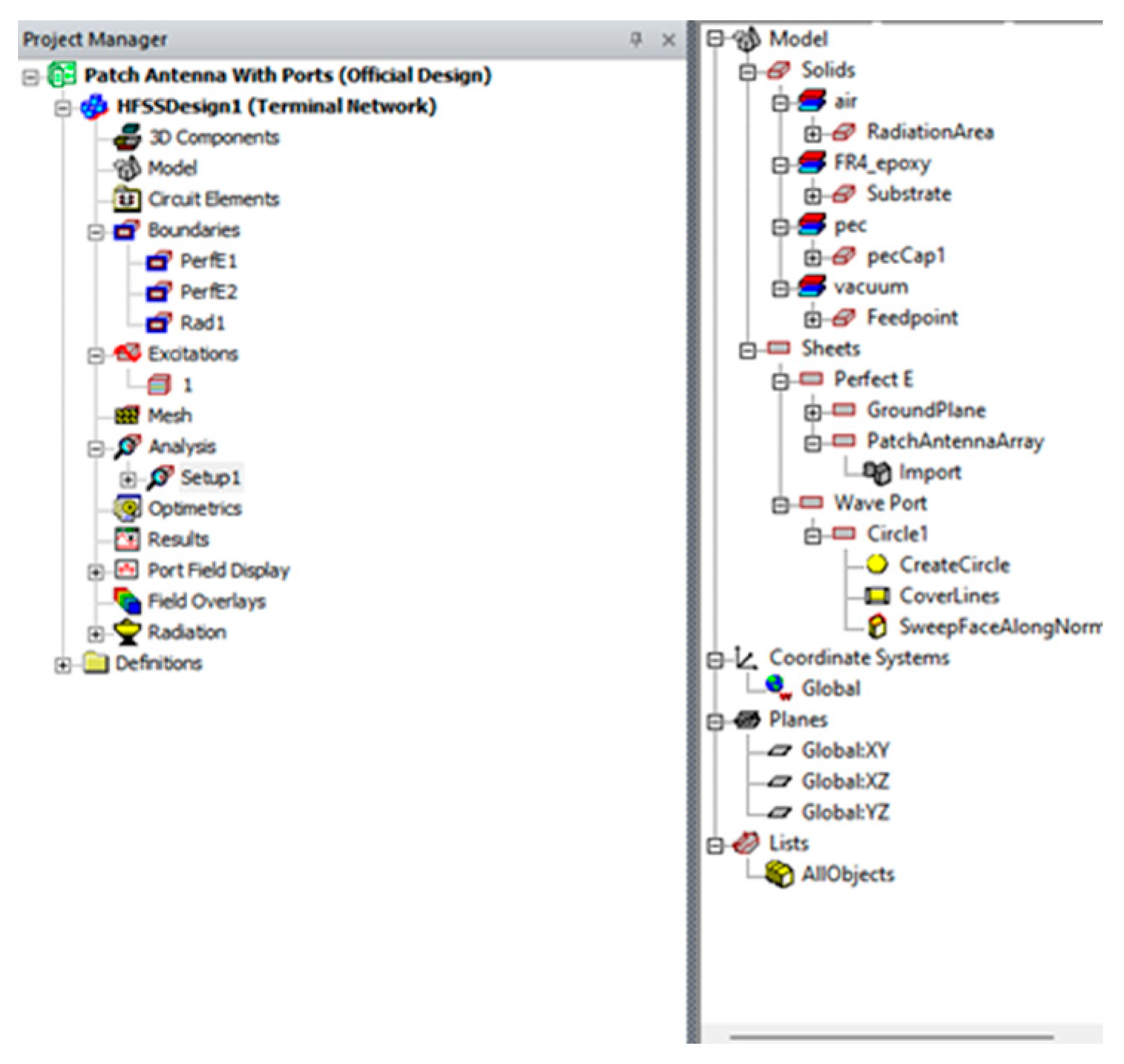
A microstrip patch antenna was modeled and simulated to evaluate its electromagnetic performance. The structure comprises a conducting path on an FR4 substrate with a ground plane, and is excited through a feed point port. Appropriate boundary conditions were applied to replicate an open-space radiation. The simulation focused on analyzing return loss and radiation characteristics. The model configuration and simulation setup are illustrated in (
Figure 3).
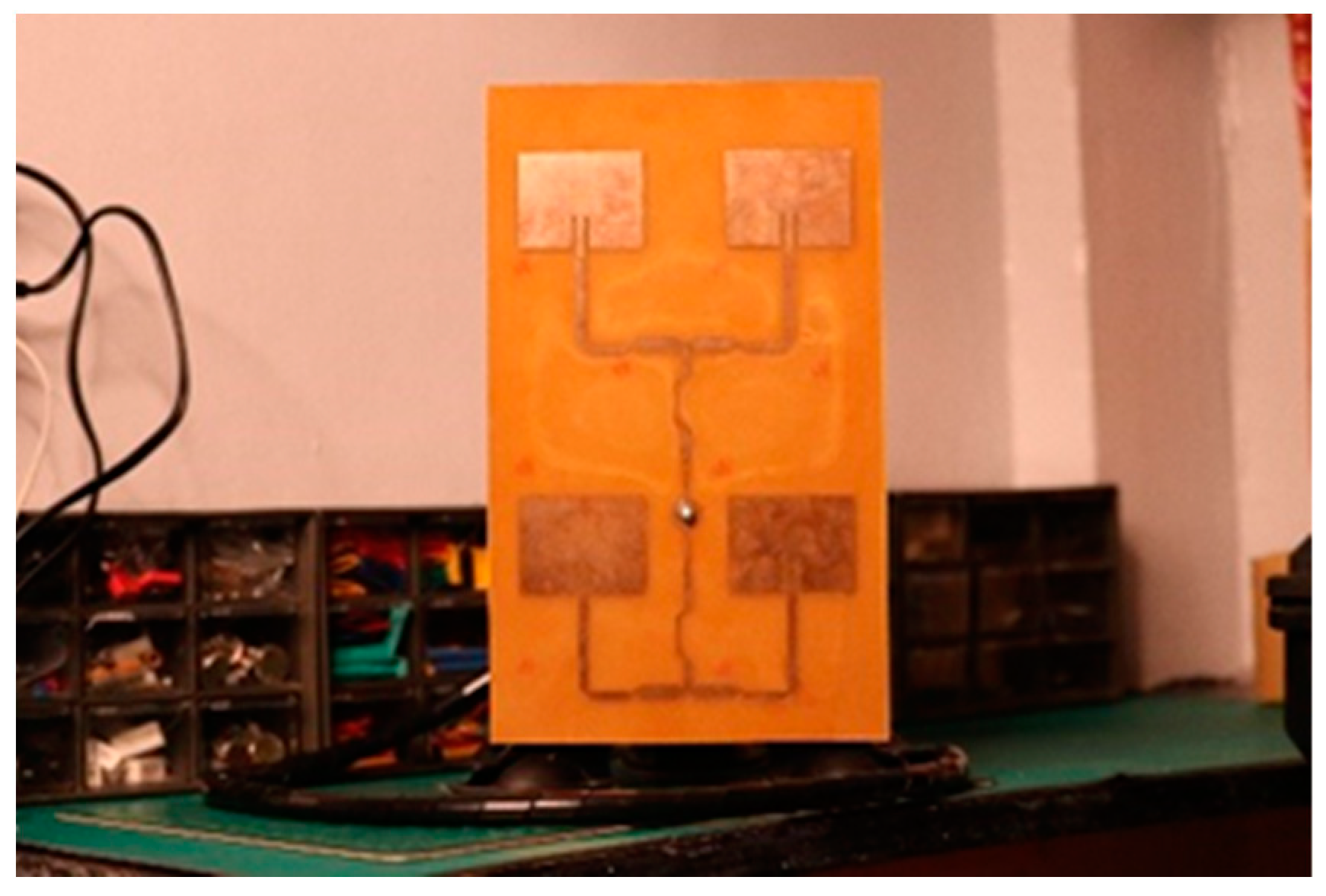
The 2D model from AutoCAD was printed with the same size as the dimensions of the copper board. However, there were manufacturing errors in the PCB board when actual measurements were performed using a caliper. To create parchment that adhered only to the face of the board, the paper was soaked in oil. Then, it was exposed to high-intensity light for 30 min. Afterward, it was washed using a developer solution and etched. The green paint on the antenna and ground plane was removed by using pure acetone. Fabricated on a double-layered photosensitive FR-4 copper board, the male N-type connector probe was soldered on the copper tracing in the front view 2 × 2 patch antennas. The antenna was attached to a modified camera mount, and an RG-142 coaxial cable was used. It radiated frequencies effectively, as observed on the wireless spectrum analyzer, wherein the waveforms were detected with a high amount of power from the range of 35–960 MHz (
Figure 4).
3. Results and Discussions
3.1. Antenna Ansys Setup
A sample frequency of 35 MHz was used as the test frequency to determine the polarization of the antenna at different phases observed in the 3D polar plot. A driven solution setup tab was used to set the mode for the test’s frequencies for the antenna in multiple ranges from Hz to THz. Under the adaptive solution settings in solution frequency, three modes were chosen: single, multi-frequencies, and broadband. The single-frequency setup was used to easily visualize the behavior of the frequency due to the polarization of the antenna. Only one adaptive pass was used to lessen the runtime analysis, and a low delta S was used to increase the accuracy of the radiation pattern, lobe, and angle of direction beginning from the wave port.
3.2. Polarization of the Antenna
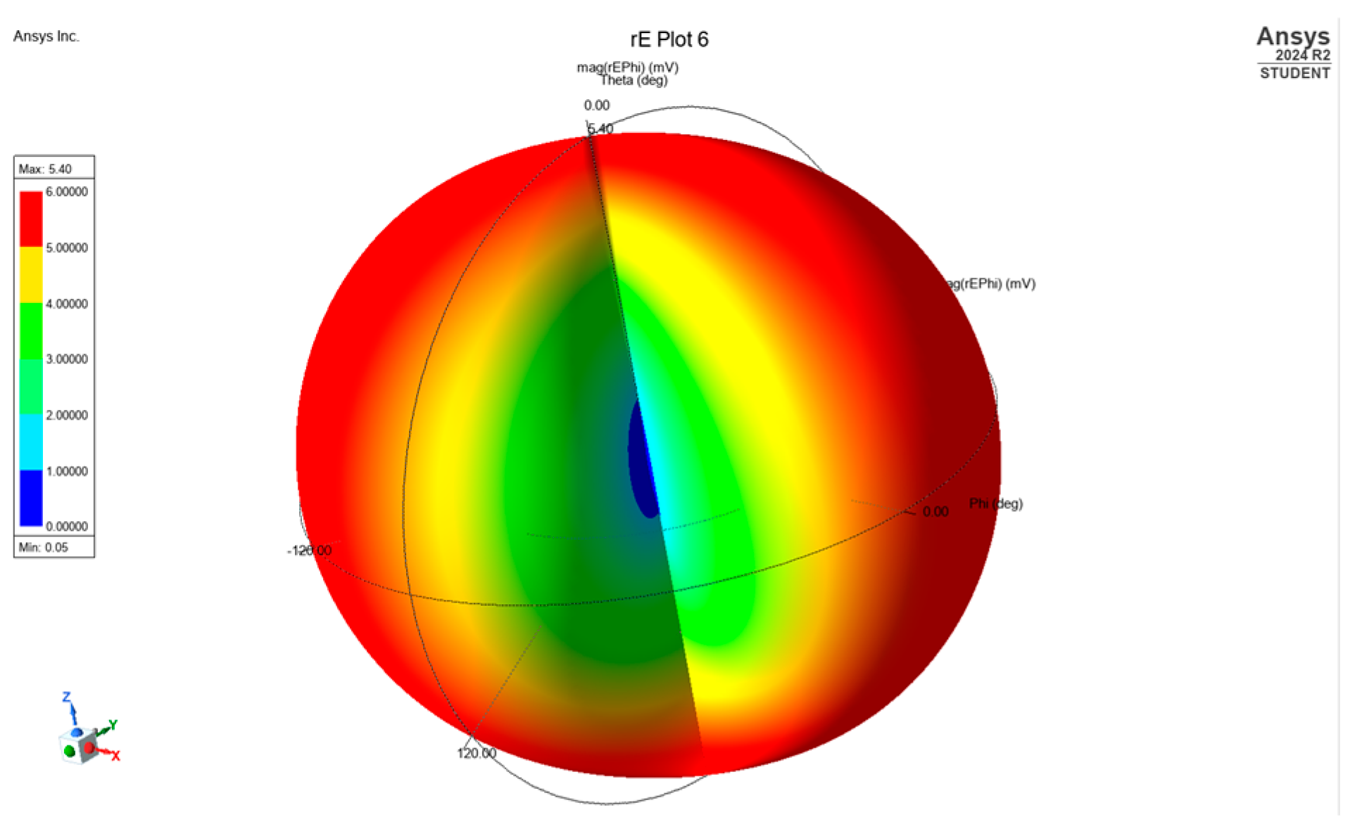
For the sampling frequency of 35 MHz in determining the polarization of the antenna designed, the phase of the electric field was detected from the left and right directions of the antenna with a magnitude of the radiation at 5.4. The state of polarization and orientation in this sample frequency, referred to as the phase in “Phi”, is observed and simulated in a 3D polar plot (
Figure 5).
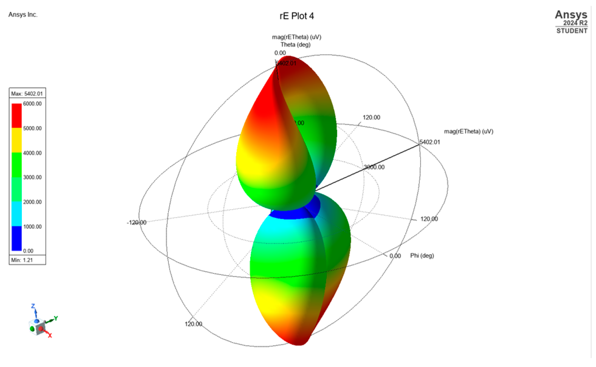
The same sample frequency was used, and the phase of the electric field is observed in Theta. In contrast to the previous 3D polar plot, the phase of Phi was completely out of phase from the state of Theta. The magnitude was higher, about 5402.1. Given this data, when two radial fields had out-of-phase angle coordinates and magnitude in a circular polarization (
Figure 6).
3.3. Interference Tests
Table 1 shows the five test results at different frequencies radiated directly to the radio. Ranges near and after the station’s frequencies were determined to explore how powerful the interference caused by the antenna was.
Table 1 shows the actual interference result to an FM radio as the target device. For trial 1, the FM radio was set to 91.5 MHz, the Win Radio station, as the signal to be received. The distance of the FM radio from the patch antenna was 7.5 m away for trials 1 to 5 (tested inside the laboratory), and the patch antenna radiates at 91.2−91.6 MHz directly at the FM radio. The FM radio was disrupted within the frequency of 91.2−91.6 MHz. The actual frequency response of the FM radio was shown on the spectrum analyzer image. The same settings were applied to trials 2 to 5, but with a varying frequency to stations 94.7 Mellow FM with 94.4–94.9 MHz as its disrupting frequency range, 96.3 Easy Rock with 96.1–96.5 MHz disrupting frequency, 101.1 Yes FM with 100.9–101.2 MHz as disrupting frequencies, and lastly 102.7 Star FM, which is disrupted by 2.4–102.9 MHz.
4. Conclusions
The designed and fabricated antenna with an operating band of 35–4.4 GHz and utilizing frequencies from 91.2 to 102.9 MHz generated by ADF 4351. The antenna successfully interfered with the radio operation. To have an effective intentional destructive interference, the signal must be amplified, and the gain of the antenna must be prioritized during the design. Polarization is important to effectively interfere with and match with receiving antennas or oscillating components. Moreover, the patch antenna has a circular polarization, while the radio has a telescopic antenna. There is a polarization mismatch and reduced efficiency received by the radio because it is linearly polarized. Despite this, the frequency transmitted is tuned within the detection range of the telescopic antenna, and the signal is also strong. Though there is a polarization mismatch and loss, it is possible to cause interference with enough signal power alone using circular polarization to a receiver with a different polarization.
Author Contributions
Conceptualization, J.J.O.G., J.D.L. and J.C.D.C.; methodology, J.J.O.G., J.D.L. and J.C.D.C.; software simulations, J.J.O.G., J.D.L. and J.C.D.C.; validation, J.J.O.G., J.D.L. and J.C.D.C.; Observations and analysis, J.J.O.G., J.D.L. and J.C.D.C.; experimentation and prototype testing, J.J.O.G., J.D.L. and J.C.D.C.; tools and resources, J.J.O.G., J.D.L., and J.C.D.C.; data curation, J.J.O.G., J.D.L. and J.C.D.C.; writing—original draft preparation, J.J.O.G., J.D.L. and J.C.D.C.; writing—review and editing, J.J.O.G., J.D.L. and J.C.D.C.; visualization, J.J.O.G., J.D.L. and J.C.D.C.; All authors have read and agreed to the published version of the manuscript.
Funding
This research received no external funding, and was personally funded by the authors.
Institutional Review Board Statement
Not applicable.
Informed Consent Statement
Not applicable.
Data Availability Statement
Conflicts of Interest
The authors declare no conflict of interest.
References
- Nagrial, M.H.; Hellany, A. EMI/EMC Issues in Switch Mode Power Supplies (SMPS). In EMC York 99. International Conference and Exhibition on Electronic Compatibility. 1999, pp. 180–185. Available online: https://digital-library.theiet.org/doi/10.1049/cp%3A19990266?doi=10.1049%2Fcp%3A19990266 (accessed on 12 April 2024).
- Kaur, M.; Kakar, S.; Mandal, D. Electromagnetic interference. In Proceedings of the 2011 3rd International Conference on Electronics Computer Technology, Kanyakumari, India, 8–10 April 2011; pp. 1–5. [Google Scholar] [CrossRef]
- Jiang, X.; Zhang, S.; Xiao, D.; Liu, S. Mitigating Camera Interference Arising From RF High Transmit Power: The Role of Common Mode Filters and Receiver Compensation Techniques. IEEE Access 2024, 12, 66765–66772. [Google Scholar] [CrossRef]
- Cruz, J.C.D.; Ballado, A.H.; Valiente, F.L.; Lubrin, M.L.M.; Matoza, K.N.D.; Pineda, J.C.; Polancos, A.M. Design of microstrip TV antenna for in-campus digital broadcast system at 479 MHz. In Proceedings of the 2016 IEEE Region 10 Conference (TENCON), Singapore, 22–25 November 2016; pp. 1560–1564. [Google Scholar] [CrossRef]
- Peterson, Z. Build Your Own Patch Antenna for Your Next PCB. Altium, 19-Nov-2022. Available online: https://resources.altium.com/p/build-your-own-patch-antenna-for-your-next-pcb (accessed on 12 April 2024).
- Miron, D.B. Receiving antennas. In Small Antenna Design; Elsevier: Amsterdam, The Netherlands, 2006; pp. 211–233. [Google Scholar] [CrossRef]
- Kaschel, H.; Ahumada, C. Design of Rectangular Microstrip Patch Antenna for 2.4 GHz applied a WBAN. In Proceedings of the 2018 IEEE International Conference on Automation/XXIII Congress of the Chilean Association of Automatic Control (ICA-ACCA), Concepcion, Chile, 17–19 October 2018; pp. 1–6. [Google Scholar] [CrossRef]
- Ballado, A.H.; Cruz, J.D.; Sejera, M.P.; Ingco, W.M.; Juan, C.M.; Nanao, D.N.; Navarro, J.A. Design of indoor microstrip TV antenna for integrated services digital broadcast—Terrestrial (ISDB-T) signal reception at 677 MHz. In Proceedings of the 2014 International Conference on Humanoid, Nanotechnology, Information Technology, Communication and Control, Environment and Management (HNICEM), Palawan, Philippines,, 12–16 November 2014; pp. 1–6. [Google Scholar] [CrossRef]
| Disclaimer/Publisher’s Note: The statements, opinions and data contained in all publications are solely those of the individual author(s) and contributor(s) and not of MDPI and/or the editor(s). MDPI and/or the editor(s) disclaim responsibility for any injury to people or property resulting from any ideas, methods, instructions or products referred to in the content. |
© 2025 by the authors. Licensee MDPI, Basel, Switzerland. This article is an open access article distributed under the terms and conditions of the Creative Commons Attribution (CC BY) license (https://creativecommons.org/licenses/by/4.0/).


