1. Introduction
Recent research indicates that hydrogen-powered propulsion will drive electrification in various transportation sectors. However, due to its low volumetric energy density, the hydrogen must be stored in liquefied form to guarantee the necessary quantity of fuel within limited storage spaces, and due to its low evaporation temperature, it must be isolated effectively from the external environment. In this context, the H2ELIOS project is working to develop a lightweight, innovative, and efficient LH2 aircraft storage prototype, ready to be integrated into the aircraft architecture for flight demonstrations at later stages.
Numerical simulations are essential tools for studying fundamental concepts in this field, encompassing both low- and high-order models. Regarding high-order approaches, i.e., CFD, consolidated models are already available in the most common simulation packages (Fluent/CFX, Star-CCM, or OpenFOAM) to analyze boiling flow phenomena and conjugate heat transfer. Phase-change CFD models are used in several works regarding cryogenic tanks, such as Jeon et al. [
1] and Jiang et al. [
2]; however, their computational cost limits interest in their application for the analysis of long-term scenarios, like flight duration or ground operations of an airplane. On the other hand, 0D models, in particular those considering non-equilibrium conditions in the vapor–liquid mixture, have been selected as the most appropriate tools for simulating long scenarios (in the order of hours) in cryogenic tanks (Al Ghafri et al. [
3], Pérez et al. [
4], Petitpas [
5]).
The HELIOS project aims to develop a DTwin as a key tool for studying fundamental concepts and more complex scenarios, such as highly variable conditions in terms of pressure, temperature, and sloshing effects, triggering drastic evaporation and condensation processes. As an industrial design tool, a DTwin must efficiently manage computational resources to provide accurate results within a limited timeframe. Therefore, both low- and high-fidelity simulation models are required. Considering this point and the fact that the liquid–vapor two-phase flow CFD solvers still require massive computational effort, particularly for large transients such as those involved in a flight mission (order of hours), the analysis for the H2 domain is performed by a non-equilibrium 0D model. Meanwhile, different multi-level models are proposed for calculating insulation gains. They can result in efficient calculations: from a 0D steady heat conduction multilayer approach (considering the liquid level and cylindric and spheric zones) to the use of CFD to solve the 3D transient heat transfer (capturing the thermal inertia transient effects in the tank).
In this work, the DTwin developed as part of HELIOS is presented. First, a detailed description of the numerical models involved is reported, focusing on two main alternatives, the 0D-DTwin and the 3D-DTwin. Finally, results from a standard configuration are reported to showcase its potential and the outputs achievable with the DTwin.
2. Methodology
In the DTwin developed in the current work, a non-equilibrium 0D model performs the analysis for the H2 domain, while for the calculation of insulation gains, different multi-level models are proposed:
0D-DTwin: 0D steady heat conduction multilayer approach (considering the liquid level and cylindric and spheric zones)—coupled to the 0D two-phase thermodynamic H2 model.
3D-DTwin: 3D transient heat conduction, able to capture the thermal inertia transient effects in the tank—coupled to the 0D two-phase thermodynamic H2 model.
Both codes are developed in Python (
https://www.python.org/). The subsection below introduces the 0D thermodynamic model for the two-phase H
2 storage and the strategy for the 3D approach implementations.
2.1. 0D Two-Phase Thermodynamic Model
The 0D non-equilibrium model starts from an approach similar to the work from Al Ghafri et al. [
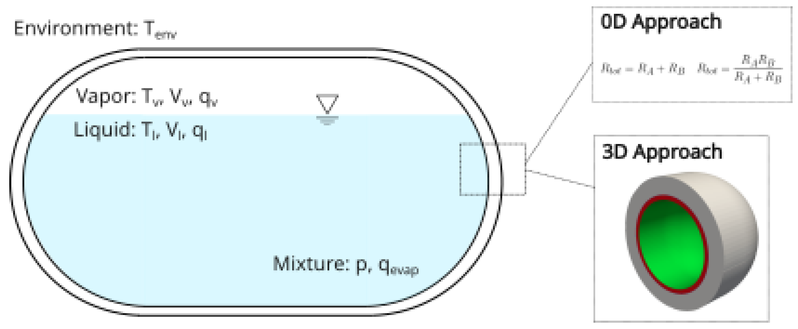
3]. The model considers the vapor and the liquid separately as two control volumes linked by the interface conditions—see the sketch in
Figure 1—interacting with charging (refueling) and discharging (consumption or venting) mass flows. Heat transfer from the insulation and thermal bridges (evaluated from 3D local simulations), as well as potential electric heaters in the liquid domain, are considered. The thermal properties are integrated through NIST-REFPROP [
6] for H2 (function of T and P) and via dedicated functions for the solids.
The heat transfer from the walls is modelled by using empirical pool boiling and natural convection correlations. The liquid–vapor interface heat transfer has been calculated by a dedicated physics-based buoyancy corrected correlation and calibrated against a wide databank of dormancy cases available in the literature (e.g., Aydellot [
7], Hasan et al. [
8]).
With the objective to deal with extended scenarios beyond dormancy, the model incorporates some additional features. The first is the volumetric evaporation, which has been tackled by using a thermodynamic model and with the help of the metastable properties calculation mode available in NIST-REFPROP. Once the liquid achieves saturation conditions, it starts to boil volumetrically instead of only at the surface, just as occurs during subcooling. The same model is crucial to deal with sudden expansion situations where the fluid becomes superheated and reaches saturation after a volumetric boiling. Another relevant submodel has been added to deal with mixing events like shaking-related thermal sloshing (Grotle and Aesoy [
9]), using the modification of the interface heat transfer conditions to replicate the mixing behaviour and its impact on liquid and vapor temperature and pressure.
The set-up of missions with particular mass flows of charge/discharge/venting flows and pressure control logics allow for a detailed description of all variables involved across the scenarios: pressure and temperatures, heat fluxes, mass flows, liquid volume fraction, etc.
2.2. 3D-DTwin
Regarding the 3D approach of the DTwin framework, the chtMultiRegionFoam solver from the open-source software suite OpenFOAM [
10] is employed to perform detailed thermal simulations. This solver is suited for capturing complex thermal behavior, such as thermal inertia effects, thermal gradients, and thermal bridging across the tank’s solid envelope. To enable dynamic, real-time communication between the 0D non-equilibrium model and the 3D thermal model, the ExternalCoupled boundary conditions in OpenFOAM are implemented. Hence, bidirectional data exchange is present, ensuring that phase change interactions and level predictions influence, and are influenced by, the 3D thermal simulations.
This bidirectional coupling requires a robust interface for real-time model communication and precise data synchronization to accurately simulate the tank’s behavior under various scenarios. To achieve this, a custom API was developed using the PyFoam Python library. The API allows seamless interaction between OpenFOAM and the Python environment, creating a flexible bridge that synchronizes data flows between application users and the 0D and 3D modules.
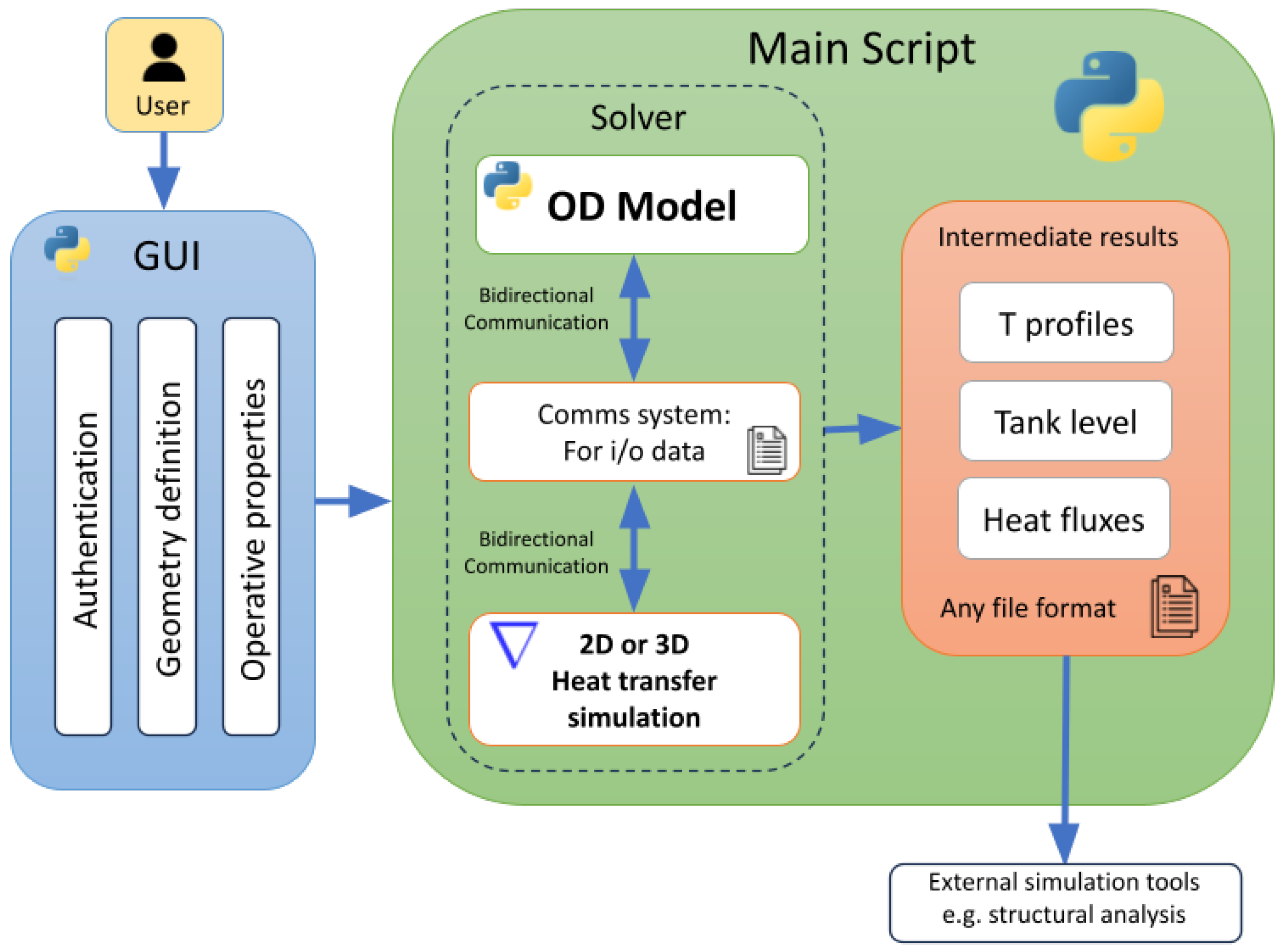
The Python-based API is supervised by a master script, which manages the bidirectional data transfer and oversees the simulation workflow by handling the tank’s initiation, supervision, and termination of different operational scenarios. Moreover, this main script coordinates the output/result delivery system, which gathers simulation results from both models and prepares them for user analysis or external software applications.
This implementation is modular and extendable, meaning it has been designed to accommodate future expansions with minimal adjustments. For instance, additional modules could easily be integrated for complex simulation scenarios or a Graphical User Interface (GUI) to enhance user interaction with the DTwin. Designed for cross-platform compatibility, this tool operates seamlessly on Windows and Linux environments, broadening its accessibility into various research and industrial settings. Furthermore, its outputs are not limited to the digital twin framework itself; they are compatible with other engineering software, such as structural Finite Element Method (FEM) analysis programs.
Figure 2 presents an overview of the DTwin workflow, including the interaction between the 0D and 3D modules and the main script’s supervisory role.
3. Results
As mentioned in
Section 2.2, the DTwin is prepared to simulate different scenarios. Up to this stage, particular attention has been devoted to dormancy and venting analyses. The current section shows results obtained with the 0D and 3D approaches.
3.1. 0D Approach: Dormancy and Venting Case
In this case, the tank envelope is modeled as a multi-layer 0D thermal resistance, thus not considering thermal inertia and 3D effects. Heat transfer occurs with an external environment at a fixed (environment) temperature. Even simplified, the solid envelope module differentiates between the cylindrical core and the spherical domes, and within them between liquid and vapor zones depending on the liquid level at each time step. Any combination of materials and layers can be simulated considering their dependency on temperature and pressure (as the case may be, with average values). The temperatures of each layer are also reported to check if they are within the expected operating range.
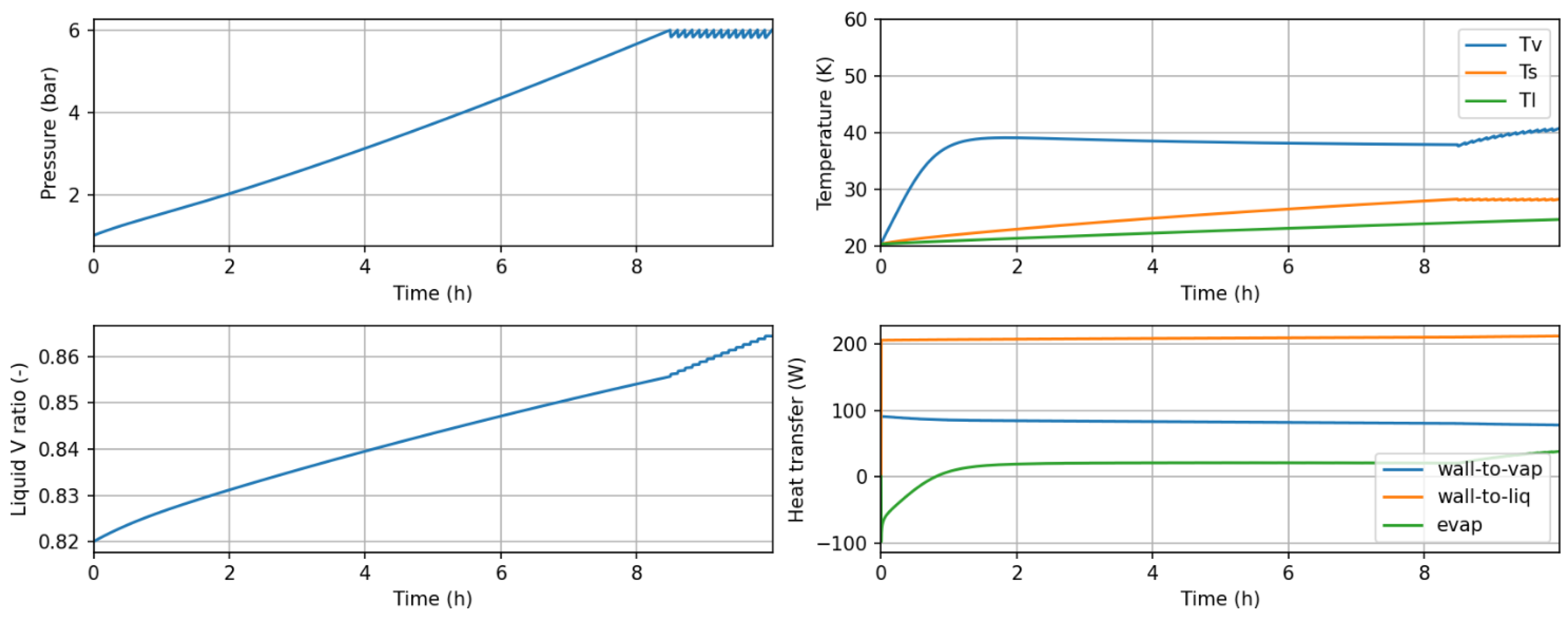
The results, reported in
Figure 3, are related to the 0D two-phase thermodynamic model, providing the transient evolution of thermodynamic variables during a 10 h period, representative of a dormancy plus venting scenario. The initial conditions in this case are considered of equilibrium at 1 bar.
The top-left plot shows how the pressure rises approximately during the first 8.2 h due to the evaporation of liquid H2 and the heating of the vapor. As the pressure reaches its design limit, the dormancy time is determined, and some vapor flow is released (vented) to avoid further pressurization. At the current level of DTwin development, the valves have been modeled as classical compressible valves, fixing an orifice area capable of dealing with the venting flow of each particular tank. The control is just ON–OFF based on a pressure operating range. In the future, more detailed valve models and control laws can be integrated to increase the representativeness of the cases.
The top-right temperature plot depicts the evolution of vapor, liquid, and saturation temperature values. The saturation temperature obviously replicates the pressure profile, as they are thermodynamically related. Conversely, the vapor temperature shows a quick separation from the initial equilibrium, showing the superheating observed by different authors, confirming the non-equilibrium in the tank. On the same line but with higher thermal inertia, the liquid temperature is not able to follow the increase in the saturation temperature, thus revealing an increased subcooling level. When venting starts, the temperature of the liquid continue to rise, eventually equalizing the saturation one, where a more intense volumetric boiling would start (incoming energy no longer dedicated to heat the liquid but only to vaporize).
Continuing in the same figure (bottom-left), we observe the liquid expansion effect with time, well reported as well as something to carefully consider when identifying the filling level of a tank. As the liquid is heated, it reduces its density and expands, resulting in an increased liquid volume ratio. Finally, some figures of the involved heat transfer rates are given (bottom-right), showing that in this case, due to the higher volume fraction occupied and its lower temperature, the liquid heat transfer is the dominant one. The shown outputs can be extended with many other values, like variations in phase masses, interface heat/mass interactions, temperatures at points of interest, etc.
3.2. 3D Approach: Dormancy Case
For this analysis, the solid envelope is simulated using the CFD solver, delivering a detailed temperature map across the layers and evaluating key thermal parameters, such as heat transfer rates and energy parameters.
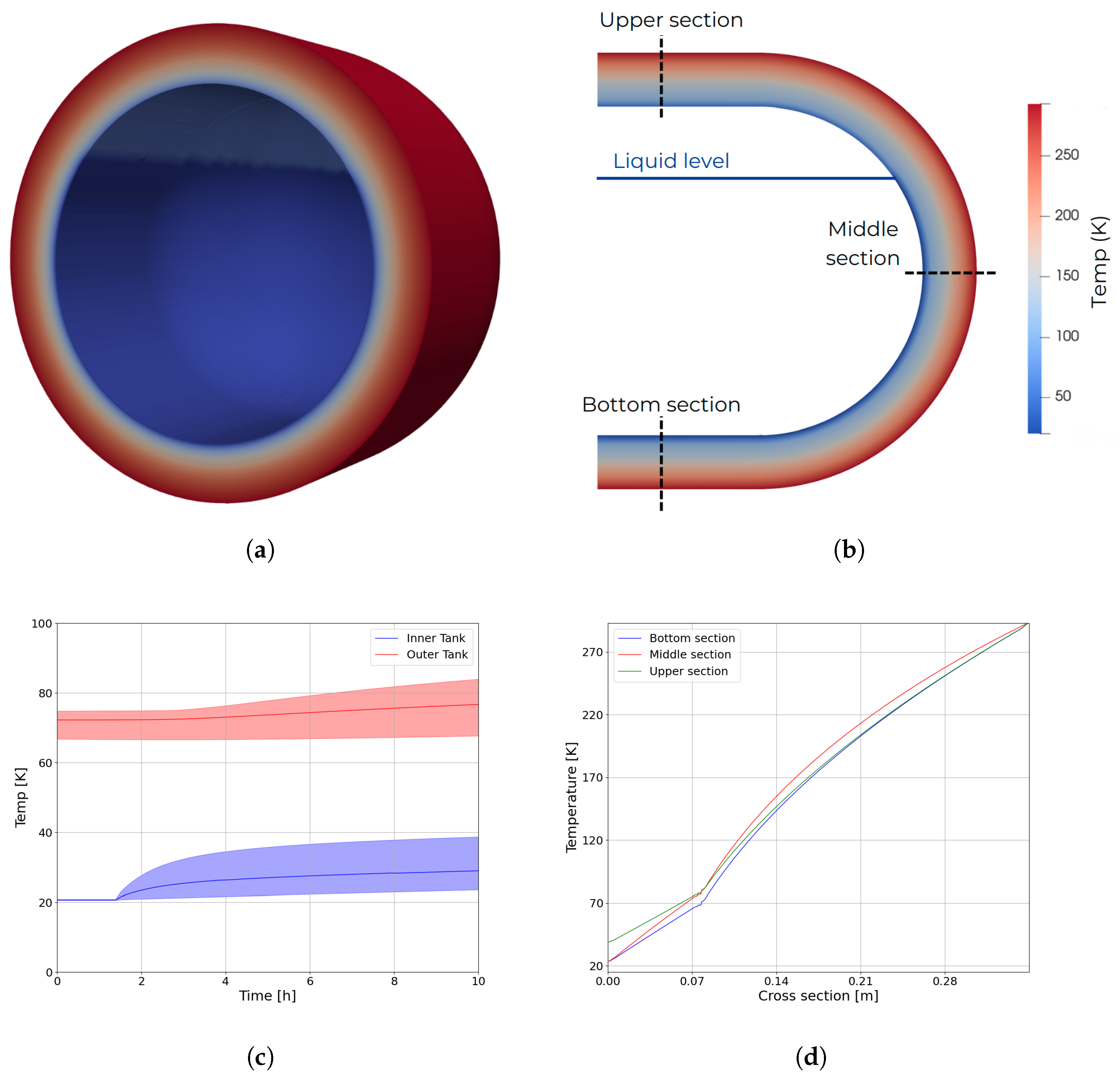
Figure 4a shows an example of a 3D temperature map obtained in simulations, while the section view in
Figure 4b shows the liquid level and the different temperature profiles collected. The simulation relies on a coupled approach between the 0D and CFD modules. Therefore, the 0D model receives a heat flux from the inner wall of the tank and calculates the hydrogen temperatures in the vapor (
) and liquid (
) phases, as well as the tank inner pressure and liquid level. In return, the CFD model receives the 0D-derived temperature distribution in the inner wall and calculates system heat fluxes and a precise temperature profile across tank walls. The coupling between the two modules is purely explicit, and the time-step is set between 1 to 5 s. On a global scale, the simulation time does not exceed the duration of the physical time.
Figure 4c depicts the results for the test case, showing the evolution of temperatures within the inner tank (including average temperature and variations) and the outer tank. To enhance model stability, an initial phase is employed where the internal wall temperatures are held constant while the 0D model remains inactive. This step mitigates the risk of abrupt temperature gradients and excessive heat fluxes, which could otherwise destabilize the thermodynamic model. When the system reaches a steady state scenario (approximately at 1.5 h in simulation time), the 0D model is activated; at this point, the average temperature in the inner tank begins to rise, driven by higher temperatures of the vapor phase that increases the system boil-off leading to a gradual tank pressurization with consequent incremental in saturation temperature within the tank. Temperature profiles for the selected cross-sections are reported in
Figure 4d, highlighting the slight differences at different locations within the tank. These differences emphasize the spatial thermal heterogeneity that can arise during operational conditions.
4. Conclusions
This work presents the current stage of development of a new DTwin model for LH2 aircraft storage tanks. The model structure and approach is given, highlighting the use of a 0D non-equilibrium model for the fluid and the combination of a 0D steady multilayer and 3D CFD unsteady model for the solid tanks and insulations. The programming strategy for the latter is also explained, coupling OpenFoam with the 0D model through a master Python code.
Some illustrative results are given for both options to show the potential of the DTwin to provide technological feedback in the tank design process, e.g., in the selection of insulation material, tank sizes, and layer thicknesses. In the next steps of the project, an extension to other scenarios is expected, for a later direct comparison with the results obtained on an experimental demonstrator.
Author Contributions
Conceptualization, methodology, writing—original draft preparation, software: C.O., E.S. and M.M.-O.; writing—review and editing, supervision: A.A., J.C. and J.R.; project administration and funding acquisition: J.C. and J.R. All authors have read and agreed to the published version of the manuscript.
Funding
This research was conducted under
HydrogEn Lightweight & Innovative tank for zerOemisSion aircraft (H2ELIOS)—Clean Aviation research project Ref. 101102003 (
https://h2elios.eu/home, accessed on 20 January 2025). The H2ELIOS project is funded by the European Union and supported by the Clean Aviation Joint Undertaking and its members. Disclaimer: The contents presented in this article reflect only the authors’ point of view: the authors and Clean Aviation are not responsible for any use that may be made of the information this paper contains. Again, views and opinions expressed are, however, those of the authors only and do not necessarily reflect those of the European Union or Clean Aviation Joint Undertaking. Neither the European Union nor the granting authority can be held responsible for them.
![Engproc 90 00097 i001]()
Institutional Review Board Statement
Not applicable.
Informed Consent Statement
Not applicable.
Data Availability Statement
Data are contained within the article.
Acknowledgments
Carles Oliet, as a Serra Húnter Associate Professor, acknowledges the Catalan Government for their support through the relevant program. Marcial Mosqueda-Otero is supported by the Catalan Agency for Management of University and Research Grants (2024 FI-1 00684).
Conflicts of Interest
The authors declare no conflicts of interest.
Abbreviations
The following abbreviations are used in this manuscript:
| DTwin | Digital Twin |
| LH2 | Liquid Hydrogen |
| API | Application Programming Interface |
References
- Jeon, G.M.; Park, J.C.; Choi, S. Multiphase-thermal simulation on BOG/BOR estimation due to phase change in cryogenic liquid storage tanks. Appl. Therm. Eng. 2021, 184, 116264. [Google Scholar] [CrossRef]
- Jiang, Y.; Yu, Y.; Wang, Z.; Zhang, S.; Cao, J. CFD simulation of heat transfer and phase change characteristics of the cryogenic liquid hydrogen tank under microgravity conditions. Int. J. Hydrogen Energy 2023, 48, 7026–7037. [Google Scholar] [CrossRef]
- Al Ghafri, S.Z.; Swanger, A.; Jusko, V.; Siahvashi, A.; Perez, F.; Johns, M.L.; May, E.F. Modelling of liquid hydrogen boil-off. Energies 2022, 15, 1149. [Google Scholar] [CrossRef]
- Perez, F.; Al Ghafri, S.Z.; Gallagher, L.; Siahvashi, A.; Yonghee, R.; Kim, S.; Kim, S.G.; Johns, M.L.; May, E.F. Measurements of boil-off gas and stratification in cryogenic liquid nitrogen with implications for the storage and transport of liquefied natural gas. Energy 2021, 222, 119853. [Google Scholar] [CrossRef]
- Petitpas, G. Boil-Off Losses Along LH2 Pathway; Technical Report LLNL-TR-750685; Lawrence Livermore National Laboratory: Livermore, CA, USA, 2018. [Google Scholar]
- Lemmon, E.W.; Bell, I.H.; Huber, M.; McLinden, M. NIST Standard Reference Database 23: Reference Fluid Thermodynamic and Transport Properties-REFPROP, Version 10.0; Standard Reference Data Program; National Institute of Standards and Technology: Gaithersburg, MD, USA, 2018.
- Aydellot, J.C. Normal Gravity Self-Pressurization of 9-Inch-(23 cm) Diameter Spherical Liquid Hydrogen Tankage; Technical Report TN D-4171; NASA: Washington, DC, USA, 1960. [Google Scholar]
- Hasan, M.M.; Lin, C.; Van Dresar, N. Self-Pressurization of a Flightweight Liquid Hydrogen Storage Tank Subjected to Low Heat Flux; Technical Report Technical Memorandum 103804; NASA: Washington, DC, USA, 1991. [Google Scholar]
- Grotle, E.; Aesoy, V. Numerical Simulations of Sloshing and the Thermodynamic Response Due to Mixing. Energies 2017, 10, 1338. [Google Scholar] [CrossRef]
- Weller, H.G.; Tabor, G.; Jasak, H.; Fureby, C. A tensorial approach to computational continuum mechanics using object-oriented techniques. Comput. Phys. 1998, 12, 620–631. [Google Scholar] [CrossRef]
| Disclaimer/Publisher’s Note: The statements, opinions and data contained in all publications are solely those of the individual author(s) and contributor(s) and not of MDPI and/or the editor(s). MDPI and/or the editor(s) disclaim responsibility for any injury to people or property resulting from any ideas, methods, instructions or products referred to in the content. |
© 2025 by the authors. Licensee MDPI, Basel, Switzerland. This article is an open access article distributed under the terms and conditions of the Creative Commons Attribution (CC BY) license (https://creativecommons.org/licenses/by/4.0/).


 ,
, 