Abstract
Foldable wing designs are becoming increasingly popular due to their advantages in the rapid deployment and compact packaging of fixed-wing UAVs, particularly when compared to horizontal take-off and VTOL counterparts. However, selecting an appropriate wing design requires the careful consideration of aerodynamic performance and volume storage constraints. As a result, a trade-off between performance and practicality must be addressed during the conceptual design phase. The primary objective of this study is to identify the optimal wing configuration for a tube-launched foldable wing design. To achieve this, the analysis combine an in-house design tool developed in Excel and XFLR5 v7.01 software.
1. Introduction
Foldable-wing-design UAVs, such as loitering munitions [1], are becoming increasingly popular due to their ease of transportation, compatibility, and minimal operator training required during critical flight phases like take-off. However, specific design considerations must be addressed, particularly regarding the frame’s surfaces, such as the main wing, which must fit within or attach to the fuselage. Additionally, aerodynamic factors like the Reynolds number (below 300,000), which relates to fluid viscosity, play a critical role. In this study, a two-stage analysis is conducted for a given mission profile and selected weight during the conceptual design phase. First, the weight is expressed as a ratio with power (W/P) and surface area (W/S), ensuring that the designed platform meets all performance requirements for key flight attitudes, including stall, cruise, maneuvering, rate of climb, and climb gradient. This stage identifies the acceptable wing area which the designer uses as the basis for the second phase: wing analysis. The airfoil selection stage is streamlined to allow a wide range of Reynolds numbers, enabling the testing of various airfoils using XFLR5 software. The final wing design is selected to meet the desired lift characteristics and achieve an elliptical lift distribution. Lifting-Line Theory (LLT) is applied and compared with LLT and panel methods in XFLR5 for validation. To support rapid and efficient decision-making, the entire design process is automated in Excel using a flow-diagram-like approach inspired by D.P. Raymer [2]. This study represents a key step in the preliminary design of a foldable-wing electric UAV.
2. Concept of Operations—Mission Profile
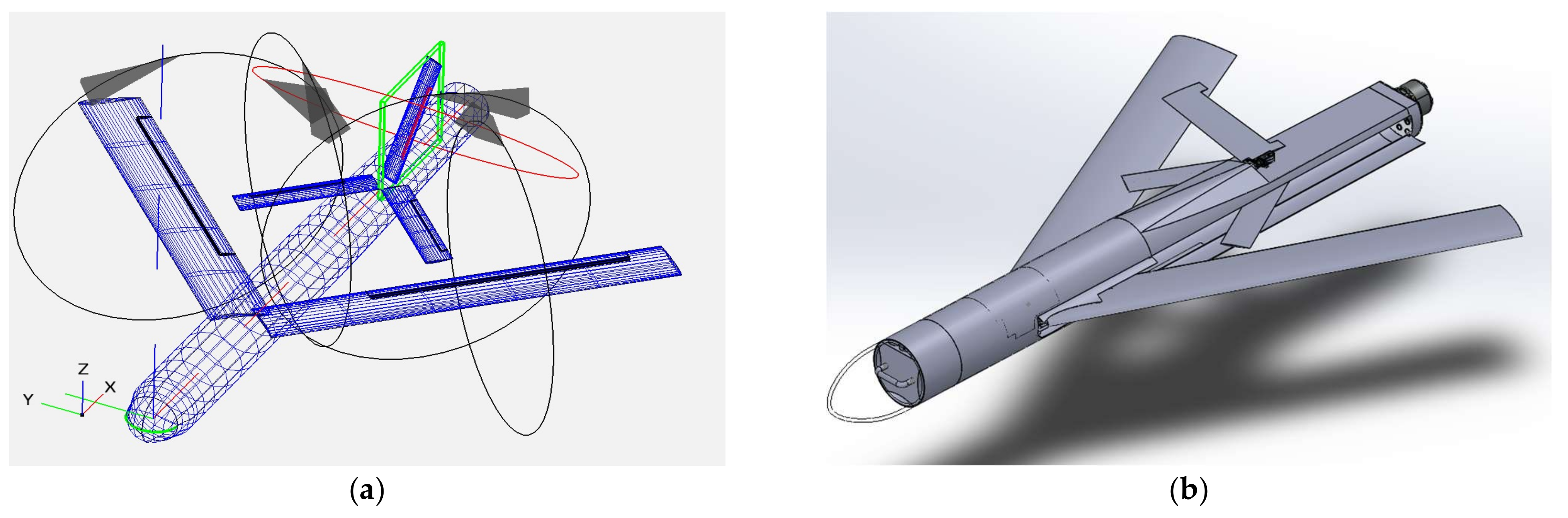
The presented analysis was conducted with the objective of defining the specific requirements for an electric Class I UAV [3] designed for intelligence, reconnaissance, and surveillance (ISR) missions, as depicted in Figure 1. The primary characteristics of the design are flexibility and compatibility, enabling operation by a small team of one or two personnel.

Figure 1.
Different design stages of the presented UAV. (a) Initial sketch. (b) Conceptual design.
The tube-based design was developed to ensure convenient storage and rapid deployment to the area of interest. A foldable mid-wing configuration, designed to fit inside the fuselage, allows the use of a cylindrical tube barrel. This design choice reduces aerodynamic form drag while maximizing surface area. Additionally, cylindrical barrels are commonly employed in small launchers, particularly in defense applications, offering significant advantages over square cross-section fuselages. These advantages extend to both low and high foldable wing methods, such as those used in the Hero series and Switchblade UAS.
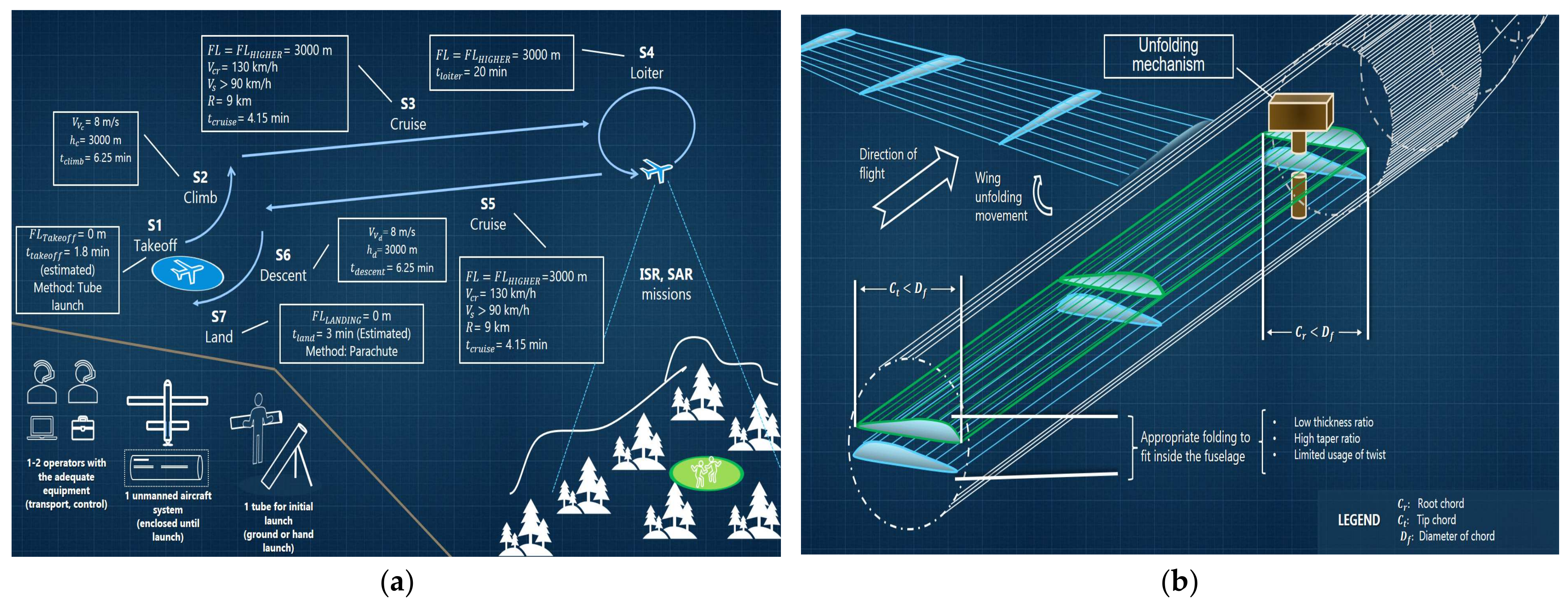
Considering the preceding analysis, the wing design can be distilled into four principal considerations (Figure 2):
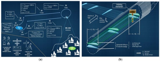
Figure 2.
(a) Mission profile. (b) Unfolding wing concept (non-dimensioned).
- A wing with a tip Ct and root chord Cr lower than the diameter Df of the fuselage must be used.
- The usage of any form of twist at (aerodynamic and geometric) should be reduced. Thus, more space for the vital subsystems will be saved.
- Non-parallel wing folding is applicable for maximum surface area S with different pivot points for each semi-span.
- The total wing semi-span b/2 must be less than 1 m.
The following set of requirements were selected following the methodology that is used at [4], as presented to Table 1.

Table 1.
Weights and lift-to-drag ratio of the proposed high-aspect-ratio UAV.
Furthermore, the entire process was developed within an Excel program specifically tailored for electric fixed-wing unmanned aerial systems with propellers. This enables the design team to receive prompt and detailed feedback and, if necessary, revisit and refine the entire design process.
The design program is organized into five distinct categories, separated by a clear upper white line: phase, subphase, step, process, and tables and figures associated with each phase. This structured approach is inspired by project management monitoring methods, such as the Gantt chart. Each logical or numerical value is assigned a unique identifier to ensure clarity and traceability. Phases are numbered from 1 to 1000, subphases are designated with a capital letter (A to Z), and steps are assigned a number between 1 and 1000, each linked to a specific process.
Finally, a color-coding system is implemented to visually distinguish between logical commands, inputs, outputs, and results, as illustrated in Figure 3.
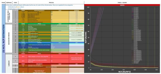
Figure 3.
W/S vs. W/P estimation in Excel environment (retrieved from Excel Program v2).
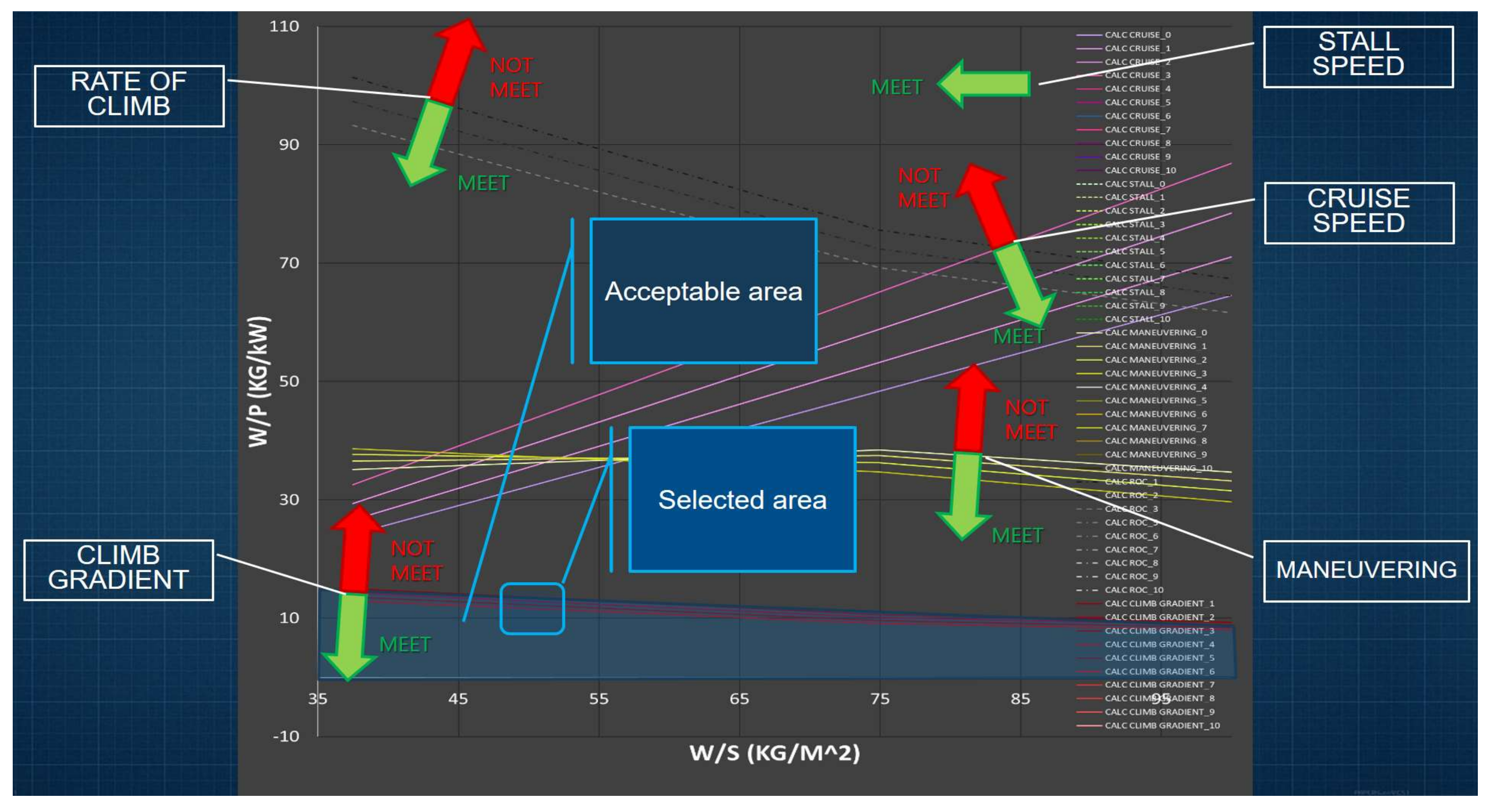
3. W/S vs. W/P Analysis
The weight of the UAV is directly influenced by the surface area and the power required (W/S and W/P matching). The objective is to identify the optimal combination of W/S and W/P by examining five different flight phases: take-off, cruise, and stall speeds; maneuvering; rate of climb; and climb gradient. In [5,6,7], the mathematical proofs of equations are presented and used with a slightly different approach. Moreover, for the purposes of the design, the acceptable load factors adhere to the STANAG airworthiness requirements, as presented in [8], and data for zero drag coefficient are sourced from [9]. Finally, data for international standard conditions (ISA) are used.
The cruise speed criteria are expressed as:
where
Index ratio;
: Ratio between flight leave and sea level.
Similarly, the stall criteria are as follows:
where
Density of air ().
Maneuvering criteria strongly depend on the load factor and subsequently on the adequate thrust-to-weight ratio:
where
e: Oswald constant.
The rate of climb and climb gradient directly depend on the vertical speed; thus, the zero drag coefficient must be as low as possible:
The relevant bibliography defines the optimal area of W/S and W/P as the one that is upright to the diagram. However, to fulfill the special considerations, lower values in the designated area must be used. A high-aspect-ratio design presents a feasible solution. After trial and error, ceilings up to 3000 m with 1000 m pace are examined, and the initial values are and (Figure 4). Thus, this is the design option that will be further examined in the wing design phase. In the next Section, these values are examined in detail.
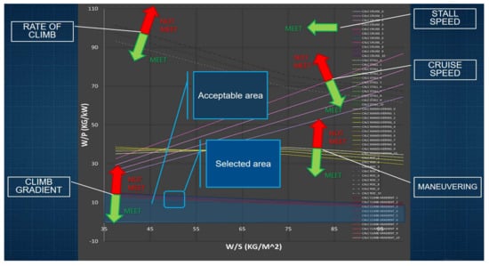
Figure 4.
W/S vs. W/P estimation plot for high aspect ratio (retrieved from Excel Program).
4. Wing Analysis
Wing selection represents a pivotal and intricate stage of the design process, encompassing a multitude of intricate steps. These can be broadly classified into three principal subphases: airfoil selection, which determines the wing’s aerodynamic characteristics; geometry, which defines the final shape and performance of the wing; and lift distribution analysis, which ensures the structure’s rigidity during flight. Therefore, XFLR5 will be employed to obtain precise results.
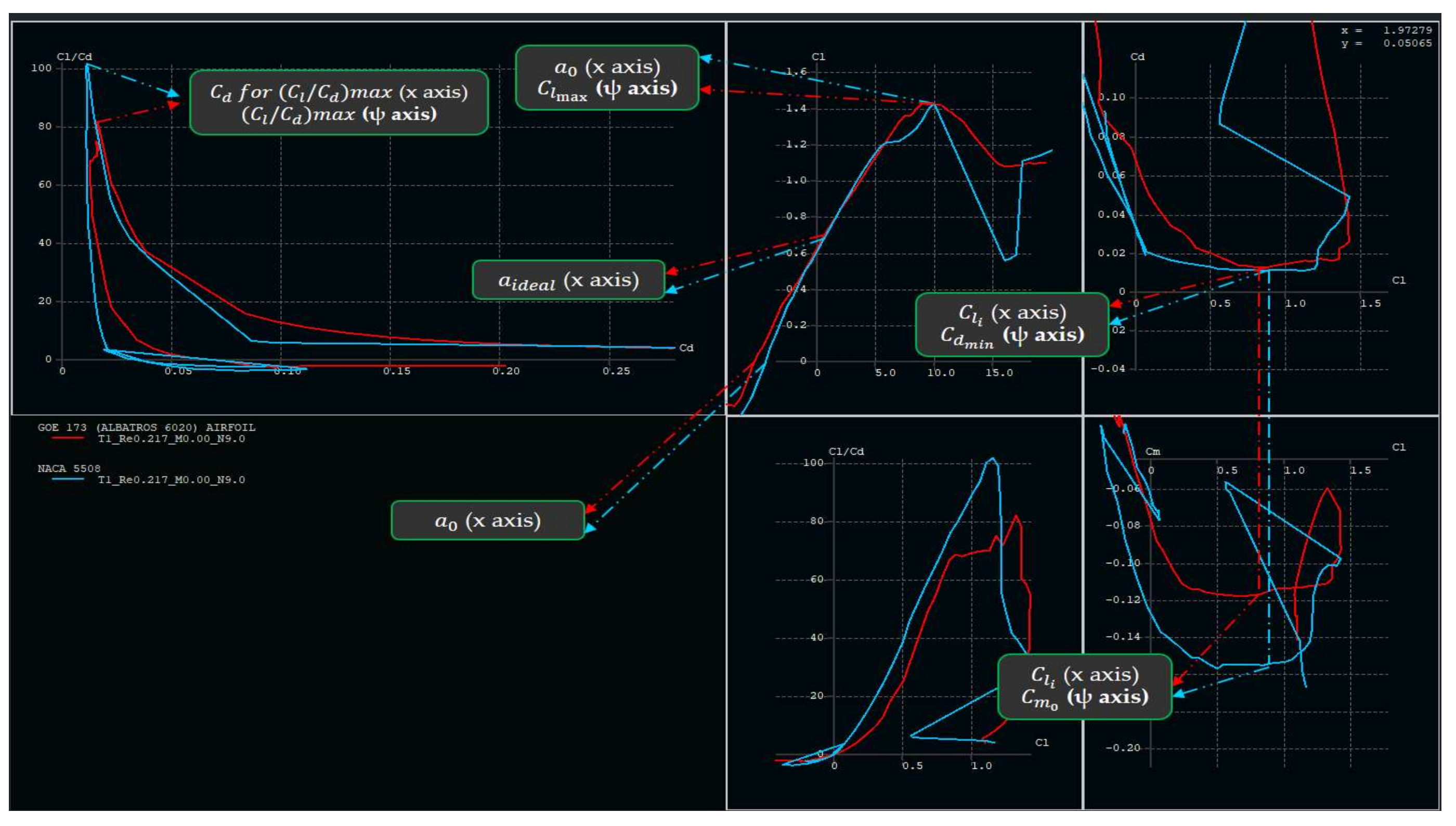
4.1. Airfoil Selection
For an efficient wing design, an adequate airfoil both for max and ideal lift coefficient must be selected. For a level cruise flight, these must be
The maximum lift is achieved near the stall speed. Thus:
Also, the Reynolds number is given by the following equation:
where
The dynamic viscosity of the fluid ().
: The surface area ().
: The mean aerodynamic chord ().
Finally, the surface area, wingspan, and mean aerodynamic chord are expressed as follows:
The precise determination of W/S and W/P will be made in accordance with and at the desired cruise altitude, which is 1000 m. Table 2 presents a more comprehensive analysis of the selected values from Figure 2. A series of trials was conducted with a variety of NACA, GOE, ELLPER and FX series airfoils, utilizing XFLR5 software, with the objective of identifying the optimal option for an Re range of 215,000 to 226,000. Of the two candidates, NACA 5508 and GOE 173, the latter presents superior characteristics, offering enhanced longitudinal control and endurance due to its high moment coefficient and lift-to-drag ratio. Based on these considerations, the latter option will be selected (Figure 5). Moreover, GOE 173 is a thin, highly cambered airfoil that can be folded into the fuselage, and it is also ideal for use in lightweight construction. The resulting unmanned aircraft will be more controllable and agile, allowing the operator to efficiently recon the desired area.
Table 2.
Lift coefficients for different power and surface loadings.
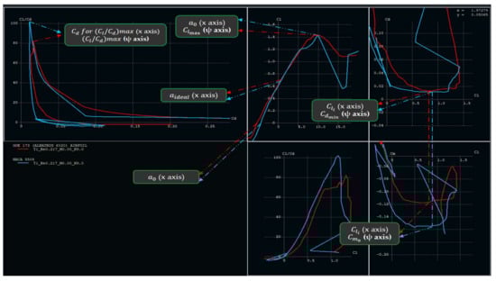
Figure 5.
Aerodynamic characteristics of NACA 5508 and GOE 173 at Re = 216,995 (retrieved from XFLR5). The results are presented in Table A1.
4.2. Wing Configuration Selection
For the purpose of the analysis, six different wing geometry configurations are examined, two untapered, two tapered with no sweep in the middle of the chord (symmetrically tapered), and two tapered with sweep in the middle of the chord (swept tapered wing). The characteristics of each wing option are given by the following set of equations:
where
Taper ratio;
: Sweep of the wing at the leading edge (deg);
: Sweep of the wing at the quarter chord (deg);
: Sweep of the wing at the half chord (deg);
: Root chord (deg);
: Sweep of the wing at the leading edge (deg);
: Sweep of the wing at the leading edge (deg).
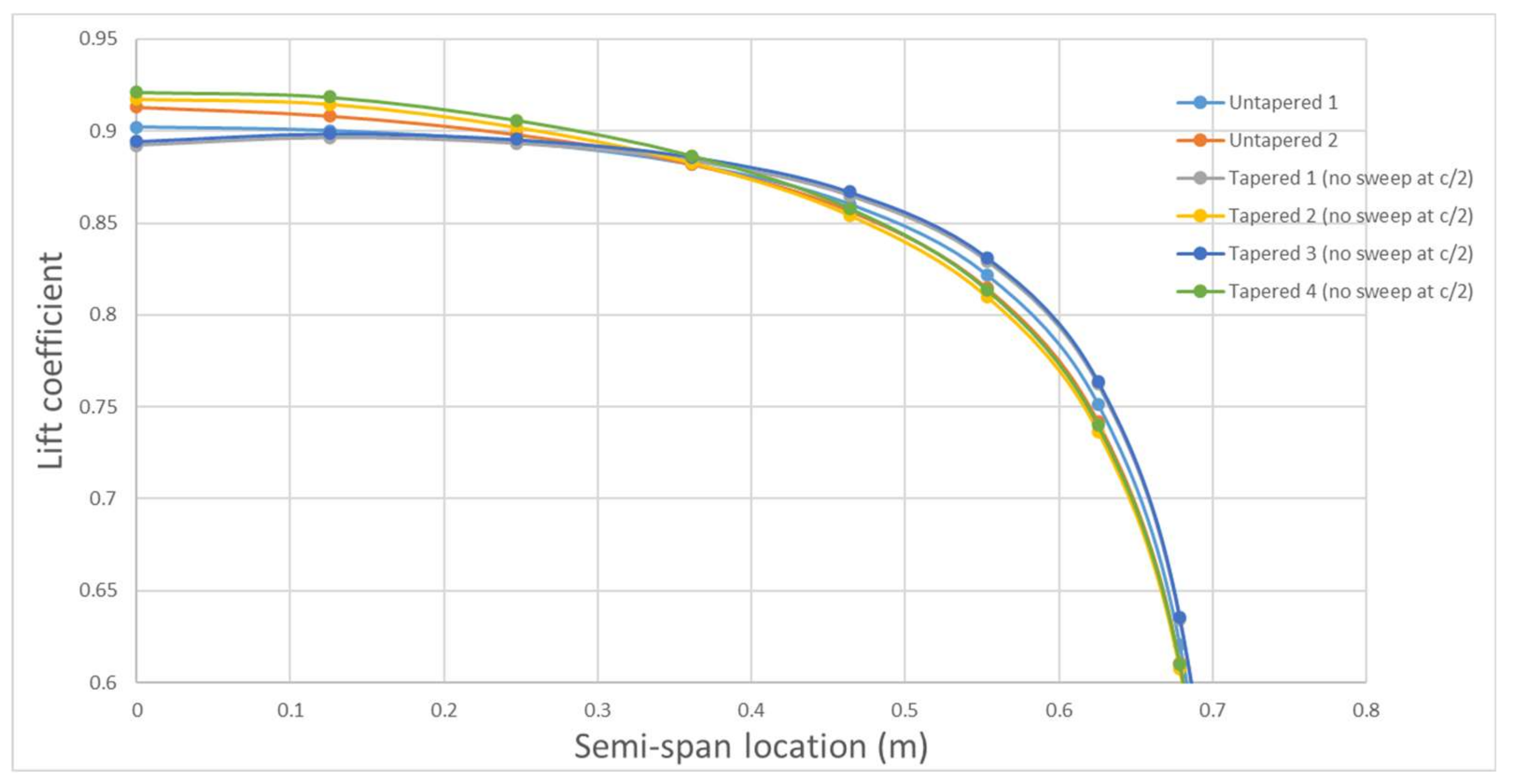
4.3. Lift Distribution Analysis
In addition to geometric characteristics, the distribution of lift is the primary criterion for wing selection. Lifting-Line Theory, as presented in [8] (pp. 242–246), is employed to evaluate and compare the six selected wing designs. Table 3 provides the total calculated lift for each wing, while Figure 4 illustrates the lift distribution along the semi-span.
Table 3.
Wing options for the UAV.
The maximum feasible taper ratio for the design is determined to be λ = 0.91, based on the design requirements and the maximum acceptable chord root value ( = 0.0998). The incidence angle has a dynamic relationship with the twist angle (αt). Incorporating twist improves stall characteristics and results in a more elliptical lift distribution; however, it directly increases the incidence angle, particularly in tapered wing designs. As a result, a trade-off must be made, and an inevitable increase in the incidence angle is selected, which also minimizes the volume occupied within the fuselage.
Furthermore, incorporating sweep without applying a twist angle negatively impacts the lift distribution. Based on these findings, Option 2 appears to be the most suitable for the design requirements, offering an optimal balance between minimal twist usage and superior lift distribution compared to the other options (Figure 6).
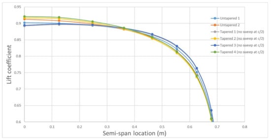
Figure 6.
Lift distribution analysis at the semi-span of six different options.
5. Comparison of Different Lifting Distribution Calculus
The chosen method for calculating wing design provides designers with an initial estimate of the desired design. While the values may be overestimated, they still offer a preliminary approximation of the real values. XFLR5 can be used to gain insight into these differences. When running an analysis in this program for the same selected wing (Option 2), using Lifting Line-Theory (LLT) and Panel, and comparing the results with the presented method, it is evident that smaller incidence angles are required to achieve the ideal lift coefficient. As shown in the lift distribution plot in Figure 7, the first method indicates an angle of attack ranging from −2 to −1.5 degrees (approximately 2.8 to 3.3 degrees of incidence), while the latter indicates an angle of −1.5 to −1 degrees (approximately 3.3 to 3.8 degrees of incidence). The accuracy of our calculation is confirmed by the elliptical form in all theories.
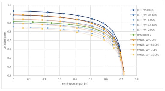
Figure 7.
Lift distribution analysis at the semi-span of the wing.
6. Conclusions
The trade-off between optimal performance and functionality in folding wing design is challenging. However, the presented method can be used as a first step in this direction. In addition, the Excel program provides a quick decision-making platform for designers. A way forward is to analyze more airfoils, such as [10], and different fuselage cross-sections (i.e., square) to compare results with real flight tests.
Author Contributions
Conceptualization, E.K. and E.N.; methodology, E.K.; software, E.K.; validation, E.K.; formal analysis, E.K.; investigation, E.K.; resources, E.K.; data curation, E.K.; writing—original draft preparation, E.K., E.N., A.P. and S.A.; writing—review and editing, E.K., E.N., A.P. and S.A.; visualization, E.K.; supervision, V.L. and V.K.; project administration, E.K., E.N., A.P., V.L. and V.K. All authors have read and agreed to the published version of the manuscript.
Funding
This research received no external funding.
Institutional Review Board Statement
Not applicable.
Informed Consent Statement
Not applicable.
Data Availability Statement
Data are contained within the article.
Conflicts of Interest
The authors declare no conflicts of interest.
Appendix A
Table A1.
Aerodynamic characteristics of NACA 5508 and GOE 173 at Re = 216,995 (cruise state).
Table A1.
Aerodynamic characteristics of NACA 5508 and GOE 173 at Re = 216,995 (cruise state).
| Symbol | Value | NACA 5508 | GOE 173 |
|---|---|---|---|
| Maximum lift coefficient of the airfoil | 1.42635 | 1.42599 | |
| Minimum drag coefficient of the airfoil | 0.01113 | 0.01264 | |
| Moment coefficient of the airfoil | −0.15497 | −0.11613 | |
| Stall angle of the airfoil | 10.00302 | 8.99963 | |
| Zero lift angle of attack of the airfoil | −4.34946 | −5.30782 | |
| Lift-to-drag ratio of the airfoil | 82.01870 | 101.77422 | |
| Ideal lift coefficient | 0.84325 | 0.83762 | |
| Maximum thickness ratio of the airfoil (%*0.01) | 7.8% (at 20% chord) | 8.00% (at 29.03% chord) | |
| Angle of attack that corresponds to the ideal lift coefficient | 0.70494 | 0.7191 | |
| Stall Quality | 1. Sharp 2. Moderate 3. Docile | 1. SHARP (harder to recover from stall-spin) | 2. MODERATE (easier to recover from stall-spin) |
| Slope at C_L VS AoA diagram of the airfoil | 6.0046848 | 6.013728 |
References
- Mark Voskuijl, B. Performance analysis and design of loitering munitions: A comprehensive technical survey of recent developments. Def. Technol. 2022, 18, 325–343. [Google Scholar] [CrossRef]
- Aircraft Design & RDS Website. Available online: http://aircraftdesign.com/ (accessed on 11 July 2024).
- Development Concepts and Doctrine Centre Crown (UK). 0-30.2 (JDP 0-30.2) Unmanned Aircraft Systems. Royal Ministry of Defence (UK). 2017. Available online: https://assets.publishing.service.gov.uk/government/uploads/system/uploads/attachment_data/file/673940/doctrine_uk_uas_jdp_0_30_2.pdf (accessed on 5 May 2024).
- Karatzas, E.; Kostopoulos, V.; Lappas, V. Preliminary weight estimation of canister based light foldable wing electric propulsion UAV, as a platform for swarm applications. In Proceedings of the 12th EASN International Conference on “Innovation in Aviation & Space for Opening New Horizons”, Barcelona, Spain, 18–21 October 2022; Volume 2526. [Google Scholar] [CrossRef]
- Roskam, J. Airplane Design: Preliminary Sizing of Airplanes, Part I; Design Analysis and Research Corporation: Lawrence, KS, USA, 1985; ISBN 1-884885-42-X. [Google Scholar]
- Sadraey, M.H. Aircraft Design. A system Engineering Approach; John Wiley and Sons Ltd.: Chicago, IL, USA, 2013; ISBN 10 9781119953401. [Google Scholar]
- Raymer, D.P. Aircraft Design. A Conceptual Apporach, 6th ed.; American Institute of Aeronautics and Astronautics: Reston, VA, USA, 2018; ISBN 978162410490. [Google Scholar]
- North Antlatic Treaty Organization. STANAG 4703: Light Unmanned Aircraft Systems Airworthines Requirements; NATO Standardization Agency: Brussels, Belgium, 2014. [Google Scholar]
- Abbott, I.H.; Donehoff, V. Theory of Wing Sections; Dover Publications: New York, NY, USA, 1959; ISBN 486-60586-8. [Google Scholar]
- Selig, M.S. The Design of Airfoils at Low Reynolds Numbers. AIAA Paper 85-0074. In Proceedings of the 23rd Aerospace Sciences Meeting, Reno, NV, USA, 14–17 January 1985. [Google Scholar] [CrossRef]


Disclaimer/Publisher’s Note: The statements, opinions and data contained in all publications are solely those of the individual author(s) and contributor(s) and not of MDPI and/or the editor(s). MDPI and/or the editor(s) disclaim responsibility for any injury to people or property resulting from any ideas, methods, instructions or products referred to in the content. |
© 2025 by the authors. Licensee MDPI, Basel, Switzerland. This article is an open access article distributed under the terms and conditions of the Creative Commons Attribution (CC BY) license (https://creativecommons.org/licenses/by/4.0/).