Abstract
The Italian Aerospace Research Centre (CIRA) is developing an unmanned stratospheric platform for Earth observation and telecommunications, known as a High-Altitude Pseudo-Satellite (HAPS). This paper presents an aerodynamic and stability analysis of a new closed-wing HAPS configuration. The design uses a hybrid approach, combining aerodynamic and aerostatic forces to achieve weight balance, with the stability analysis accounting for the buoyancy force applied at the center of volume of the structure. Following the initial design phase, which aims for an altitude of 20 km, a speed of 16 m/s, and a payload capacity of 20 kg, a suitable configuration using a NACA 0018 airfoil is selected. The aircraft lift–drag curve is evaluated using a stationary, incompressible Reynolds-Averaged Navier–Stokes (RANS) analysis with a k- SST turbulence model in OpenFoam. A detailed longitudinal and lateral-directional stability analysis is also conducted using OpenFOam and AVL software.
1. Introduction
The demand for long-endurance unmanned stratospheric platforms for Earth observation and telecommunications (referred to as HAPSs) has surged in recent years. This surge is due to their multiples roles in different scenarios, such as navigation and position location systems, surveillance, remote sensing, environmental monitoring, and emergency communications. Typically, operating at altitudes around 18–20 km, which places them well above commercial air traffic, these platforms benefit from relatively stable weather conditions and consistent temperatures. The interest in HAPSs is due to different factors, such as their ability to sustain their position for an extended duration over a specific area of interest, providing uninterrupted coverage with typical endurance of several months, or their capacity to provide real-time images and video. Moreover, flying at this altitude offers greater proximity to the Earth’s surface, resulting in images with higher spatial resolution compared to satellite images. Another major benefit is represented by their net-zero emissions. The growth of air traffic has led the aviation world to focus on completely climate-neutral vehicles that operate using fully electric-powered engines, through the use of batteries and/or fuel cell.
To date, several configurations of HAPSs have been proposed. Generally, they can be categorized into two main groups based on the method they employ to generate lift force: aerodynamic (heavier-than-air, HTA), like fixed-wing aircraft, and aerostatic (lighter-than-air, LTA), such as balloons or airships.
CIRA is currently working on the design of a hybrid HAPS [1,2] based on the use of both forces to balance its weight. Particularly, it has patented an LTA configuration [WO 2022/167875 A1—PCT/IB2022/050246]. CIRA plans to launch the HAPS as a pure balloon using only its buoyancy to reach a minimum predefined altitude. Then, starting from this point, a certain amount of the internal gas is vented out in order to keep over-pressure within the structural limits, while movement is allowed by means of electric motors.
The aim of the project presented in this paper is to conduct an aerodynamic analysis of a High-Altitude Pseudo-Satellites (HAPSs) with a closed-wing configuration obtained after establishing a careful conceptual design that takes into account the performance and characteristics that the machine has to satisfy. In particular, regarding the conceptual design process, the ratio between the vertical distance of the wing and the wingspan (), together with dimensional parameters such as the mean chord (), the sweep angle (), and the thickness ratio (), are chosen as input parameters; then, the geometry and the final mass of the systems are obtained.
Our research focuses on analyzing, in terms of the lift coefficient, drag coefficient, pitching moment coefficient, lateral force, and lateral directional coefficient, the new concept of HAPSs designed with a closed-wing configuration. This platform, which, from the perspective of structure and materials, is similar to an airship, is capable of carrying a payload of about 20 kg and maintaining a reduced size and especially weight.
CIRA has conducted a dedicated platform design analysis for the application of HAPSs. In detail, starting from the analysis of a reference wing, different geometric parameters were derived. Then, these data became inputs for the subsequent analysis of an equivalent closed wing with a chosen ratio, i.e., the ratio between the vertical gap within the wings and the wingspan. Specifically, the platform was designed with consideration of cruising conditions (level flight), and the design process started from an initial guess of the total mass, with a fixed payload mass and Buoyancy Rate (), based on project requirements, and based on that study, the geometry of the platform was defined. The choice of a closed-wing configuration was based not only on the fact that it simplifies manufacturing and eliminates the need to account for the fuselage and vertical planes, allowing for a focus on analyzing a full-wing aircraft, but also on Ludwig Prandtl’s concept. Prandtl demonstrates how increasing the number of wing surfaces can reduce induced drag while maintaining the same lift [3]. Particularly, the closed wing consists of two horizontal wings joined at the tips by vertical joints, forming a closed structure. This layout reduces the formation of wingtip vortices, which are the major cause of induced drag, increasing the aerodynamic efficiency, which becomes a function of the parameter only. Scholz et al. in [4], provide a thorough description of how to define a closed-wing configuration, also called box-wing, beginning from a reference wing, which is exactly what is implemented in the process design. In detail, they presented the relation between the isolated box-wing induced drag and the reference wing induced drag , written as a function of the ratio [5], as reported in Equation (1).
2. Design Methodology
As stated before, the basic idea of CIRA is represented by the conceptual design of a hybrid HAPS, which is an inflatable structure capable of utilizing both aerodynamic (L) and aerostatic (B) force through the gas with which it is filled, typically helium, and is capable of moving thanks to the presence of electric motors.
To conduct the analysis, several input parameters are required. The main ones are presented in Table 1.

Table 1.
Mission requirements. Fixed input parameters for the conceptual design of the platform.
The conceptual design process follows an iterative approach, starting with given design parameters. From there, the geometric features, subsystem masses, and aerodynamic properties are estimated. The design process is divided into two phases. In the first phase, a classical wing, referred to as the reference wing, is studied. The procedure begins by setting the maximum allowable weight (), from which the forces required to balance the weight are determined.
These forces are calculated based on a defined Buoyancy Ratio (), which can vary between 0 and 1, indicating the percentage of aerostatic force. Once the necessary forces are determined, the geometric parameters related to the aerodynamic forces are calculated using semi-empirical formulas [1]. Following this, the aerodynamic parameters, such as the lift coefficient () and drag coefficient (), are computed [6]. In particular, a more detailed analysis of the drag coefficient is conducted, as discussed in [7]. At this stage, the masses of the various subsystems, i.e., the power unit, the structural component, and the propulsion subsystem, are determined through semi-empirical relationships reported in Kothe [8], Noth [9], Coolozza [10,11] and Carincher [12].
In the second phase, the final configuration of the platform is defined. As previously mentioned, the values obtained from the reference wing analysis serve as inputs for this phase [4], along with the data provided in Table 1 and Table 2. Specifically, the total surface area () from the first phase is used as an input for the platform’s final configuration, along with a second parameter, the aspect ratio (AR). Additionally, other parameters are assigned to define the complete geometry, including the root chord for both the upper and lower wings, as well as the tip chord for both wings, which also represents the mean chord for the lateral component of the platform. Based on these parameters, the platform’s geometry is defined. Specifically, the closed wing is divided into a tapered lower wing, a tapered upper wing, and a lateral component.
Table 2.
Trial Input parameters. Parameters assigned but adjustable.
By assuming an elliptical distribution for the upper wing and defining the relationship between the upper and lower wingspans, particularly by considering the lower wingspan as the major axis of the ellipse, the values of various geometric parameters can be determined.
On the strength of these considerations, the platform’s dimensions are derived, starting from the condition that must be satisfied (Equation (2)):
where the subscript ‘i’ in Equation (3) stands for each of the main wings (upper and lower), while Equation (4) defines the lateral surface. In detail, represents the root chord, the tip chord, and the wingspan.
A dedicated study, different from that conducted for the reference wing, was performed to calculate the aerodynamic parameters, specifically to estimate the drag coefficient , more specifically, the effect of the noise of the upper wing on the lower wing and vice versa. The mutual disturbance is linked to that of the reference wing through the factor , as reported in Equation (1). Also, in this case, the analysis ended with a calculation of the masses of the different subsystems, as was carried out for the reference wing.
3. Analysis and Results
At the end of the design process, the geometric and aerodynamic parameters were determined, with the aerodynamic parameters obtained through CFD analysis. These results are presented in Table 3.
Table 3.
Output parameters. Closed-wing data obtained from analysis in terms of dimensions and performance.
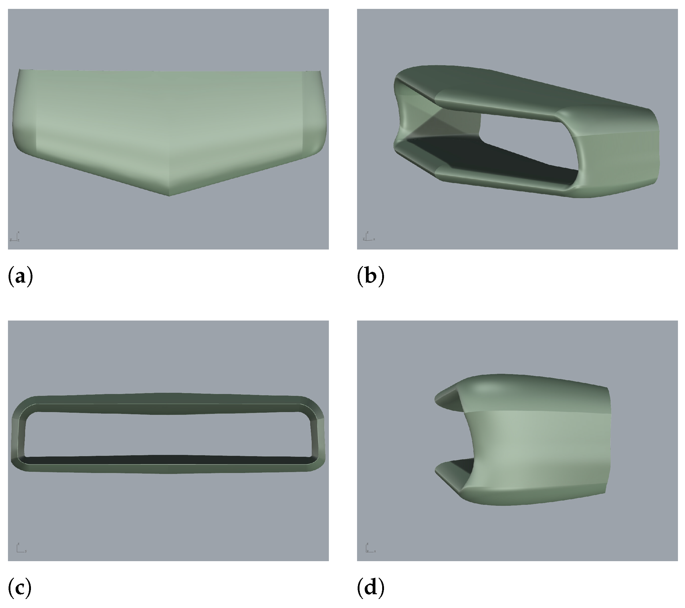
Figure 1a–d, shows the final CAD configuration of the platform, obtained using Rhinoceros software.
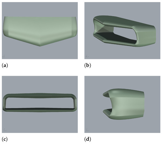
Figure 1.
Different views of the closed-wing platform: (a) top view; (b) front view; (c) rear view; (d) lateral view.
Once the initial design phase was completed, it was necessary to conduct fluid dynamics and stability analyses to assess the quality of the defined configuration and improve the design where needed.
3.1. Aerodynamic Analysis
The initial analyses, which marked the beginning of the design process, used AVL software (https://www.avl.com/en/software). During this phase, a preliminary CAD model of the platform was created and the desired airfoil profile was selected. For design reasons related to inflation and the challenge of maintaining convex curvatures during and after the inflation phase, a symmetric airfoil profile, i.e., NACA0018, was chosen. The NACA 0018 airfoil has a higher thickness compared to thinner profiles (such as 12% or 14%), providing the increased internal volume necessary for integrating stiffness structures and helium. These elements were critical for maintaining the wing’s integrity under various loads. It was also essential to provide sufficient volume to accommodate the large amount of helium required for buoyancy.
The aerodynamic parameters, specifically the lift coefficient and drag coefficient as functions of the angle of attack, were recalculated using OpenFoam software (https://www.openfoam.com/governance/overview), employing a stationary, incompressible RANS analysis with k- and a turbulence model. This process provided a more accurate estimate of these parameters, particularly in determining the value of the zero drag coefficient. This updated information was integrated back into the design process to further enhance the results of the conceptual design.
The first step of the aerodynamic analysis involved generating an unstructured mesh of the platform and the surrounding area of interest. The flow conditions were simulated at an altitude of 20 km with an airspeed of 16 m/s. The simulations were conducted at a Reynolds number of 750.000. The attitude varied with an angle of attack ranging from to 22° and slip angles of 0°, , , and . An unstructured grid was generated using Ansys Fluent, combining prismatic elements in the boundary layer and tetrahedrons in the outer regions. It consisted of elements and nodes. To ensure < 1, the boundary layer was modeled with an initial layer height of 0.0001, a maximum of 31 layers, and a growth rate of 1.25.
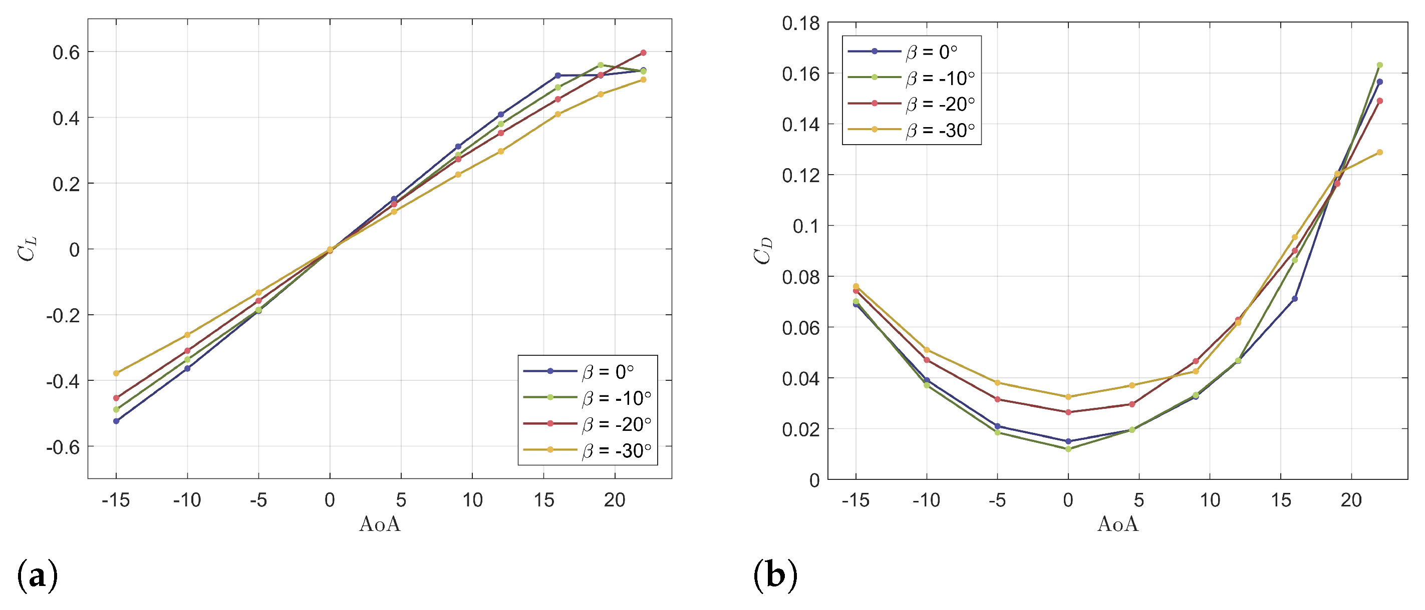
The curves relative to the lift and drag coefficients, varying with the angle of attack, were compared for different slip angles, and are shown in Figure 2a,b. It is possible to observe that stalling occurs within an angle range between 18° and 20° at β = 0°.
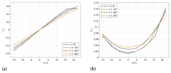
Figure 2.
Closed − wing lift–drag curve: (a) lift coefficient vs. angle of attack for different slide angles and ; (b) drag coefficient vs. angle of attack for different slide angles and .
Starting from the force coefficient curves, analytical expressions can be derived as functions of the angle of attack () and the side-slip angle (), both measured in degrees. These expressions, shown in Equations (5) and (6) for the lift coefficient, and in Equations (7)–(10) for the drag coefficient, approximate the behavior of the curves. They are useful for developing an aerodynamic database of the simulation model.
3.2. Longitudinal Stability Analysis
The stability analysis focused on the static stability with respect to the three rotations: pitch (y-axis), yaw (z-axis), roll (x-axis).
Longitudinal stability is achieved by correctly positioning the force application points: the center of volume (), the aerodynamic center (), and the center of gravity (). For stability, the aerodynamic center must be located behind the center of gravity (), which ensures a positive restoring moment. Ideally, the center of volume is positioned in front of the center of gravity (). When is behind , any disturbance that increases the angle of attack results in a nose-down moment, helping the aircraft return to its original state.
By carefully adjusting the masses of the subsystem to maintain the relative positions of the force application points, particularly the center of gravity, longitudinal stability is achieved, as illustrated in Figure 3a. The relative positions of , , and are listed in Table 4. These adjustments lead to the conditions outlined in Equations (11) and (12).
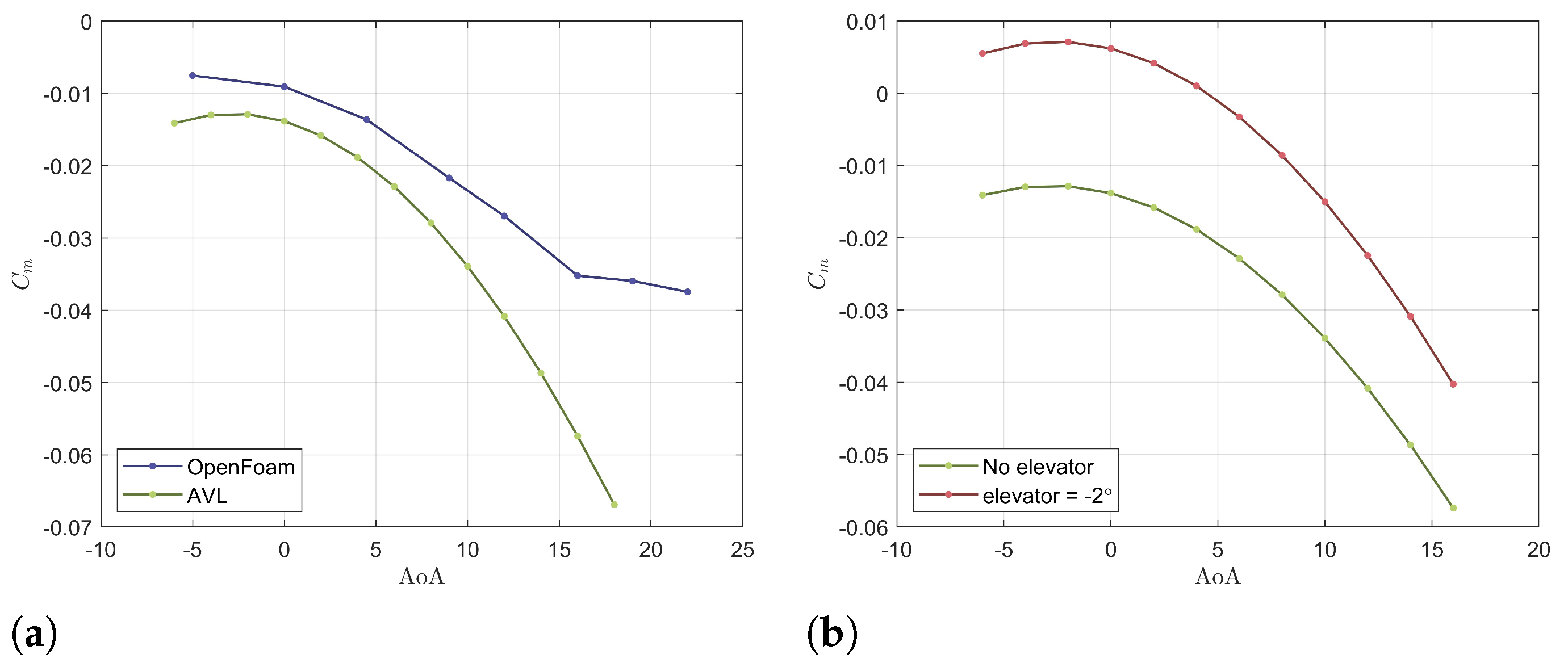
In the configuration under consideration, not all conditions are satisfied. Specifically, the trim condition described by Equation (12) is not satisfied. This problem arises from the moment generated by buoyancy (), which shifts the moment coefficient curve downward, as shown in Figure 3a. This figure was obtained through a RANS simulation in OpenFoam and using the Vortex Lattice method in AVL software. Although the moment coefficient curve has a negative slope, it does not intersect the x-axis. To solve this problem, a control surface known as an elevator is used, a common solution in “all-wing” configurations without a tailplane.
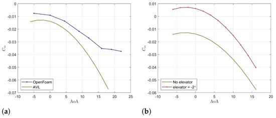
Figure 3.
(a) Comparison of pitching moment curves obtained using OpenFoam and AVL software; (b) comparison of pitching moment curves with different elevator deflections using AVL.
Table 4.
, , and positions along longitudinal and vertical axes.
Figure 3b shows that the equilibrium condition for the designed angle of attack is achieved with an elevator deflection of about 2°. For simplicity, calculations involving the control surface were performed using AVL.
3.3. Lateral-Directional Stability Analysis
Regarding the lateral-directional analysis, the aerodynamic derivatives (rolling moment with respect to the side-slip angle, ) and (yawing moment with respect to the side-slip angle, ) were obtained. More specifically, the desired conditions are for lateral stability and for directional stability.
The stability analysis highlights the need to modify the geometry to achieve lateral equilibrium. As a result, the upper wing was modified, transitioning from an elliptical distribution to a flat wing geometry while maintaining the wingspan. This decision was driven by the fact that, in the initial configuration, the inclination of the upper wing forms a negative dihedral angle, which destabilizes the platform’s lateral stability.
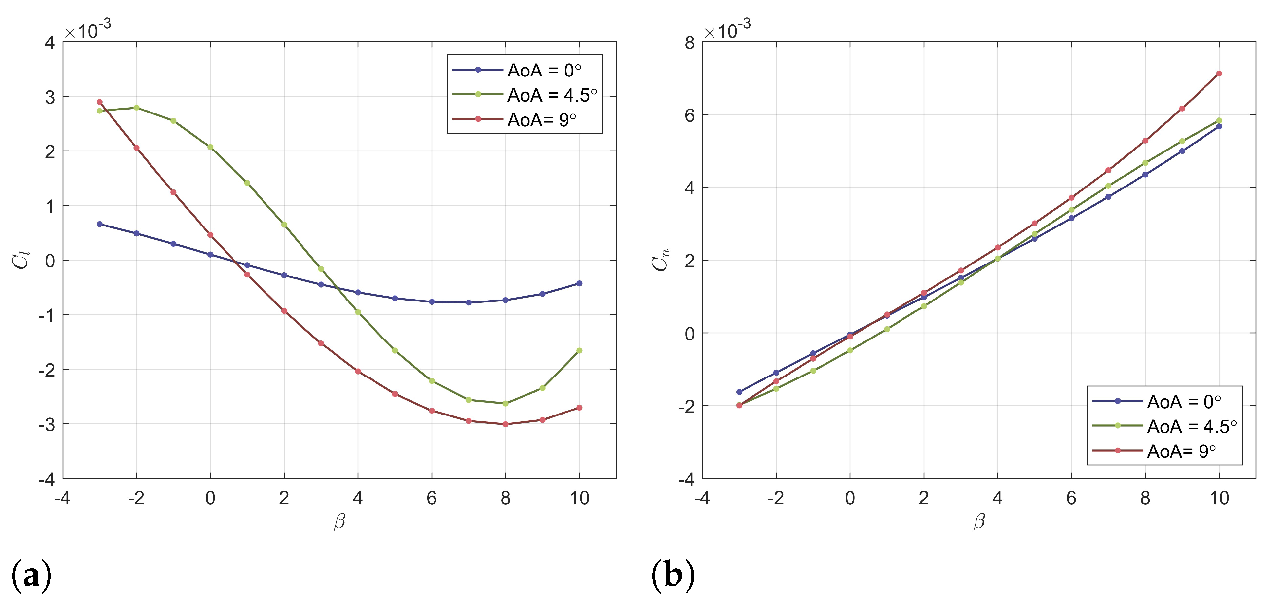
Condition was achieved by incorporating a swept angle and adjusting the wing design to produce a dihedral angle that is not excessively negative for the upper wing, thus improving the lateral stability of the aircraft. Through these modifications, both lateral and directional stabilization of the platform were achieved, as shown in Figure 4a,b. These curves were obtained through a RANS simulation performed in OpenFoam for three different angles of attack: 0°, 4.5°, and 9°.
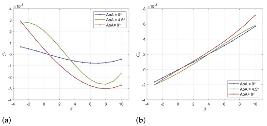
Figure 4.
Lateral− directional stability curves produced in OpenFoam: (a) roll moment coefficient with respect to for three different AoAs; (b) yaw moment coefficient with respect to for three different AoAs.
4. Conclusions
This paper presents a conceptual design of a hybrid stratospheric platform, focusing on its geometric configuration, aerodynamic properties, and static stability. The study’s results show that stability is closely related to the relative positions of the aerodynamic center, center of gravity, and center of volume, as well as the platform’s geometry.
Regarding longitudinal stability, the pitching moment curve shows that the presence of a sweep angle and a large root chord results in a negative derivative of with respect to the angle of attack (AoA) due to the relative position of , , and . However, it is observed that the trim condition is not achieved at the designed angle of attack due to the influence of buoyancy, despite the condition being met. Through various analyses, it is found that the trim condition at the desired angle of attack can be achieved by incorporating control surfaces, specifically elevators, with the hinge placed at 75% of the chord. As a first approximation, these are installed on the lower and upper wing, requiring a deflection of 2°.
For lateral and directional stability, the initial design analysis reveals that the elliptical-shaped upper wing fails to achieve lateral stability due to the destabilizing effect of the negative dihedral angle. To address this, the configuration is modified by changing the upper wing from an elliptical to a linear shape and incorporating a sweep angle. These adjustments ensure that the specific stability conditions, and , are met. A junction with a lateral wing component is also added to avoid sharp right angles while maintaining the wingspan obtained from the earlier analysis. In conclusion, the results of this study confirm that, through these modifications, the new configuration is stable along all three axes.
Author Contributions
Conceptualization, C.G. and E.R.; methodology, C.G. and E.R.; software, C.G. and E.R.; validation, C.G. and E.R.; formal analysis, C.G. and E.R.; data curation, C.G. and E.R.; writing—original draft preparation, C.G. and E.R.; writing—review and editing, V.R.B., G.P. and D.C.; supervision, V.R.B.; project administration, G.P. All authors have read and agreed to the published version of the manuscript.
Funding
This work was funded by the Italian Space Agency (ASI), in the framework of the project STOPP (Grant: N. 2021-42-HH.0, CUP: F45F21001650005).
Institutional Review Board Statement
Not applicable.
Informed Consent Statement
Not applicable.
Data Availability Statement
Data are contained within the article.
Conflicts of Interest
The authors declare no conflicts of interest.
References
- Baraniello, V.R.; Persechino, G.; Borsa, R. Tools for the Conceptual Design of a Stratospheric Hybrid Platform; SAE International, Thecnical Paper; SAE: Warrendale, PA, USA, 2020; No. 2020-01-0025. [Google Scholar]
- Baraniello, V.R.; Persechino, G.; Angelino, C.V.; Tufano, F. The application of high altitude pseudo-satellites for a rapid disaster response. In Proceedings of the IEEE International Geoscience and Remote Sensing Symposium IGARSS, Brussels, Belgium, 11–16 July 2021; pp. 8400–8403. [Google Scholar]
- Prandtl, L. Induced Drag of Multiplanes; NACA TN-182. 1924. Available online: https://ntrs.nasa.gov/citations/19930080964 (accessed on 18 July 2021).
- Schiktanz, D.; Scholz, D. Box wing fundamentals—An aircraft design perspective. In Proceedings of the DGLR: Deutscher Luft-und Raumfahrtkongress, Bremen, Germany, 27–29 September 2011. [Google Scholar]
- Rizzo, E. Optimization Methods Applied to the Preliminary Design of Innovative Non-Conventional Aircraft Configurations; ETS: Pisa, Italy, 2007. [Google Scholar]
- Anderson, J.D.; Bowden, M.L. Introduction to Flight, 8th ed.; McGraw-Hill Education: New York, NY, USA, 2005. [Google Scholar]
- Bergman, D. Modelling & Implementation of Aerodynamic Zero-Lift Drag into ADAPDT. Bachelor’s Thesis, Aeronautica Engeneering, Malardalen University, Västerås, Sweden, 3 November 2009. [Google Scholar]
- Köthe, A. Flight Mechanics and Flight Control for a Multbody Aircraf; Technische Universitaet Berlin: Berlin, Germany, 2019. [Google Scholar]
- Noth, A. Design of Solar Powered Airplanes for Continuous Flight. Doctoral Dissertation, ETH Zurich, Zürich, Switzerland, 2008. [Google Scholar]
- Colozza, A.J.; Dolce, J. Initial Feasibility Assessment of a High-Altitude Long Endurance Airship; NASA Technical Reports Server (NTRS): Cleveland, OH, USA, 2003.
- Colozza, A. Effect of Power System Technology and Mission Requirements on High Altitude Long Endurance Aircraft; NASA Technical Reports Server (NTRS): Brook Park, OH, USA, 1994; pp. 4–8.
- Carichner, G.E.; Nicolai, L.M. Fundamentals of Aircraft and Airship Design: Volume 2—Airship Design and Case Studies; AIAA Education: Reston, VA, USA, 2013. [Google Scholar]
Disclaimer/Publisher’s Note: The statements, opinions and data contained in all publications are solely those of the individual author(s) and contributor(s) and not of MDPI and/or the editor(s). MDPI and/or the editor(s) disclaim responsibility for any injury to people or property resulting from any ideas, methods, instructions or products referred to in the content. |
© 2025 by the authors. Licensee MDPI, Basel, Switzerland. This article is an open access article distributed under the terms and conditions of the Creative Commons Attribution (CC BY) license (https://creativecommons.org/licenses/by/4.0/).