Abstract
This paper presents an innovative active monitoring strategy to manage asymmetry in aircraft flaps. Complex mechanical systems like high-lift devices may undergo a wide range of faults, such as a broken transmission torsion bar or wear and tear on control surface actuators just to name a few. These faults can alter the surface symmetry between the two sides of the wing, potentially leading to dangerous conditions. The proposed relative dynamic position control technique provides a more effective monitoring method to detect and identify flap asymmetry. Once the faulty side has been identified, the system activates the wingtip brakes to halt the uncontrolled flap. The remaining functional flap is then moved to match the braking point of the failed flap, reducing the asymmetry. This approach effectively manages the unwanted roll moment caused by flap asymmetry, thereby partially restoring the aircraft’s maneuverability post-failure. The proposed monitoring technique has been subjected to extensive testing under various operational and failure conditions with the use of a mathematical model, with both new and worn actuators, and considering a wide range of possible failure scenarios.
1. Introduction
The Flight Control System (FCS) in commercial and military aircrafts is responsible for the movement of the aerodynamic surfaces used to control the aircraft attitude and direction. On conventional aircrafts, a common distinction is made between primary flight controls and secondary flight controls. On the one hand, primary flight controls are essential for the aircraft operation in flight and usually include ailerons, elevators (or, in some configurations, a stabilator), and the rudder. On the other hand, secondary flight controls are designed to improve the flight and performance characteristics of the aircraft or to alleviate excessive loading on the control line. These include high-lift devices such as slats and flaps, as well as flight spoilers and trim systems [1].
In particular, even if not essential for maneuvring the aircraft, wing trailing edges (i.e., flaps), along with slats (their counterpart on the leading edges) are employed to enable a safer aircraft operation in low-speed conditions, by incrementing the wing maximum lift coefficient. In fact, during take off and landing, the interaction of low airspeed and high angle of attack may lead to an aerodynamic stall condition and an increase in lift using these additional surfaces is a consolidated practice. As a result, lower stalling speed is achieved and the lift-to-drag ratio is enhanced, facilitating shorter take offs and slower approaches, as well as a more controllable aircraft behavior. In this study, for the sake of simplicity, only flaps are taken into consideration.
Since a flap failure would indeed impair aircraft performance but without compromising flight safety or aircraft controllability, flaps are usually not classified as safety-critical elements. However, one of the most stringent safety design criteria pertains to the actuation symmetry of each movable surface. In fact, if a flap asymmetry takes place, the overall aircraft controllability is at stake, since an aerodynamic asymmetry would lead to a lift unbalance and the resulting rolling moment would affect the aircraft leading to potential catastrophic failure conditions, especially near the ground level [2]. The quantifiable symmetry alteration between left and right flaps is usually very limited in nominal conditions, since extremely stringent backlash specifications are imposed on the mechanical transmission line. The mechanical transmission deflection is negligible even in asymmetry conditions (backlash less than 0.05%, deflection less than 0.5% of the full flap travel [3]); however, the failure of the mechanical transmission, the jamming of the surface or of the related actuator are possible events that must be taken into account [4,5]. As a consequence, additional safety protocols and strategies must be implemented to ensure compliance with the required safety standards: the so-called asymmetry protection strategies. In this sense, asymmetry and overloading tolerant architectures with force limiters, torque limiters or slipping clutch can be envisioned by design. On the other hand, flap asymmetry monitoring techniques, with the aim of detecting the possible behaviors deviation towards non nominal conditions, can provide a useful way to alert the pilots in advance, enabling a prompt intervention and action to mitigate the issue.
This paper is the natural extension of the authors’ previous work [6,7]; in this present paper, additional strategies are reported providing a step forward in relation to the other study. The remainder of the paper is organized as follows: a brief introduction of the common flap configurations is reported along with a description of the mathematical model implemented to simulate trends. Then, an overview of the main monitoring techniques is presented. Finally, the novel technique developed by the authors is delineated, accompanied by relevant simulations and results.
2. Flap Systems and Generic Configuration
The flap configuration has changed much in the years shifting from a purely mechanic configuration to a hydraulically powered one. Among the most common architectures, the most famous ones are plain flap, fowler flap, slotted flap, double slotted flap, etc. While this document does not encompass a thorough analysis of the entire system, further information can be found in sources such as [8,9]. The systems consist of hydraulic or electric motors driving a mechanical transmission ending with either linear or rotary mechanical actuators which provide the movement of the aerodynamic surfaces along metal tracks placed in the wing. Below is a summary of the components and their operational principles for clarity.
- Power Drive Unit (PDU). The PDU is the power unit that provides power to the surface often from the hydraulic circuit.
- Power Control Unit (PCU), which controls the actuation process.
- Drive shafts and torsion bars. They are utilized to transmit motion from the motor output shaft to the user interface, specifically the flap surfaces, via the actuators [10].
- Actuators. They are positioned between the torsion bars and the flight surfaces. Typically, they consist of ball screws or a screw-and-nut mechanism.
- Servo valves, solenoid and shut-off valves.
- Mechanical links and components.
Reversible actuators are the predominant type of actuators used in high-lift devices, primarily because of their cost-effectiveness and the ease with which they facilitate pre-flight checks. Moreover, a widely adopted solution involves the installation of wing-tip brakes on the transmission line, positioned near the electrical flap position transducer. These wing-tip brakes are subsequently managed using asymmetry monitoring techniques.
3. Monitoring Strategies
It has to be noted that the vast majority of solutions are not published in scientific papers since they remain in the industry, and a literature review on the topic reveals a scattered panorama. Nevertheless, the known strategies are usually divided based on the type of signal monitored or on the overall type of response. As such, they can be divided into active or passive depending on the type of response:
- Passive monitoring techniques are designed to detect asymmetry in flap positions without specifying the wing side of the failure. Consequently, the corrective maneuver for addressing asymmetry involves applying brakes to both control surfaces once the anomaly is identified.
- Active techniques are more advanced and complex as they not only detect the anomaly but also identify the faulty side and try to establish a stable aircraft condition. In fact, two actions are performed: first of all, as soon as the failure arises, the faulty surface is braked. Secondly, the still-operational flap is moved to reach the position of the non operational side. In this way, the asymmetry is reduced even more and the effect on the aircraft’s stability and maneuverability is minimized.
In general, position asymmetry monitoring techniques exploit a similar methodology for both identifying asymmetry failure conditions and applying brakes to the affected surface. The process begins with the detection of the asymmetry anomaly by comparing the signals received from each side actuator. If this comparison reveals an exceedance of a predefined asymmetry threshold for a specified duration (determined with a counter), the system will indicate a position asymmetry failure. Upon detection of the asymmetry failure, the hydraulic unit will be depressurized, resulting in the activation of the wingtip brakes to halt the impaired surface. These models may take into account either the position of the control surfaces alone or both the position and speed of the flaps. Specifically, incorporating both flap position and speed into the asymmetry monitoring models results in a more prompt declaration of position asymmetry failures in scenarios where the affected surface experiences elevated speeds.
4. Proposed Strategy
The strategy here presented can be classified as an active, enhanced relative position-driven, step-input control technique, as per [11]. It involves partial asymmetry detection and general asymmetry detection. The partial logic identifies the faulty wing side while the general one manages the eventual multiple failure situation (i.e., when the failure is on both sides), bringing benefits in terms of system robustness and stability. The active logic presented in this work is a further enhancement of the logic shown in [6,7], thanks to the addition of a position anticipation term within the monitoring technique logic. Not only does this improvement enhance the detection of surface failures through the dynamic position term but also engages the braking system of the affected surface in the event of a failure. In other words, the system equation has an extra position term called Anticipated Electrical Position (AEP). The AEP is calculated using the first derivative of the differential position. The AEP term in the dynamic position model proves to be particularly valuable in scenarios characterized by a high airspeed, where the failure surface experiences significant retraction speeds. In such instances, it is critical to identify the asymmetry failure declaration at the earliest opportunity, prior to the inoperative flap reaching an excessively retracted braking position following failure. Therefore, it is imperative to incorporate the failure surface speed into the active model algorithm to preemptively trigger the asymmetry failure declaration, thereby activating the braking system before the surface accelerates to potentially harmful levels. The partial asymmetry detection logic is reported in Equation (1).
where represents the motor position, and are the motor and the gear ratio of the actuator, is the surface position, and represents the left and right flap. The term is needed to make the units of measure coherent and in particular can be seen as a characteristic time of the system. Finally, is a modulation parameter that is employed to decide if the AEP term is needed. In particular, the AEP term is needed only in high aerodynamic torque conditions, while it may cause instability in low aerodynamic torque situations due to the derivative of the position. The aerodynamic constant torque is referred to as AT. The AT is generated by aerodynamic forces acting upon the flap and has indeed a significant influence on the flap’s behavior. As a result, the term , called control parameter, is treated as a boolean value which is equal to zero if and one otherwise. In further developments, a more precise and modulated law for this parameter can be envisioned. is set empirically to 4000 N/m. The algorithm is designed to identify potential asymmetry failure conditions by comparing the relative dynamic position reference of either the left or right surface against a predetermined angular position threshold, empirically established at rad. When this position threshold is surpassed, an asymmetry failure is confirmed. When this condition is satisfied, either for the left or right surface, the partial asymmetry counter, denoted as , increments. Once this counter reaches the threshold value , the partial asymmetry indicator is triggered. This indicator is a boolean variable that is set to 1 in the event of a failure or 0 when there is no failure. Additionally, further general logic is incorporated.
The general logic is reported in Equation (2).
It has to be noted that no control parameter is used in the general failure algorithm, which is consistently set to . In contrast, partial asymmetry detection requires a control parameter to stabilize the position dynamics following the failure occurrence, based on the applied aerodynamic torque. However, in the case of a general failure, a control parameter is unnecessary. The braking system effectively halts any surface motion upon detection of the failure, mitigating the risk of dynamic instability. Additionally, the position anticipation term should always be activated to ensure the immediate braking of both flaps, thereby preventing severe asymmetry consequences during the remainder of the flight.
5. Employed Physics-Based Model
In order to test the aforementioned strategy, a parametric physics-based model of the system has been employed. The model is the same that has been used in [6] and it manages to simulate both flaps mechanical and dynamic behavior as well as the roll dynamics of the aircraft in conjunction of the autopilot system. As a matter of fact, the lateral–directional modeling describes the vehicle’s roll dynamics in the event of the asymmetry of flap positions and the autopilot manages the rolling moment of the aircraft, trying to keep a stable and leveled flight attitude. A detailed description of the model goes well beyond the scope of this article; the interested reader should consider reading [11] for further explanations and details. Nonetheless, for reasons of clarity, a block diagram with a short description of the working principles is reported hereafter. Figure 1 shows the main block diagram of the model.
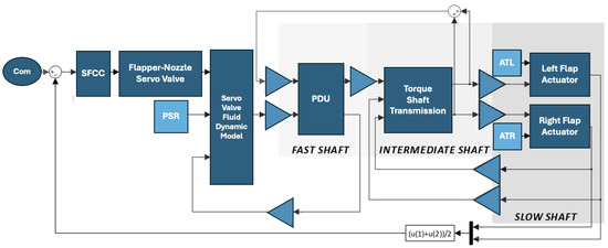
Figure 1.
Block diagram of the flap system model. The motion is transferred from the fast shaft of the PDU, to the intermediate shaft of the transmission and finally to the slow shaft of the mobile surface itself.
The position commands are generated and then handled by the surface slats–flaps computer controller, which employs a simple PID controller to handle commands and provides, thanks to monitory and asymmetry control algorithms, the command signals to the hydraulic servo valve. The modeled servo valve is a flapper—nozzle-type servo valve as commonly employed in aerospace applications for their ruggedness and reliability. In this case, it is modeled thanks to a third-order electromechanical model which outputs the spool position. Then, a servo valve fluid dynamic model is used to correlate spool displacement to the differential pressure and finally the flow rate, which is then passed to the PDU. This element is modeled as a second-order degree system that transforms hydraulic power to mechanical power evaluating, inertia, elastic torque of each transmission line shaft, viscous damping and internal friction phenomena. The motion transmission model evaluates the backlash and stiffness of the torque shaft, universal joint and gear boxes, detailing specific parameters for the left and right lines. The left and right actuators are responsible for providing linear motion to the mobile surfaces and receive as inputs ATL and ATR, which are the values of aerodynamic load acting as both left and right flap surfaces.
The model simulates the behavior of the system considering various factors including variable pressure supply, friction [7], backlash, stiffness of the transmission shafts, noise on the signal lines, and mechanical transmission failures. A comprehensive explanation of each individual block and equation, as well as a description of the hydraulic and mechanical component modeling, is available in the references [11].
6. Results
A series of evaluations were conducted to analyze the system’s performance and identify the primary benefits and drawbacks associated with the proposed active monitoring technique. To achieve this objective, a simulation and testing initiative was executed, which involved the assessment of the following variables for each model:
- Flap extension or retraction;
- Extraction/retraction magnitude;
- Failure side: Failure on the right or left half of the wing;
- AT (to simulate different flight conditions);
- Worn/not-worn actuator (simulated by increasing friction).
The time at which the failure is injected in the system () for all tests is set at 0.4 seconds. A comprehensive range of simulations has been conducted under various conditions by varying the aforementioned parameters. To maintain conciseness, only a selection of these results, specifically those involving failures on the left flap, is documented within this paper. It is important to note that the observed behavior is analogous to the right semi-wing as well. A more detailed analysis, including additional results, is available in reference [11].
The simulations were carried out with left faulty flap in the conditions reported in Table 1. Some scenarios (A, B, E, F) represent simulations of maneuvers conducted under conditions of low aerodynamic load. Conversely, scenarios C, D, G, H are classified as maneuvers performed under high aerodynamic load, which are of particular significance due to the enhanced visibility of the phenomena involved. A sub-set of simulations has also been executed under worn-out conditions (scenarios E, F, G, H), resulting in a total of eight distinct cases being documented.

Table 1.
Experiments parameters. Direction can be extraction (E) or retraction (R); start and end positions are reported in radiants.
7. Discussion
In Figure 2 and Figure 3, DThM denotes the motor speed, while ThSL and ThSR represent the angular positions of the left and right flaps, respectively. ThA indicates the aileron deflection angle, ThM refers to the motor position, and RoA illustrates the behavior of the aircraft’s roll angle. All angles are expressed in degrees on the graph’s right y-axes along with the speeds [deg/s], as reported in Table 2. The variables IAsL, IAsR, and IAs serve as anomaly indicators for the left, right, and general conditions, respectively, each of which can assume a boolean value of 0 or 1, reported on the left y-axes.

Figure 2.
Simulation results of nominal flap extraction and retraction under various operational scenarios; no wear on components.
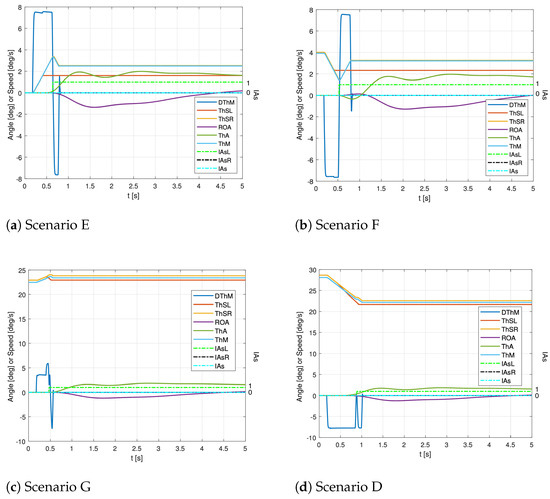
Figure 3.
Simulation results of nominal flap extraction and retraction under various operational scenarios, wear on components.
Table 2.
Study parameters and measurement units.
At 0.4 s, a simulated fault in injected into the system. ThSL no longer aligns with ThA, indicating a breakdown in transmission. Following the fault, the motor experiences a significantly increased speed as it attempts to restore the position ( spike). Once the counter reaches the predetermined threshold, the anomaly indicator transitions to one (as shown by the dotted green line). The side of the failure is accurately detected, as only the anomaly indicator is raised to one. The provided signal enables the operative surface (the right one) to effectively minimize roll torque through a slight retraction, as indicated by the trend. However, this adjustment impacts the aircraft’s dynamics, resulting in a roll moment; this is evident from the changes in the roll angle () due to the limited aileron movement (), handled by the autopilot. The operative flap does not achieve the same degree of retraction as the faulty flap due to the electric transducer’s offset and errors.
In scenarios of high AT, the flap system section experiences a sudden retraction due to aerodynamic loads that push the surface backward. The monitoring system subsequently detects the failure, at which point the wingtip brake is engaged to bring the system to a complete stop. After that, the motor swiftly adjusts the operative surface to a position that closely resembles the faulty setting in order to mitigate the effects of asymmetry.
It should be reiterated that the anticipation term of the dynamic position is added only in the case of high AT, the positive effect of this term is hence visible only in scenarios C, D, G, and H, while in the other scenarios, the results are the same as presented in [6]. The braking time has been significantly reduced, which consequently minimizes both the RoA overshoot and the time-to-peak. As a result, this enhancement contributes positively to the lateral–directional stability of the aircraft.
In Figure 3, the same extraction and retraction patterns are reported in the friction case. Transmission efficiency is lowered and the overall system reliability is significantly reduced. The results of the new strategy under high AT on wear-out conditions present great improvements with respect to the model without the AEP, especially in case of failure during retraction. When compared to the findings presented in [6], the dynamic position demonstrates a proactive response to potential failures during high AT conditions and a reduced detection time. Consequently, a higher retracting speed results in a more rapid increase in the dynamic position, thereby facilitating earlier identification of the partial asymmetry failure condition.
8. Conclusions
A further development of an active asymmetry monitoring strategy for high-lift devices has been presented. Despite not being primary flight controls, flaps are especially critical components in relation to asymmetry conditions. The addition of a dynamic term into the monitoring strategy with respect to the previous model iteration presented by the authors in a previous paper helps the reactivity of the alert system, especially in the presence of high aerodynamic load. The methodology has been tested under nominal conditions as well as in scenarios with increased friction, demonstrating satisfactory results, as the impact of the failure on the aircraft dynamics remains contained.
Author Contributions
Conceptualization, M.D.L.D.V.; Methodology, M.D.L.D.V. and J.M.C.R.; Software, M.D.L.D.V. and J.M.C.R.; Validation, J.M.C.R.; Formal Analysis, J.M.C.R.; Investigation, J.M.C.R.; Resources, M.D.L.D.V.; Data Curation, J.M.C.R.; Writing—Original Draft Preparation, L.B. and J.M.C.R.; Writing—Review & Editing, L.B.; Visualization, L.B. and J.M.C.R.; Supervision, M.D.L.D.V.; Project Administration, M.D.L.D.V.; Funding Acquisition, M.D.L.D.V. All authors have read and agreed to the published version of the manuscript.
Funding
This research received no external funding.
Institutional Review Board Statement
Not applicable.
Informed Consent Statement
Not applicable.
Data Availability Statement
Not Applicable.
Conflicts of Interest
The authors declare no conflicts of interest.
References
- Etkin, B.; Reid, L.D. Dynamics of Flight; Wiley: New York, NY, USA, 1959; Volume 2. [Google Scholar]
- Ize, C.; Arena, A. Effects of asymmetric leading edge flap deflection on delta wings in roll. In Proceedings of the 22nd Atmospheric Flight Mechanics Conference, New Orleans, LA, USA, 11–13 August 1997. [Google Scholar] [CrossRef]
- Borello, L.; Villero, G.; Dalla Vedova, M.D.L. Flap failure and aircraft controllability: Developments in asymmetry monitoring techniques. J. Mech. Sci. Technol. 2014, 28, 4593–4603. [Google Scholar] [CrossRef]
- Zhou, C.; Chang, Q.; Zhao, H.; Ji, M.; Shi, Z. Fault Tree Analysis with Interval Uncertainty: A Case Study of the Aircraft Flap Mechanism. IEEE Trans. Reliab. 2021, 70, 944–956. [Google Scholar] [CrossRef]
- Xiang, F.; Cui, W.; Zhong, Y. The failure mode analysis of motion mechanism for airbus A320 flap. In Proceedings of the 2011 International Conference on Quality, Reliability, Risk, Maintenance, and Safety Engineering, Xi’an, China, 17–19 June 2011; IEEE: Piscataway, NJ, USA, 2011; Volume 6, pp. 64–66. [Google Scholar] [CrossRef]
- Baldo, L.; Ruiz, J.C.; Dalla Vedova, M.D.L. Novel active control technique of aircraft flaps asymmetry. J. Phys. Conf. Ser. 2023, 2526, 012004. [Google Scholar] [CrossRef]
- Belmonte, D.; Dalla Vedova, M.D.L.; Quattrocchi, G. A new active asymmetry monitoring and control technique applied to critical aircraft flap control system failures. MATEC Web Conf. 2019, 304, 04011. [Google Scholar] [CrossRef]
- van Dam, C.P. The aerodynamic design of multi-element high-lift systems for transport airplanes. Prog. Aerosp. Sci. 2002, 38, 101–144. [Google Scholar] [CrossRef]
- Maré, J.C. Aerospace Actuators 2: Signal-by-Wire and Power-by-Wire, Volume 2; John Wiley & Sons: Hoboken, NJ, USA, 2017. [Google Scholar]
- Borello, L.; Villero, G. Mechanical failures of flap control systems: Proposal of advanced monitoring techniques. Int. J. Mech. Control 2004, 5, 9–28. [Google Scholar]
- Cedujo Ruiz, J.M. Design and Development of Innovative Asymmetry Active Monitoring Techniques for High-Lift Actuation Systems; Technical Report; Politecnico di Torino: Torino, Italy, 2021. [Google Scholar]
Disclaimer/Publisher’s Note: The statements, opinions and data contained in all publications are solely those of the individual author(s) and contributor(s) and not of MDPI and/or the editor(s). MDPI and/or the editor(s) disclaim responsibility for any injury to people or property resulting from any ideas, methods, instructions or products referred to in the content. |
© 2025 by the authors. Licensee MDPI, Basel, Switzerland. This article is an open access article distributed under the terms and conditions of the Creative Commons Attribution (CC BY) license (https://creativecommons.org/licenses/by/4.0/).