
Combining Additive Manufacturing Techniques for High-Performance Stiffened Panels †


Abstract
1. Introduction
2. Experimental Section
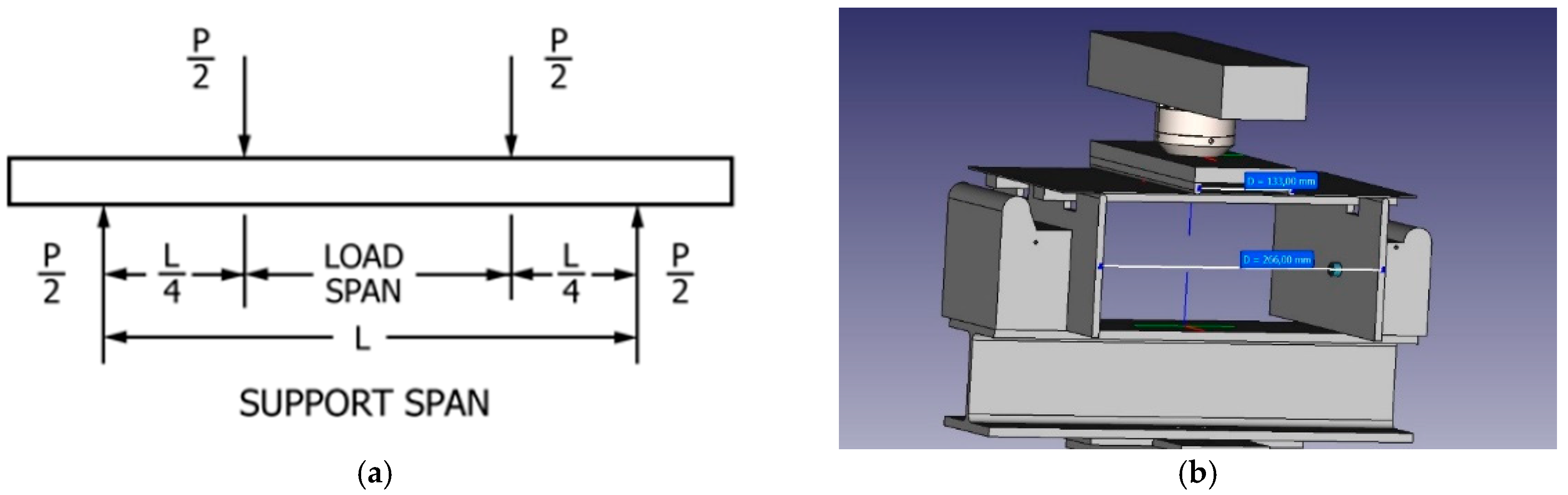
Four-Point Bending Test
- Preload at 5 N/Load up to 700 N/unloading;
- Preload at 5 N/Load up to 700 N/unloading;
- Preload at 5 N/Load up to 1000 N/unloading;
- Preload at 5 N/Load up to 1850 N, then continue up to breakage/unloading;
- Load up to total breakage.
3. Results
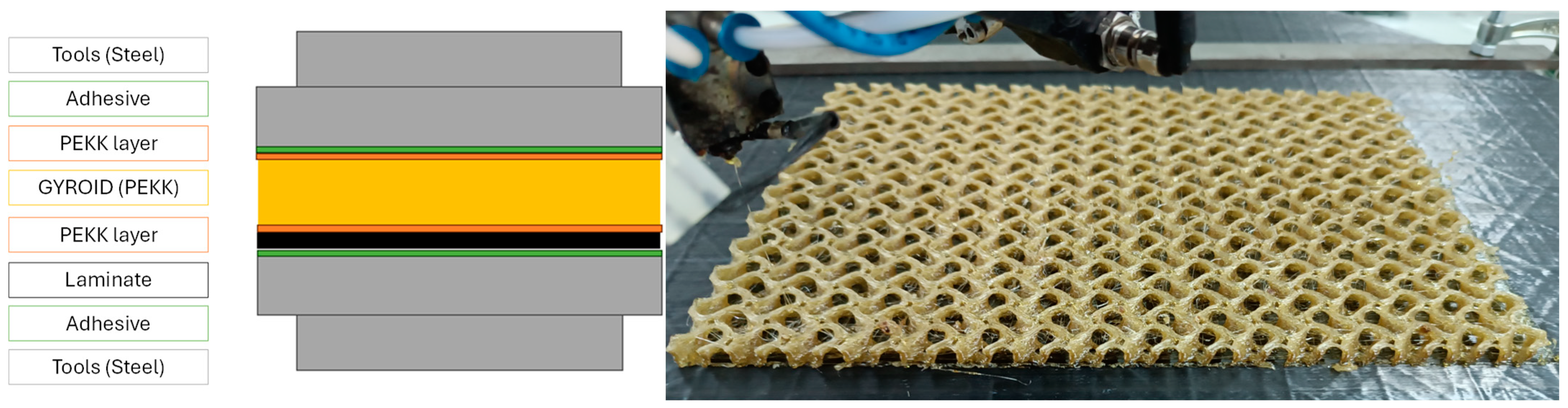
3.1. Flatwise Test
3.2. Four-Point Bending Test
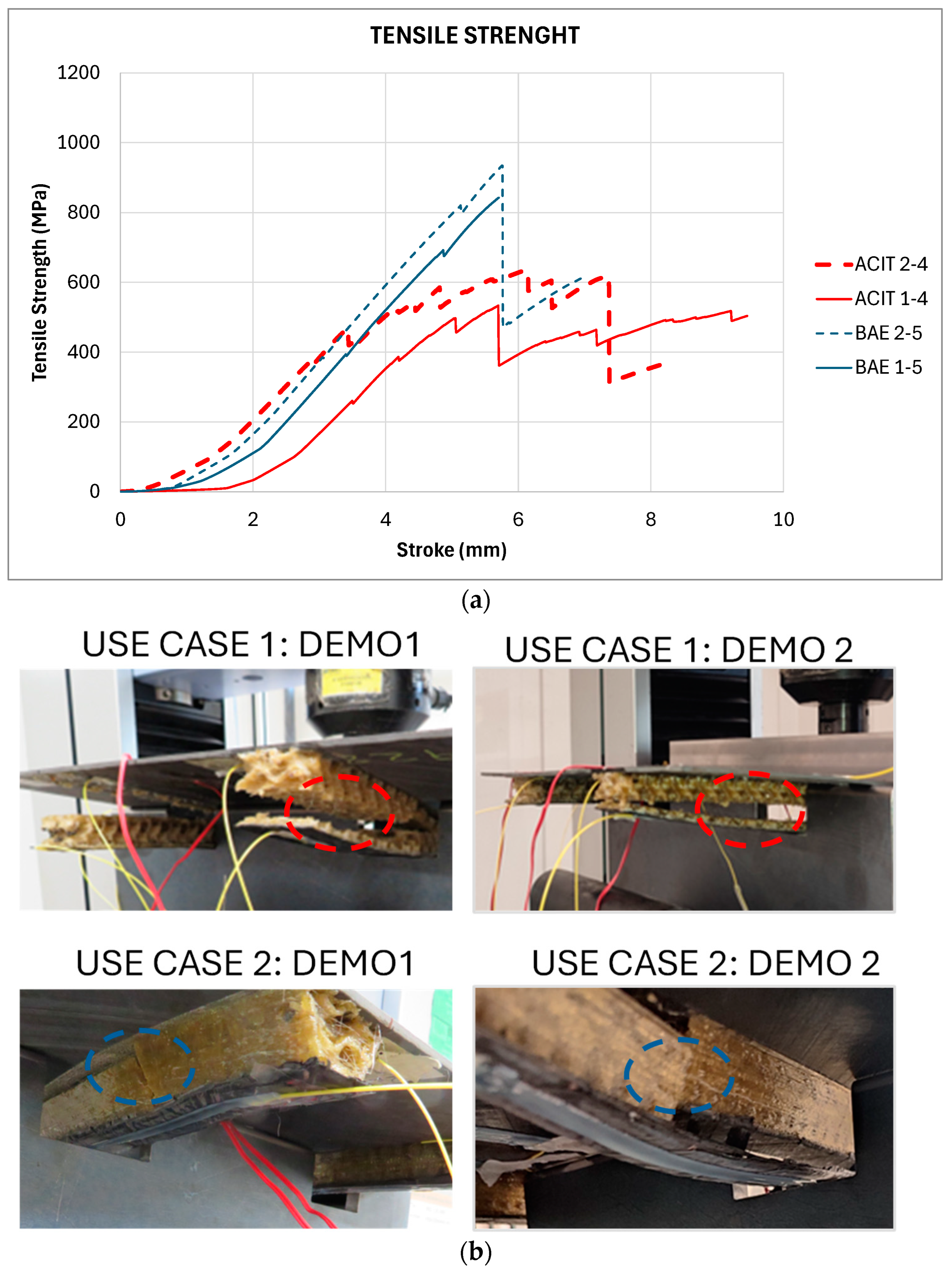
- (U1-D1): At first, some micro failures occur inside the gyroid structures until the first visible failures appear, being cracks in one of the stiffeners at 3600 N of load and 5.1 mm of stroke. The cracks within the gyroid structure continued to grow with the increasing load, achieving a maximum load of 3883 N and 5.6 mm stroke, reaching a flexural strength of 533.44 MPa.
- (U1-D2): The failure mode is similar to that obtained for U1-D1 stiffened laminate’s cohesive failure mode at different levels of the gyroid structure. A crack/delamination appeared in the center of one stiffener, between the carbon laminate and PEKK stiffener, and it was propagated along it, generating a delamination in the middle of it. While stiffener 2 did not collapse, the maximum load is similar to that obtained for U1-D1, while the stroke is a little lower. The maximum load achieved was 4621N at 6.3mm of stroke, reaching a maximum flexural strength of 635.03 MPa.
- (U2-D1): Figure 4 shows the pictures of the stiffened broken laminate at the end of the four-point bending test. In this case, the failure mode is cohesive, since it has failed between the first layer printed with laser against the laminate and the printed stiffener, although the breakage occurred between the printed structures and not at the joint between the FFF and the AFP laminate. When the deformation is sufficiently high, the stiffener fails transversaly, as can be seen in Figure 4. This may be due to the increased stiffness of the gyroid structure, achieved by covering both side walls with a polymer layer. In this case, some cracking sounds began to be heard at 2800 N; at 5000 N, the laminate cracks sound louder and stronger; and at 6200 N, the laminates finally break. The graph in Figure 4 shows that the maximum achieved load of 6133 N occurred at a stroke of 5.8mm, reaching a maximum flexural strength of 842.66 MPa.
- (U2-D2): The stiffener failed by cohesive failure, the same failure mode as that of U2-D1; it failed between the first layer printed with laser against the laminate and the printed stiffener, and the breakage occurred between the printed structures and not at the joint between the FFF and the AFP laminate. In addition, the upper reinforcement by ATL laminate was cohesively separated from the printed part in one of the stiffeners. When the deformation is sufficiently high, the stiffener breaks transversasly. In this case, failure started at 5800 N, although visually, nothing was observed in the stiffened laminate. At 6803 N, stiffener 2 breaks. At this point, the test is paused and unloaded to analyze the laminate status, and then, a final load of up to 5000N if applied when stiffener 1 breaks. As Figure 4 shows, both stiffeners broke in the central–end part of the laminate, and the stiffeners detached from the carbon laminate base in the central area. The graph in Figure 4 shows the maximum value achieved, at 6803 N, which occurred at a stroke of 5.5 mm, reaching a maximum flexural strength of 934.65 MPa.
4. Conclusions
Supplementary Materials
Author Contributions
Funding
Institutional Review Board Statement
Informed Consent Statement
Data Availability Statement
Acknowledgments
Conflicts of Interest
References
- Das, A.; Chatham, C.A.; Fallon, J.J.; Zawaski, C.E.; Gilmer, E.L.; Williams, C.B.; Bortner, M.J. Current understanding and challenges in high temperature additive manufacturing of engineering thermoplastic polymers. Addit. Manuf. 2020, 34, 101218. [Google Scholar] [CrossRef]
- Gkartzou, E.; Zafeiris, K.; Tsirogiannis, C.; Pedreira, A.; Rodríguez, A.; Romero-Rodriguez, P.; Gakis, G.P.; Kosanovic-Milickovic, T.; Kyritsis, A.; Charitidis, C.A. Induction Heating of Laminated Composite Structures with Magnetically Responsive Nanocomposite Interlayers for Debonding-on-Demand Applications. Polymers 2024, 16, 2760. [Google Scholar] [CrossRef] [PubMed]
- Zarzoso, M.; Mikhalchan, A.; Mocerino, D.; Romero-Rodriguez, P.; Losada, R.; Vilatela, J.J.; González, C. Strain sensing of structural composites by integrated piezoresistive CNT yarn sensors. Compos. Part B Eng. 2024, 286, 111752. [Google Scholar] [CrossRef]
- Najmon, J.C.; Raeisi, S.; Tovar, A. Review of additive manufacturing technologies and applications in the aerospace industry. Addit. Manuf. Aerosp. Ind. 2019, 7–31. [Google Scholar]
- García-Dominguez, A.; Claver, J.; Sebastián, M.A. Integration of Additive Manufacturing, Parametric Design, and Optimization of Parts Obtained by Fused Deposition Modeling (FDM). A Methodological Approach. Polymers 2020, 12, 1993. [Google Scholar] [CrossRef] [PubMed]
- ASTM C297-94(1999); Standard Test Method for Flatwise Tensile Strength of Sandwich Constructions. ASTM: West Conshohocken, PA, USA, 1999.
- ASTM D6272-17; Standard Test Method for Flexural Properties of Unreinforced and Reinforced Plastics and Electrical Insulating Materials by Four-Point Bending. ASTM: West Conshohocken, PA, USA, 2020.
- DOMMINIO Project|Multi-Stage Manufacturing Combining ATL and 3D Printing Processes. Available online: https://www.youtube.com/watch?v=9usi16RtsSY (accessed on 20 May 2024).


| USE CASE 1 | USE CASE 2 |
|---|---|
| cuandrangular stiffener | trapezoidal stiffener |
 | 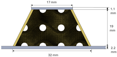 |
| ATL parameters LM-PAEK: Laser-assisted in situ consolidation: speed: 250 mm/s; compression force: 500 N, temperature: 400 °C. USE CASE 1 and 2: bottom laminates, 16 plies. USE CASE 2: top laminate, 8 plies. FFF parameters PEKK: Nozzle Tª: 370 °C; printing speed: 20 mm/s; laser preheating temperature: 350 °C. FFF parameters CCF-PEKK (Only use case 1): Nozzle Tª: 390 °C; layer height: 0.4 mm; printing speed: 10 mm/s; laser power: 7.5 W; laser preheating temperature: 350 °C. | |
| Maximum Load (N) | Flexural Strength (MPa) | Tangent Modulus of Elasticity (GPa) | |
|---|---|---|---|
| U1-D1 | 3883 | 533.44 | 1282 |
| U1-D2 | 4621 | 635.03 | 1257 |
| U1 average | 4252 ± 522 | 584 ± 72 | 1270 ± 18 |
| U2-D1 | 6133 | 842,66 | 1456 |
| U2-D2 | 6803 | 934,65 | 1476 |
| U2 average | 6468 ± 474 | 889 ± 65 | 1466 ± 14 |
Disclaimer/Publisher’s Note: The statements, opinions and data contained in all publications are solely those of the individual author(s) and contributor(s) and not of MDPI and/or the editor(s). MDPI and/or the editor(s) disclaim responsibility for any injury to people or property resulting from any ideas, methods, instructions or products referred to in the content. |
© 2025 by the authors. Licensee MDPI, Basel, Switzerland. This article is an open access article distributed under the terms and conditions of the Creative Commons Attribution (CC BY) license (https://creativecommons.org/licenses/by/4.0/).
Share and Cite
Pedreira, A.; Rodríguez, A.; González-Castro, N.; Simoes-Pereira, B.; Romero-Rodriguez, P. Combining Additive Manufacturing Techniques for High-Performance Stiffened Panels. Eng. Proc. 2025, 90, 59. https://doi.org/10.3390/engproc2025090059
Pedreira A, Rodríguez A, González-Castro N, Simoes-Pereira B, Romero-Rodriguez P. Combining Additive Manufacturing Techniques for High-Performance Stiffened Panels. Engineering Proceedings. 2025; 90(1):59. https://doi.org/10.3390/engproc2025090059
Chicago/Turabian StylePedreira, Alberto, Adrián Rodríguez, Noelia González-Castro, Beatriz Simoes-Pereira, and Pablo Romero-Rodriguez. 2025. "Combining Additive Manufacturing Techniques for High-Performance Stiffened Panels" Engineering Proceedings 90, no. 1: 59. https://doi.org/10.3390/engproc2025090059
APA StylePedreira, A., Rodríguez, A., González-Castro, N., Simoes-Pereira, B., & Romero-Rodriguez, P. (2025). Combining Additive Manufacturing Techniques for High-Performance Stiffened Panels. Engineering Proceedings, 90(1), 59. https://doi.org/10.3390/engproc2025090059