Proceeding Paper

Assessment of the Fatigue Behavior of Wings with Distributed Propulsion †

by
Lukas Kettenhofen
1,*,‡,
Martin Schubert
2,‡ and
Kai-Uwe Schröder
1
1
Institute of Structrual Mechanics and Lightweight Design, RWTH Aachen University, Wüllnerstraße 7, 52062 Aachen, Germany
2
Independent Researcher, 52070 Aachen, Germany
*
Author to whom correspondence should be addressed.
Presented at the 14th EASN International Conference on “Innovation in Aviation & Space towards sustainability today & tomorrow”, Thessaloniki, Greece, 8–11 October 2024.
These authors contributed equally to this work.
Eng. Proc. 2025, 90(1), 58; https://doi.org/10.3390/engproc2025090058
Published: 18 March 2025

Abstract

The integration of distributed electric propulsion into a wing significantly alters the dynamic behavior of the wing. Consequently, the loads on the wing structure in service, in particular upon transient gust and landing impact loads, change substantially compared with conventional aircrafts with main engines mounted on the inner wing. As this might significantly increase the stress levels and number of load cycles, this paper assesses the impact of wing-integrated distributed propulsion on the fatigue behavior of the wing structure. This assessment is conducted based on a retrofit scenario of a conventional 19-seater commuter aircraft of the CS-23 category retrofitted with distributed electric propulsion. The wing structure is idealized with beam elements. Static and dynamic response analyses followed by stress analyses are conducted for typical load cases occurring during operation of the aircraft. The fatigue analysis is carried out based on the safe life approach. This study concludes that the integration of distributed electric propulsion has a substantial impact on the fatigue behavior of the wing. A significant increase in fatigue damage for the electric configurations compared with the conventional configuration is observed, in particular in the outer wing area. The increased damage accumulation is a result of the higher stress amplitudes and the longer decay duration of the structural vibrations due to gusts. The results suggest that adjustments to the structural design and maintenance procedures of future electric aircrafts may be necessary.

1. Introduction

Distributed electric propulsion is regarded as a promising concept to increase efficiency and sustainability in future aviation. Many novel aircraft design concepts aim to integrate electric propulsion and energy storage systems into the wing. Compared with conventional aircrafts, this significantly alters the mass distribution of the wing. Consequently, the modal properties of the wing change, affecting the overall loads on the wing structure in particular for load cases with transient loads, such as gusts or landing impacts.
In previous works, Schubert et al. [1,2] investigated the influence of the integration of distributed electric propulsion into the wing on the static, dynamic, and aeroelastic behavior of the wing structure in order to assess the impact on its flutter characteristics and structural integrity. A retrofit scenario of a conventional 19-seater commuter aircraft of the CS-23 category, derived from the Beechcraft 1900D, with a maximum take-off mass of 8084 kg and retrofitted with distributed electric propulsion was assumed. The three aircraft configurations depicted in Figure 1 were studied: a conventional reference configuration with two main wing-mounted turboprop engines (REF) and two electric configurations with four (DP4) and six (DP6) electric propulsion units integrated and distributed along the wing span. The investigations of the structural strength of the wing included dynamic response analyses and stress analyses upon transient gust and landing impact loads [2]. The results showed significantly higher section loads and stresses for both load cases for the wings with distributed electric propulsion. Furthermore, the electric configurations showed a substantially longer decay time of the structural vibrations induced by the transient gust loads. The lower damping observed indicates that wings with integrated distributed electric propulsion are prone to a higher number of load cycles with increased amplitudes in service, leading to an accelerated accumulation of fatigue damage over the life of the airframe.
Based on the previous work of Schubert et al. [2], this paper assesses the fatigue behavior of wings with distributed propulsion due to cyclic loading. The impact of the integration of distributed propulsion systems on the loads acting on the wing structure is determined by a static analysis and dynamic response analysis of all three aircraft configurations REF, DP4, and DP6. For this purpose, static and transient load cases typically occurring during operation of the aircraft are considered. The aluminum wing box, as the primary structure of the wing, is idealized with beam elements following a finite element approach. The mass distribution of the wing is modeled by using lumped masses for the wing structure, fuel and batteries, and additional concentrated masses for the engines and the other system components installed in the wing. For all load cases considered in this study, the section loads in the wing and the resulting stresses acting on the structural members of the wing box are calculated. The influence of the distributed propulsion system on high-cycle fatigue of the wing structure is evaluated based on the rainflow counting method and the safe life approach. The Palmgren–Miner rule is used to calculate the linear damage accumulation due to variable amplitude loading.

2. Materials and Methods

2.1. General Aircraft and Wing Data

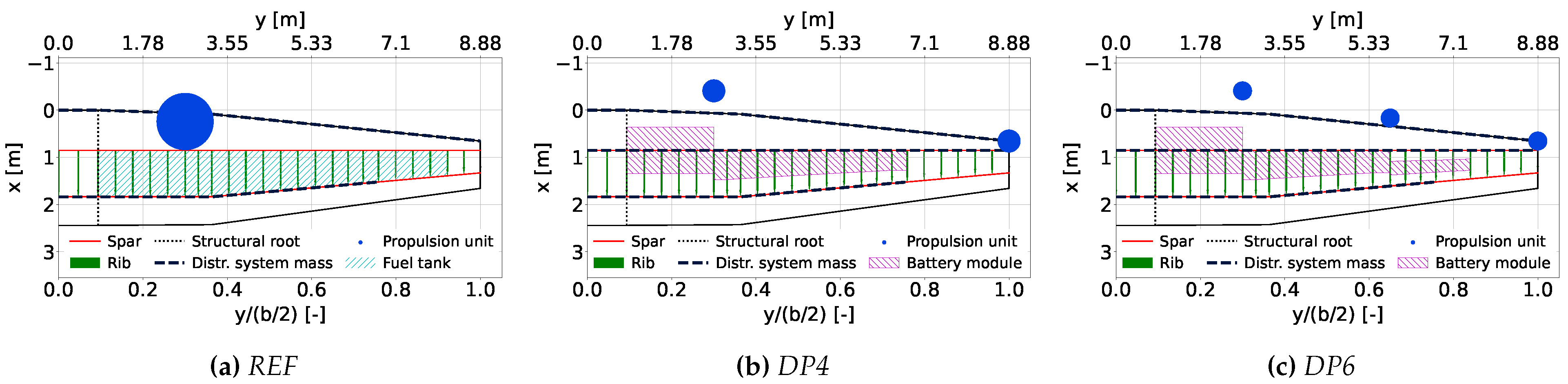
The semi-tapered cantilever wing of the reference aircraft has a full span of 17.8 m and a reference area of 34.4 m2 with an aspect ratio of 9.2. For the reference aircraft, the mass and stiffness properties of the aluminum wing box were determined based on the structural sizing and mass estimation methods developed by Elham [3] and Torenbeek [4], as described in detail in [1]. 
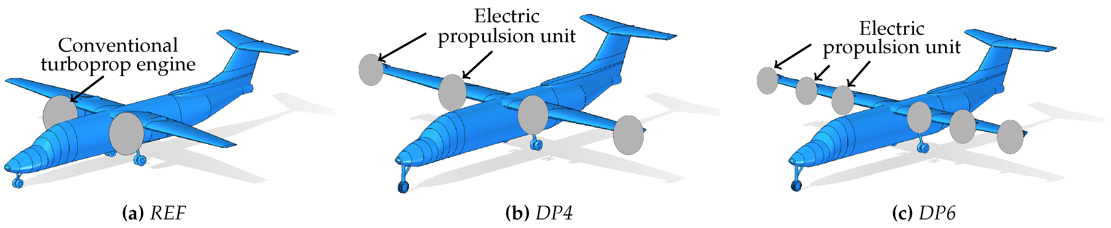
Figure 2 shows a schematic of the wing platform, primary structure, and location of all other masses considered for each configuration. The heavy conventional turboprop engine with a mass of 576.2 kg is mounted on the inner wing at 30% of the half span and 8% of the local chord length relative to the leading edge. The fuel tank extends from the structural root at 9.3% to 92.2% of the half span. A retrofit scenario is assumed by removing the conventional fuel-powered propulsion system and integrating the distributed electric propulsion and battery modules into the wing structure. This alters the total mass and mass distribution of the wing, whereas the stiffness properties of the primary structure remain unchanged. The mass and distribution of the propulsion system and the battery modules for the electric configurations were also defined in the previous work [1]. Each electric propulsion unit, comprising the propeller, electric engine, and switch, weighs 90.9 kg for the DP4 and 61.3 kg for the DP6 configuration. These concentrated masses are located near the leading edge at 30%, 65%, and 100% of the half span.
The mass breakdown of the wing and the eigenfrequencies of its first bending and torsional modes are provided in Table 1. The powertrain mass includes the mass of the propulsion units and other powertrain components, such as electric cables. The mode shapes and eigenfrequencies are determined by modal analysis of the wing structure idealized as a beam stick model in the finite element software MSC Nastran (https://hexagon.com/products/product-groups/computer-aided-engineering-software/msc-nastran accessed on 1 March 2025). The impact of the retrofitted powertrain on the modal properties of the wing is evident from the eigenfrequencies of the first bending and torsion mode of the wing structure. Despite a similar total wing mass for all three aircrafts, these eigenfrequencies are significantly lower for the wings with integrated distributed electric propulsion. More detailed information about the mass distribution and breakdown as well as the modal properties is given in [1].

2.2. Load Cases and Load Spectrum

The load cases typically occurring in service are defined based on the detailed ground–air–ground (GAG) cycle as described by Grover [5]. 
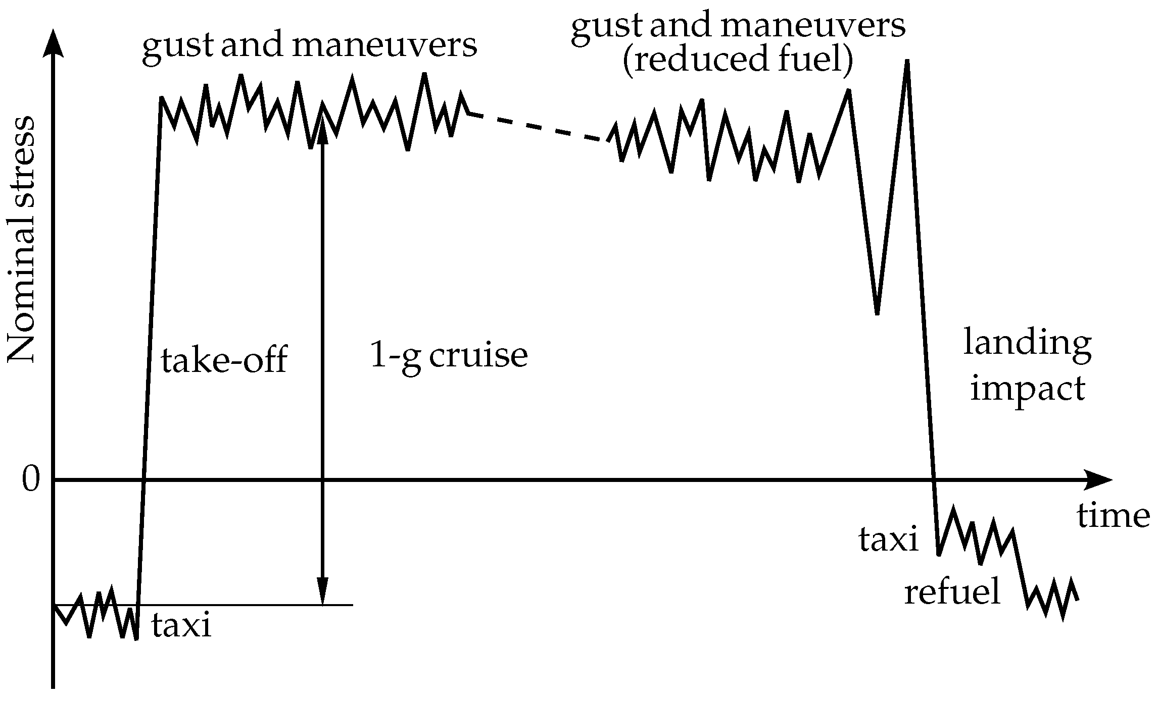
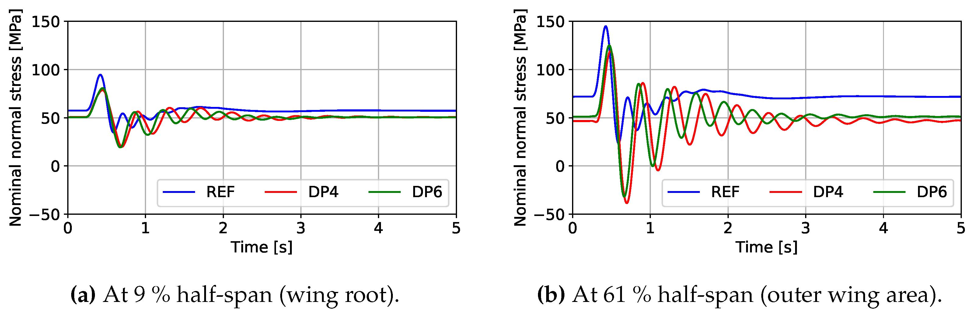
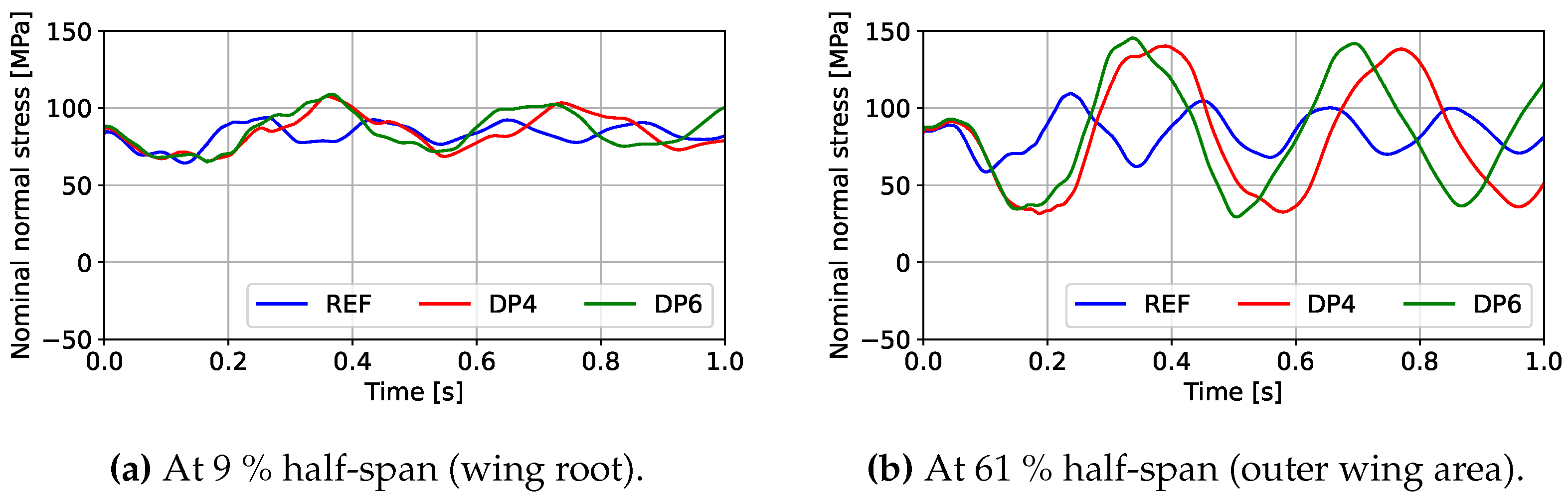
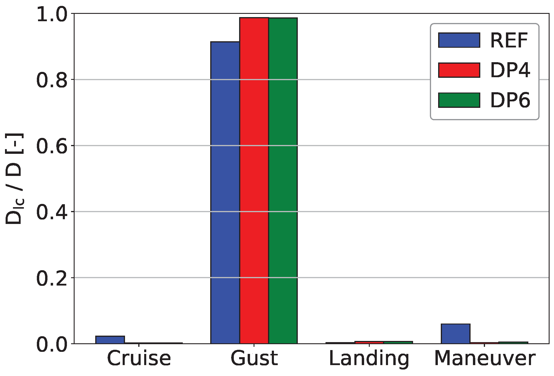
Figure 3 qualitatively shows the variation IN the nominal normal stresses in a lower skin panel of the wing structure over time for one GAG cycle. The following load cases are considered in this work for the fatigue analysis: 1-g cruise (relative to the ground static case), gusts (positive and negative vertical 1-cos gust), maneuvers (pull up and push over), and landing impacts (symmetric, no roll angle). Fatigue from cyclic loading is particularly relevant for the lower skin panels of the wing which during flight are almost permanently subjected to tensile stresses due to the upward bending of the wing as a result of the aerodynamic lift forces. The mostly constant positive mean stress (tension), superimposed by cyclic stresses induced by disturbances, is critical from a fatigue point of view. During taxiing, the mean stress in the lower skin panels is negative (compression) and no contribution to the accumulated damage is reported in the analysis of Grover [5]. Therefore, taxiing loads are not considered in this fatigue analysis.
Statistical data recorded on a fleet of original Beechcraft 1900D aircrafts during operational service [6] were used to define four reference missions for assessing the fatigue behavior of the wing for each aircraft configuration. The reference missions, as provided in Table 2, were chosen to cover 90% of the flight missions and conditions in terms of distance, altitude, and speed. For each reference mission, only cruise conditions were assumed with constant altitude, speed, and aircraft mass, neglecting a reduction in fuel mass during the flight mission. The consideration of different cruise flight conditions ensures that overall, varying aerodynamic loads and aeroelastic behavior of the wing are accounted for.
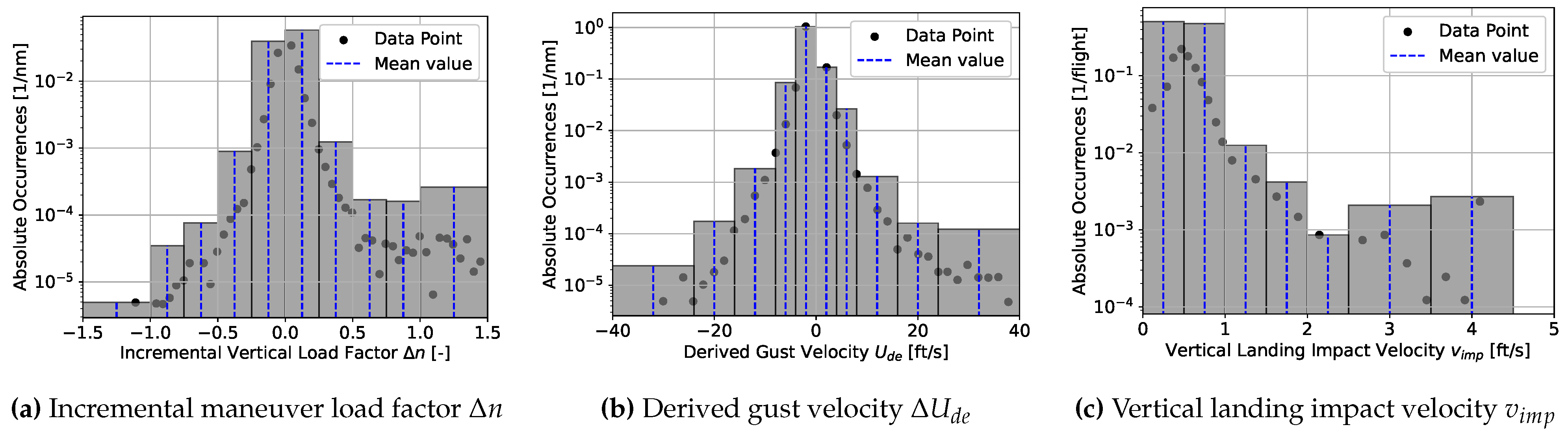
Three load case-specific parameters (incremental maneuver load factor Δ n for maneuvers, derived gust velocity Δ U d e for gusts, and vertical landing impact velocity v i m p for landing impacts) as well as their statistical frequency of occurrence per flight and mission were determined and varied based on the referenced statistical data for actual operational flight and ground loads for the Beechcraft 1900D fleet [6]. To keep the computational effort acceptable, the extensive statistical data were discretized into bins. For example, Figure 4 illustrates the discretization of the incremental maneuver load factor and the derived gust velocity at the flight level between 14,500 and 19,500 ft (for mission 3 at a cruise altitude of 17,000 ft), as well as the vertical landing impact velocity. The data points represent the total occurrence of the respective parameter value. For each bin, the mean value of the bin edges was used as the representative value for the load case. In addition to the four 1-g cases, this discretization results in a total number of ten different gust and maneuver load cases for each reference mission, and seven different landing impact load cases. The total number of occurrences of each load was defined as the sum of all data points inside the respective bin.

2.3. Modeling Approaches and Calculation Methods

The primary structure is an aluminum wing box consisting of skin panels (lower and upper) and spar webs (front and rear). It is idealized as a beam stick model along its elastic axis and discretized by 26 beam elements per half wing. The mass distribution is modeled using the lumped mass matrix for the wing structure, fuel, and batteries, considering additional concentrated masses for the propulsion units and other system components. The structural damping of the wing is modeled with a modal damping of 2% for all modes.
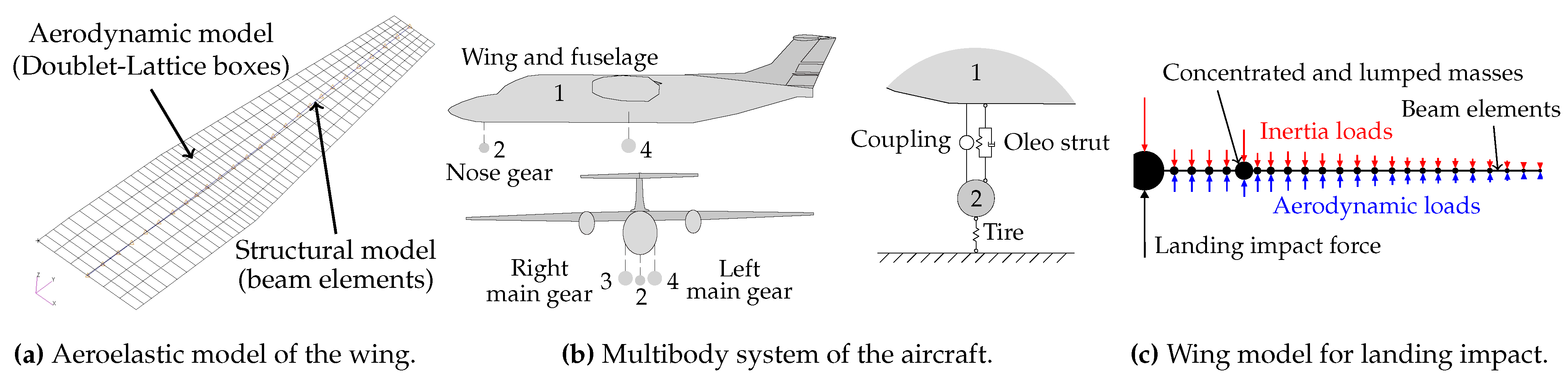
The analysis of the flight load cases is performed by finite element analysis with MSC Nastran. The aerodynamic loads are computed based on the Doublet Lattice method. The coupling of the aerodynamic and structural model shown in Figure 5a is realized via finite beam splines. A fixed boundary condition is applied at the structural wing root. Assuming quasi-static behavior for maneuvers, static aeroelastic analyses (SOL 144) for the 1-g cruise and maneuver load cases are conducted. For the gust load cases, a dynamic aeroelastic analysis (SOL 146) of vertical 1-cos gusts defined according to CS 23.333 [7] is performed. The total response is obtained by superposition with the solution of the 1-g cruise load case.
The landing impact load case is analyzed based on a dynamic response analysis implemented as a Python algorithm. First, the aircraft is modeled as a multibody system, see Figure 5b, with rigid bodies connected to each other via spring, damper, and coupling elements. An analytical model according to Milwitzky and Cook [8] is used to idealize the oleo-pneumatic landing gear to compute the time-dependent impact forces. The pitch angle of the aircraft is set to 3 ° as the average value in operational service according to the statistical data [6]. Only symmetric landing load cases are considered in this study.
As a second step, the calculated landing impact loads are applied to the structural model of the wing depicted in Figure 5c. The transient loads are applied at the fuselage center node. The dynamic response of the wing is obtained by modal analysis in combination with the phase plane method. The dynamic loads acting on the wing are calculated by implementation of the Williams method [9]. The aerodynamic loads are assumed to be constant during the landing impact phase and equal to the landing weight of the aircraft. Again, the total solution is obtained by the superposition of the static and dynamic solution.
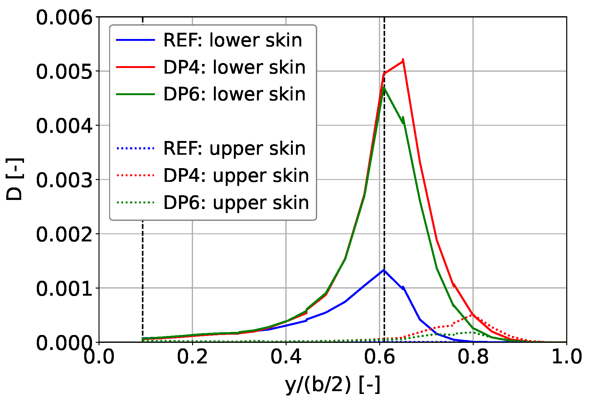
The fatigue analysis is conducted for the skin panels of the wing box. The alloy is assumed to be AL2024-T3 for the lower skin panels and AL7075-T6 for the upper panels. The rainflow counting method is used to discretize and determine load cycles as a combination of, firstly, value pairs of mean stress and stress amplitude, and secondly, their frequency of occurrences over the assumed service life. Considering elastic behavior and a safe life approach, the damage for each load cycle is calculated by the Palmgren–Miner rule yielding the damage parameter D. The cumulative fatigue damage is obtained by summation of the damage for all load cycles and indicates failure for D i 1 . The S-N curves for the aluminum alloys were taken from the handbook MIL-HDBK-5J [10]. The allowable stresses consider a notch factor K t of 2.0 to approximate the effect of stress raisers, such as holes and rivets, which are paramount for the fatigue analysis but cannot be captured by the beam model. To adjust the S-N curves for varying mean stresses, the Walker equation [11] is used and calibrated by the material data given in the referenced handbook.

3. Results and Discussion

This section presents the results of the stress and fatigue analysis for the three investigated aircraft configurations REF, DP4, and DP6. The calculation of the accumulated damage D is based on a number of 10,000 flights, taking into account the statistical frequency of occurrence of the defined reference missions and load cases, as described in Section 2.2. As all load cases are symmetric, the results are depicted only for the right wing.

3.1. Stress Analysis

To highlight the impact of the integrated distributed propulsion on the normal stresses in the skin panels due to increased bending deformation of the wing, this section focuses on critical load cases. As a result of the additional inertia loads induced by the wingtip-mounted engines, the changes are most pronounced for the transient load cases (gust and landing impact). The results for the static load cases (1-g cruise and maneuver) are not outlined. In this study, the lower skin panels are critical with regard to fatigue, and hence only the stresses in the lower panels are discussed. Two characteristic wing sections are assessed in detail: at the structural root at 9% half span, where the maximum bending moment occurs, and in the outer wing area at 61% half span, where the most severe stresses concerning fatigue damage accumulation are observed.
Figure 6 shows the time-dependent nominal normal stresses in the lower skin panel of the wing for a positive gust load case. At the wing root, no substantial change in the stress amplitudes is observed for the electric configurations compared to the reference configuration. In contrast, in the outer wing area, the stress amplitudes are significantly increased for these two aircrafts. Beyond the first peak, the stress amplitudes are substantially higher compared to the reference configuration. The wings of the DP configurations exhibit a notably longer decay duration of the oscillations. This lower damping of the wings with distributed electric propulsion is a result of the reduced eigenfrequencies of the wings. The lower eigenfrequencies lead to a reduction in the deflection speed of the wing following a gust and thus also to a reduction in the aerodynamic damping forces.
Figure 7 compares the stresses in the lower skin panel at the same wing sections for a landing load case. It shows similar trends to those observed for gusts. The increase in stress amplitudes is more pronounced in the outer wing than at the wing root when comparing the electric configurations with the reference. However, there is no difference in the damping of the oscillations. As the model for the landing impact analysis does not consider aeroelastic effects, the damping of the wing is identical for all aircraft configurations.

3.2. Fatigue Analysis

Figure 8 depicts the rainflow matrix for each aircraft configuration for the lower skin panels in the section at 61% half span. The rainflow matrix combines all extracted value pairs of mean stress and stress amplitude together with their frequency of occurrence. These data serve as input for the subsequent fatigue analysis based on the Palmgren–Miner rule. As indicated by the stress analysis, the plots show both higher values and occurrences of stress amplitudes over 10,000 flights for the DP configurations compared with the reference.
Figure 9 plots the accumulated damage over the wing span for both skin panels. As the evaluation of the absolute values of D is not meaningful due to the beam idealization, the relative comparison of the three aircraft configurations is focused. These results are consistent with the results of the stress analysis. In general, the lower skin panels are subjected to significantly higher fatigue damage than the upper panels, and the most damage is accumulated in the outer area of the wing. When comparing all configurations, the differences near the wing root are negligible, whereas in the outer wing area, the accumulated damage is substantially higher for the electric configurations. The examined section at 61% half span is one of the most critical areas of this wing, showing an increase in the accumulated damage by 272% for DP4 and 254% for DP6 compared with the reference.
Figure 10 shows the accumulated damage for each load case group as a fraction of the total damage for the lower skin panels in the section at 61% half span. In this critical section, the gust load cases account for more than 90% of the accumulated damage, being by far the major contributor to fatigue damage for all three configurations. The static load cases account for a modest share of the damage for the reference but are negligible for the electric configurations. The damage induced by landing impacts is marginal for all aircrafts.

4. Conclusions

This paper assesses the fatigue behavior of wings with distributed electric propulsion based on a retrofit scenario of a 19-seater commuter aircraft. A significant increase in the accumulated damage over 10,000 flights was observed compared with a wing structure of a conventional aircraft, particularly in the outer wing area. The increased fatigue damage can be attributed to the increased stress amplitudes and significantly lower damping of the structural vibrations upon transient gust loads. This is amplified by the fact that the gust load case is the dominant load case for fatigue for all aircraft configurations studied in this paper. The presented results indicate that the integration of distributed electric propulsion has a substantial impact on the fatigue behavior of wing structures. Fatigue is more critical for wings with distributed electric propulsion, and presumably has implications for the structural design and maintenance procedures of future electric aircrafts.
To further develop the understanding of the fatigue behavior of wings with distributed electric propulsion, future work should include a random response analysis for continuous turbulence, extending the present analysis of discrete gust load cases. Furthermore, a fundamental understanding of the impact of distributed propulsion on aerodynamic damping is necessary. In the present analysis, only the mass properties of the wing were affected by the integration of distributed electric propulsion. No aerodynamic interaction between the propellers and the wing was considered. In further studies, the aerodynamic propeller–wing interaction should be investigated to fully understand and evaluate the influence of the distributed electric propulsion on the aeroelastic behavior of the wing.

Author Contributions

Conceptualization, L.K., M.S. and K.-U.S.; methodology, L.K. and M.S.; software, L.K. and M.S.; validation, L.K. and M.S.; formal analysis, L.K. and M.S.; investigation, L.K. and M.S.; resources, K.-U.S.; data curation, L.K.; writing—original draft preparation, L.K. and M.S.; writing—review and editing, K.-U.S.; visualization, L.K. and M.S.; supervision, K.-U.S.; project administration, K.-U.S. All authors have read and agreed to the published version of the manuscript.

Funding

The results described in this paper were produced within the German national project ZeroCloud (grant number: 20E2231), which is funded by the sixth call in the aeronautical research program (LuFo VI) of the German Federal Ministry for Economic Affairs and Climate Action.

Institutional Review Board Statement

Not applicable.

Informed Consent Statement

Not applicable.

Data Availability Statement

The raw data supporting the conclusions of this article will be made available by the authors upon request.

Conflicts of Interest

The authors declare no conflicts of interest.

References

  1. Schubert, M.; Dafnis, A.; Schröder, K.-U. On the aeroelastic behavior of wings with distributed propulsion: Simple retrofit or structural modification. In Proceedings of the 19th International Forum on Aeroelasticity and Structural Dynamics, Madrid, Spain, 13–17 June 2022. [Google Scholar]
  2. Schubert, M.; Dafnis, A.; Schröder, K.-U. Gust and landing impacts as critical load cases for wings with distributed propulsion. J. Phys. Conf. Ser. 2023, 2526, 012001. [Google Scholar] [CrossRef]
  3. Elham, A.; La Rocca, G.; van Tooren, M.J.L. Development and implementation of an advanced, design-sensitive method for wing weight estimation. Aerosp. Sci. Technol. 2013, 29, 100–113. [Google Scholar] [CrossRef]
  4. Torenbeek, E. Advanced Aircraft Design: Conceptual Design, Analysis and Optimization of Subsonic Civil Airplanes; John Wiley & Sons: Hoboken, NJ, USA, 2013. [Google Scholar]
  5. Grover, H.J. Fatigue of Aircraft Structures; US Government Printing Office: Washington, DC, USA, 1967. [Google Scholar]
  6. Federal Aviation Administration. Statistical Loads Analysis of BE-1900D in Commuter Operation; Federal Aviation Administration: Washington, DC, USA, 2017. [Google Scholar]
  7. European Union Aviation Safety Agency. Certification Specifications for Normal-Category Aeroplanes (CS-23): Amendment 5; European Union Aviation Safety Agency: Cologne, Germany, 2017. [Google Scholar]
  8. Milwitzky, B.; Cook, F.E. Analysis of Landing-Gear Behavior; NACA-TN-2755; National Advisory Committee for Aeronautics: Washington, DC, USA, 1952. [Google Scholar]
  9. Williams, D. The Principles Underlying the Dynamic Stressing of Aeroplanes. Aeronaut. J. 1951, 55, 362–381. [Google Scholar] [CrossRef]
  10. Department of Defense. MIL-HDBK-5J: Metallic Materials and Elements for Aerospace Vehicle Structures; Department of Defense: Arlington County, VA, USA, 2003. [Google Scholar]
  11. Dowling, N.E.; Prasad, K.S.; Narayanasamy, R. Mechanical Behavior of Materials: Engineering Methods for Deformation, Fracture, and Fatigue, 5th ed.; Global, Ed.; Pearson: Boston, MA, USA, 2019. [Google Scholar]
Figure 1. Illustration of 19-seater aircraft: reference configuration (a) and retrofitted configurations with distributed propulsion (b,c).
Engproc 90 00058 g001
Figure 2. Schematic illustration of the right wing for the three investigated aircarft configurations.
Engproc 90 00058 g002
Figure 3. Qualitative representation of the nominal stress levels acting in the lower skin panel of the wing during one ground–air–ground cycle, based on Grover [5].
Engproc 90 00058 g003
Figure 4. Discretization of the statistical data for actual operational flight and ground loads for the Beechcraft 1900D (excerpt).
Engproc 90 00058 g004
Figure 5. Modeling approaches for the gust (a) and landing impact analysis (b,c).
Engproc 90 00058 g005
Figure 6. Nominal normal stresses in the lower skin at (a) 9% half span and (b) 61% half span for the gust load case at h = 17,000 ft and M a = 0.419 with Δ U d e = 10 ft/s.
Engproc 90 00058 g006
Figure 7. Nominal normal stresses in the lower skin at (a) 9% half span and (b) 61% half span for the landing load case with v i m p = 1.75 ft/s.
Engproc 90 00058 g007
Figure 8. Rainflow matrix for the lower skin panel at 61% half span for all three aircraft configurations.
Engproc 90 00058 g008
Figure 9. Accumulated damage D in the lower and upper skin panels over the wing span.
Engproc 90 00058 g009
Figure 10. Load case-specific fractions of accum. damage in the lower skin panels at 61% half span.
Engproc 90 00058 g010
Table 1. Mass breakdown and characteristic eigenfrequencies of the wing for all three aircraft configurations (mass units in [kg] and eigenfrequency units in [Hz]).
Mass GroupREF (50% fuel)DP4DP6
Wing structure344.0332.0334.0
Powertrain607.3246.0242.9
Fuel528.2--
Batteries-987.3972.2
Total1479.51565.31549.1
Mode ShapeREF (50% fuel)DP4DP6
1. bending mode4.02.52.7
1. torsion mode37.117.115.9
Table 2. Reference missions with varying cruise flight conditions, defined based on [6].
Mission IDFlight Distance [nm]Cruise Altitude [ft]Cruise Mach Number [-]Percentage of Flights [%]
110070000.37028.1
215012,0000.39827.9
320017,0000.41926.1
425022,0000.44217.9
Disclaimer/Publisher’s Note: The statements, opinions and data contained in all publications are solely those of the individual author(s) and contributor(s) and not of MDPI and/or the editor(s). MDPI and/or the editor(s) disclaim responsibility for any injury to people or property resulting from any ideas, methods, instructions or products referred to in the content.

