1. Introduction
The integration of next-generation engines, including advanced concepts such as Composite Cycle Engines [
1,
2], is set to revolutionize the field of aviation by 2035+. These engines promise to significantly enhance fuel efficiency and reduce emissions [
3,
4], aligning with the industry’s long-term sustainability goals. However, these technological advancements bring forth new challenges in aircraft design, particularly concerning aerodynamic efficiency and structural integration. As engine sizes increase with higher bypass ratios and complex configurations [
5,
6,
7], their placement within the airframe must be carefully reconsidered. The nacelle, which houses the engine, becomes a focal point for aerodynamic interference, adding drag that can degrade the overall aircraft performance if not properly managed. Available publications from ONERA and NASA [
8,
9] indicate that high BPR engine integration can have a double-digit impact on total aircraft drag, highlighting the importance of addressing this issue. In this context, understanding the nacelle drag increment—specifically the increase in drag attributed to engine integration—is essential to optimizing the aerodynamic profile of future aircraft.
Nacelle drag comprises several components, such as profile isolated nacelle drag and interference drag. Interference drag represents a substantial portion when the nacelle interacts with other aircraft structures, such as wings. Nacelle integration on modern aircraft can result in a double-digit percentage increase in total drag, underscoring the importance of accurately modeling and predicting this effect [
8,
9]. Previous research, such as the methodologies presented by Raymer and Roskam [
10,
11], has provided a foundation for understanding interference factors through empirical methods. These semi-empirical approaches offer valuable insights by incorporating statistical correlations and design experience. However, these methods are limited in their applicability to modern nacelle configurations, which involve new geometrical and aerodynamic parameters unique to advanced engine technologies.
The current study aims to develop a modeling tool that addresses these limitations, enabling a more refined assessment of nacelle-interference drag. This tool is designed to conduct parametric analyses, considering variations in nacelle size (diameter and length) and placement (longitudinal and vertical positions) relative to the wing [
12,
13]. Unlike previous models that apply a generalized approach, the proposed tool combines several existing semi-empirical methods customized for a broader range of design configurations. By analyzing interference factors at different positions, the tool provides detailed insight into how specific configurations affect drag. This facilitates targeted design adjustments to minimize drag increment, thereby improving fuel efficiency and advancing towards more sustainable aviation.
In summary, the study addresses a critical gap in nacelle drag prediction by developing a flexible, parametric tool that quantifies the aerodynamic impact of nacelle integration under various design conditions. The results offer valuable insights for engineers seeking to integrate large, high-bypass engines effectively, with the goal of enhancing aircraft performance through reduced interference drag.
2. Tools and Methods
The methodology for this study is structured to provide an assessment of nacelle drag increment due to new engine installations on future aircraft. The methodology is divided into four sections: an overview of the nacelle drag breakdown. This is then followed by the presentation of existing methodologies for the nacelle interference drag calculation, underlying their limitations. Moving forward, the proposed tool is presented including the inputs and key parameters, such as nacelle placement and size, which are essential for parametric drag analysis. Finally, a description of the design space and case studies, describing the configurations analyzed.
2.1. Nacelle Drag Breakdown
Focusing on the nacelle, the drag coefficient (C
Do, nacelle) is separated into two key components [
10]:
where C
Do, Isolated nacelle represents the isolated profile drag of the nacelle, accounting for the drag based solely on its shape and dimensions and C
DINT denotes the interference drag, which is caused by the aerodynamic interaction between the nacelle and other components, particularly the wing. Both of them are scaled with the wing reference area S
ref.
By isolating these components, the aerodynamic impact of nacelle installation can effectively be assessed. These parameters provide insight into how the nacelle’s design and position influences total drag, offering a basis for optimizing nacelle integration to reduce aerodynamic penalties.
Through this breakdown of drag components, this study aims to capture the specific contributions of nacelle installation on total aircraft drag, allowing for a more detailed understanding of how new engine technologies affect aircraft performance.
2.2. Existing Methodologies
Interference factors are typically calculated using statistical correlations and semi-empirical relationships. Standard aircraft design literature [
10] provides some rules of thumb. Raymer method suggests an interference factor of 1.5 for a nacelle mounted directly on the fuselage or wing, while one mounted less than about one diameter away might be closer to 1.3. Finally, a nacelle mounted farther away might be closer to
1.
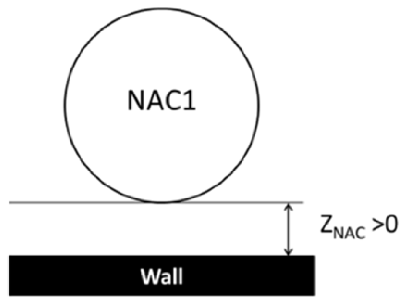
The interpolated method [
8] based on the Raymer standard method presents a linear evaluation of the interference factor (Q
N) based on the vertical position of the nacelle (
Figure 1), as presented below.
These individual simplified methods for the installation drag assessment do not provide the accuracy needed for advanced engine designs as they are limited in their inputs, with interference drag affected solely by the z/D parameter. This restricts their ability to capture the full range of aerodynamic interactions, which is essential for accurately evaluating nacelle integration in modern configurations.
2.3. Proposed Tool
The analytical tool developed for this study calculates interference drag by assessing the aerodynamic interaction between the nacelle and the wing, integrating theoretical and semi-empirical models [
14,
15], allowing for parametric studies on interference drag. The interference drag results from the physical separation and relative placement of the nacelle and wing contributing significantly to the total drag experienced by the aircraft. This factor becomes increasingly critical as engine sizes grow and higher bypass ratio (BPR) engines are implemented in modern and next-generation aircraft. Proper assessment and management of interference drag are thus essential for achieving optimal aerodynamic performance.
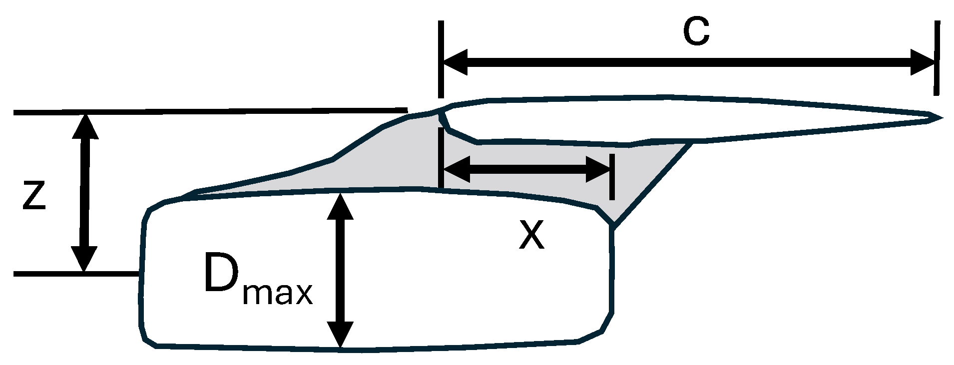
The key tool inputs are divided into three categories: position, size, and aircraft velocity. These inputs provide a comprehensive basis for evaluating how nacelle integration affects drag. Position parameters include the longitudinal (chordwise) and vertical positions of the nacelle, as illustrated in
Figure 2. The longitudinal position influences interference drag by adjusting the nacelle’s placement forward or backward, affecting the wake interaction with the wing. The vertical position, on the other hand, determines the nacelle’s distance from the wing. Adjustments in vertical placement affect the intensity of interference drag by changing the flow characteristics and pressure distribution around the nacelle and wing. Nacelle size, specifically diameter (D
max) and length, is also a critical parameter, as variations in these dimensions significantly influence form and interference drag, especially for larger, next-generation engines. Additionally, the tool incorporates cruise Mach number, which affects drag behavior based on speed, ensuring that predictions reflect realistic operating conditions and Mach design (M
DESIGN). The calculation of M
DESIGN is carried out using the Delta method, an empirical drag estimation technique [
16] which covers a wide range of aircraft and airfoil types, allowing for Mach numbers up to 2. M
DESIGN calculation depends on C
L,DES and wing geometry characteristics like aspect ratio (AR), sweep angle (Λ), and thickness ratio(t/c). This approach allows the tool to generate accurate and context-sensitive predictions for various flight conditions, ensuring that interference drag calculations are aligned with practical design requirements.
2.4. Design Space and Case Studies
This study evaluates nacelle drag increment across various configurations, focusing on potential future aircraft equipped with advanced engine technologies. Within the MINIMAL project, three reference aircraft platforms were identified for assessment, namely, short-range, medium-range, and long-range platforms. For this study, emphasis is placed on the medium-range A321XLR-class EIS2035+, representing a medium-range aircraft with extended capabilities to reach 4200 NM at its design payload in accordance with the MINIMAL aircraft scenario.
This study’s design space includes multiple nacelle configurations to analyze the drag increment across different sizing and positioning scenarios. Specifically, three modifications are examined: a 10% increase in nacelle diameter; a 10% increase in nacelle length; and a combined increase of 10% in both diameter and length (
Table 1). This study’s design space was developed based on aircraft models provided by partners in MINIMAL’s consortium, where each aircraft configuration was redesigned to ensure flyability, incorporating minor adjustments to the wing and nacelle dimensions and positions. The longitudinal positioning (x/c) is set to zero for every configuration. The baseline platform represents an aircraft set to enter service in 2035+, where the trend is to position the nacelle’s aft-most point level with the wing’s leading edge. By examining these configurations, the study evaluates how specific changes in nacelle characteristics influence overall drag, contributing valuable insights for optimizing engine placement.
3. Results
Initial analyses were conducted using the Raymer standard method, which assesses interference drag based on vertical positioning (z/D) alone. This approach provided only two distinct interference drag values for various nacelle locations and sizes (
Figure 3a), indicating significant limitations in sensitivities for diverse engine placement scenarios. This restriction was evident when examining different nacelle configurations, where Raymer’s method failed to account for subtle variations in drag changes due to complex nacelle placements. The interpolation method built on Raymer’s methodology showed a linear decrease in interference drag as the nacelle’s distance from the wing increased; however, this method also remained dependent solely on vertical positioning (z/D), as shown in the
Figure 3b, limiting its application for comprehensive design assessments. Figures illustrating these trends highlight that while existing methods provide a baseline understanding, they do not capture the full range of aerodynamic interactions necessary for modern engine design.
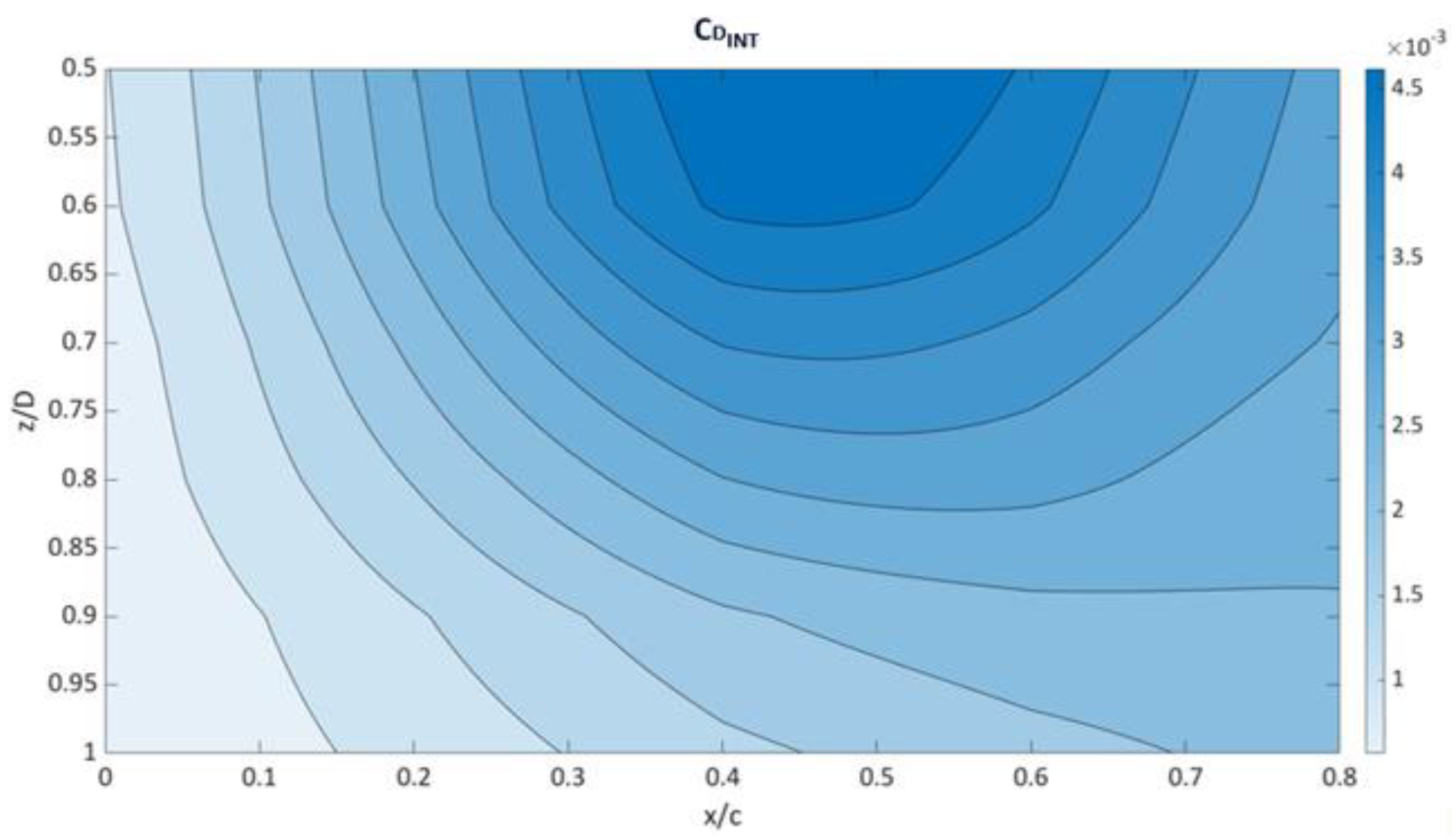
Using the proposed model, the interference drag component C
DINT was calculated across various configurations on the medium-range EIS2035+ baseline aircraft. The interference drag was assessed as a function of vertical (z/D) and longitudinal (x/c) positioning, as shown in
Figure 4. While the model includes predictions for longitudinal positions (x/c) up to 0.8, values beyond x/c = 0.4 are not particularly relevant for MINIMAL platforms. These extended results are primarily included to demonstrate the flexibility and capability of the analytical method. The results demonstrate that interference drag varies significantly with nacelle placement, with higher drag values observed for configurations where the nacelle is positioned closer to the wing in both vertical and longitudinal directions. Notably, placing the nacelle lower or further forward has a more pronounced influence on drag. However, the optimal placement involves a trade-off between nacelle interference drag and the structural mass of the pylon and wing. From an aerodynamic perspective, the nacelle should ideally be placed farther from the wing to minimize interference drag. Conversely, from a structural standpoint, positioning the nacelle closer to the wing is advantageous for reducing pylon and wing structural mass. This analysis provides valuable insights for balancing these competing considerations to achieve an optimal configuration.
The detailed breakdown of the nacelle installation drag across different configurations is presented in
Table 2. Using an in-house aerodynamic module based on a combination of semi-empirical methodologies [
10,
11], the form drag of the isolated nacelle is calculated, and by adding the interference drag from the proposed tool, the total nacelle drag occurs. For the baseline configuration, the isolated nacelle drag coefficient was found to be 0.0026, while the interference drag coefficient was 0.0011, resulting in a total nacelle drag coefficient of 0.0037. A 10% increase in nacelle diameter led to an increase in interference drag to 0.0014, yielding a total drag coefficient of 0.0042. When the nacelle length was increased by 10%, the total drag rose to 0.0040. The most significant drag coefficient, 0.0045, was observed when both diameter and length were increased by 10%. These findings illustrate that both nacelle size and positioning are critical factors influencing total drag and should be considered in early-stage design evaluations.
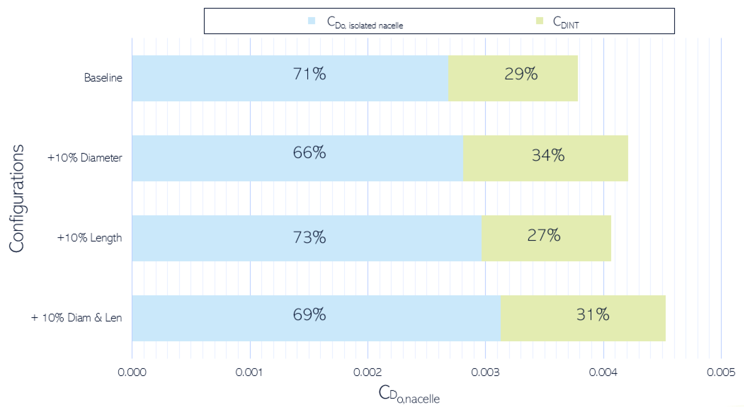
The role of interference drag in overall nacelle installation drag is further detailed in
Figure 5, a bar chart displaying the proportion of interference drag across various configurations. The baseline configuration showed that interference drag accounted for 29% of the installation drag, while the remaining 71% was isolated nacelle drag. A 10% increase in nacelle diameter raised the contribution of interference drag to 34%, demonstrating its heightened sensitivity to changes in nacelle size. Conversely, a 10% increase in nacelle length led to a slight reduction in the interference drag contribution to 27%. When both diameter and length were increased, the interference drag accounted for 31% of the total drag. These observations emphasize that interference drag plays a significant role in the overall aerodynamic performance of the aircraft, particularly when larger nacelles are involved. The results suggest that careful consideration of both nacelle sizing and placement can lead to optimized aerodynamic designs, minimizing drag penalties.
The comparison of interference factor values calculated using the Raymer standard and interpolated methods versus the proposed method are presented in the
Table 3. The results show that using the proposed approach lead to a more detailed prediction of interference drag based on nacelle dimensions and positioning. Furthermore, the simplified methods tend to overestimate interference drag since they were derived based on older aircraft which featured longer nacelles with smaller diameters positioned much closer to the wing in both longitudinal and vertical directions.
Validation of the proposed tool was conducted by comparing the results with benchmark data from ONERA and NASA, which included results from wind tunnel tests and computational fluid dynamics (CFD) analyses.
Table 4 presents the C
D without the nacelle and the C
D increment due to engine installation, illustrating that the proposed model’s predictions align closely with established data. For example, at a cruise Mach number of 0.78, the baseline nacelle configuration showed a total drag increment of approximately 10.1%, consistent with benchmark findings. The tool’s accuracy extended to configurations with increased diameter and length, where predicted drag increments were 11.2%, 10.8%, and 12.1% for diameter, length, and combined increases, respectively. These comparisons validate the proposed model as an effective approach for estimating nacelle drag impacts, offering more detailed and reliable predictions than traditional methods.
4. Conclusions
The proposed analytical tool successfully bridges the gap between simplified methods and detailed, reliable drag prediction by incorporating key parameters such as vertical and longitudinal positioning. This tool provides a more accurate assessment of nacelle drag impacts, offering an effective solution for optimizing nacelle placement during the design phase. The results align closely with benchmark data from CFD analyses and previous empirical studies by ONERA and NASA, confirming the reliability of the proposed approach for nacelle drag prediction.
The study’s findings underscore that nacelle integration plays a significant role in overall aircraft drag, with installation drag potentially increasing by up to 12% for larger engine designs, which is particularly interesting for future aircraft concepts. The comprehensive analysis using the developed tool confirmed that interference drag is highly influenced by nacelle placement and size, making it a crucial factor in total drag estimation. Parametric studies demonstrate that the interference factor, dependent on both nacelle positioning and sizing, significantly impacts total drag.
The results show that interference drag contributes substantially to total nacelle installation drag. For the baseline aircraft, interference drag accounts for approximately 29% of the total drag of the nacelle, and this proportion can increase up to 34% when the nacelle diameter is enlarged by 10%. Such findings highlight the pivotal role that interference drag plays in overall aerodynamic performance, particularly as nacelle dimensions increase. This study contributes valuable insights for the future design of aircraft with larger, next-generation engines, promoting strategies to mitigate drag and enhance fuel efficiency. The findings underline the importance of holistic nacelle placement evaluation, supporting advancements in aerodynamic performance and sustainable aviation.
The next steps of the current research will be focused on expanding the design space of the proposed methodology by exploring nacelle outlet longitudinal placements forward of the wing’s leading edge. This expanded analysis aims to capture additional aerodynamic effects and further refine nacelle integration strategies. Additionally, conducting detailed CFD simulations will be prioritized to validate and enhance the accuracy of the data generated by the proposed tool. These simulations will provide deeper insights into complex flow interactions and contribute to further optimizing nacelle placement, ultimately supporting the development of more efficient and environmentally sustainable aircraft designs.
Author Contributions
Conceptualization, O.Z. and P.P.; methodology, O.Z. and S.A.; software, O.Z.; validation, P.P. and K.Y.; investigation, O.Z.; resources, O.Z.; data curation, O.Z. and S.A.; writing—original draft preparation, O.Z. and S.A.; writing—review and editing, P.P. and K.Y.; visualization, O.Z. and S.A.; supervision, P.P.; project administration, K.Y.; funding acquisition, P.P. and K.Y. All authors have read and agreed to the published version of the manuscript.
Funding
Project co-funded by the European Union’s Horizon Europe Programme under the grant agreement n°101056863 and by the UK Research and Innovation (UKRI) funding guarantee under the project reference n° 10040930, 10053292 and 10039071.
Institutional Review Board Statement
Not applicable.
Informed Consent Statement
Not applicable.
Data Availability Statement
Data available on request due to restrictions related to the details of the baseline platform. The data presented in this study are available on request from the corresponding author.
Conflicts of Interest
The authors declare no conflicts of interest.
References
- Kaiser, S.; Kellermann, H.; Nickl, M.; Seitz, A. A Composite Cycle Engine Concept for Year 2050. In Proceedings of the 31st Congress of the International Council of the Aeronautical Sciences, Belo Horizonte, Brazil, 9–14 September 2018. [Google Scholar]
- Kaiser, S.; Schmitz, O.; Klingels, H. Aero Engine ConceptsBeyond2030: Part 2—The Free-Piston Composite Cycle Engine. J. Eng. Gas Turbines Power 2021, 143, 021002. [Google Scholar] [CrossRef]
- Saluja, H.S.; Yin, F.; Gangoli Rao, A.; Grewe, V. Effect of Engine Design Parameters on the Climate Impact of Aircraft: A Case Study Based on Short-Medium Range Mission. Aerospace 2023, 10, 1004. [Google Scholar] [CrossRef]
- Kaiser, S. Multidisciplinary Design of Aeronautical Composite Cycle Engines. Ph.D. Thesis, Technical University of Munich, Gothenburg, Sweden, 2020. [Google Scholar]
- Daly, M. (Ed.) Jane’s Aero-Engines, 28th ed.; IHS Global, Ltd.: Surrey, UK, 2010; pp. 28–30. [Google Scholar]
- Barbosa, F.C. Aircraft engine technology review -the pathways for an efficient, cleaner and quieter aviation industry, In Proceedings of the 2019 SAE Brasil Congress and Exhibition, São Paulo, Brazil, 14–18 October 2019; SAE International: Warrendale, PA, USA, 2020.
- Kozaczuk, K. Engine nacelles design—Problems and challenges. Proc. Inst. Mech. Eng. G J. Aerosp. Eng. 2017, 231, 2259–2265. [Google Scholar] [CrossRef]
- Moëns, F. A Fast Aerodynamic Model for Aircraft Multidisciplinary Design and Optimization Process. Aerospace 2023, 10, 7. [Google Scholar] [CrossRef]
- NASA. Installation Effect of Wing-Mounted Turbofan Nacelle-Pylons on a 1/17 Scale, Twin Engine, Low-Wing Transport Model; Technical Paper; NASA: Washington, DC, USA, 1992; Volume 3168.
- Raymer, D. Aircraft Design: A Conceptual Approach, 6th ed.; American Institute of Aeronautics and Astronautics: Reston, VA, USA, 2018. [Google Scholar]
- Roskam, J. Airplane Design, Part VII: Determination of Stability, Control and Performance Characteristics: FAR and Military Requirements; Roskam Aviation and Engineering Corp: Ottawa, ON, Canada, 2006. [Google Scholar]
- Hoheisel, H. Aerodynamic aspects of engine-aircraft integration of transport aircraft. Aerosp. Sci. Technol. 1997, 1, 475–487. [Google Scholar] [CrossRef]
- Rossow, C.C.; Godard, J.L.; Hoheisel, H.; Schmitt, V. Investigations of propulsion integration interference effects on a transport aircraft configuration. In Proceedings of the AIAA/SAE/ASME/ASEE, Nashville, TN, USA, 6–8 July 1992. paper no. AIAA 92-3097. [Google Scholar]
- Kroo, I. Aircraft Design: Synthesis and Analysis; Desktop Aeronautics, Inc.: Palo Alto, CA, USA, 2006. [Google Scholar]
- Montgomerie-Jensen, B.; Finch, B. Drag Prediction Methods for Subsonic Airplanes; Boeing document D6-24229; Chicago, IL, USA, 1970. [Google Scholar]
- Feagin, R.C.; Morrison, W.D. Delta Method, an Empirical Drag Buildup Technique. Technology Report; NASA-CR-151971; NASA: Washington, DC, USA, 1978.
| Disclaimer/Publisher’s Note: The statements, opinions and data contained in all publications are solely those of the individual author(s) and contributor(s) and not of MDPI and/or the editor(s). MDPI and/or the editor(s) disclaim responsibility for any injury to people or property resulting from any ideas, methods, instructions or products referred to in the content. |
© 2025 by the authors. Licensee MDPI, Basel, Switzerland. This article is an open access article distributed under the terms and conditions of the Creative Commons Attribution (CC BY) license (https://creativecommons.org/licenses/by/4.0/).


