Proceeding Paper

Novel Modeling Methodology for Thermal Evaluation of an Electrically Assisted High-Speed Turbomachine †

1
Faculty of Mechanical Engineering, Aristotle University of Thessaloniki, 54124 Thessaloniki, Greece
2
IHI Charging Systems International GmbH, 69126 Heidelberg, Germany
3
Silver Atena GmbH, 80995 Munich, Germany
*
Author to whom correspondence should be addressed.
Presented at the 14th EASN International Conference on “Innovation in Aviation & Space towards sustainability today & tomorrow”, Thessaloniki, Greece, 8–11 October 2024.
Eng. Proc. 2025, 90(1), 48; https://doi.org/10.3390/engproc2025090048
Published: 14 March 2025

Abstract

:
Hydrogen-based fuel-cell systems are a promising technology for reducing carbon footprint in the portfolio of future propulsion system concepts for small-range and regional aircraft In order to increase efficiency, the application of a turbo-charged air supply, using a compressor stage, a turbine stage, and an electric motor, has proven to be beneficial. This paper explores the thermal management aspects of a pioneering Electrified Turbo Charger designed for fuel-cell applications. A novel approach employing gas-cooling for the electric machine is investigated through simulation using an adiabatic Computational Fluid Dynamics (CFD) model. Bulk-flow-based Heat Transfer Coefficients (BHTCs) and temperatures are extracted from the CFD Analysis and serve as boundary conditions in a Solid Thermal model. Additionally, a 3D transient electromagnetic analysis is employed to assess losses in various components of the machine, which are then integrated into the 3D Solid Thermal Model. Initial evaluation of the temperature distribution is conducted, and subsequent analysis highlights uncertainties inherent in this methodology.

1. Introduction

1.1. Broader Context of Climate Change

Climate change and greenhouse gas emissions are known to be interdependent and are characterized as the main cause of our planet’s temperature rise, a problem that troubles the scientific community and society ultimately for the past decades [1,2,3,4]. After the Paris agreement, the United Nations Climate Change Commission (UNFCCC) set a long-term goal of keeping the temperature stable and not allowing it to exceed a 2 degrees Celsius increase compared to values before the industrial revolution [5,6]. According to this aim, the European Union has created a common hydrogen strategy that focuses on accelerating the production of clean hydrogen, decarbonizing its use, and creating a robust infrastructure and market around it [3]. According to IRENA [4], a realistic way of decreasing the CO2 emissions by 2050 is through six technological avenues, with one of them being hydrogen composing 10% of the energy mixture given that it is produced from renewables.
In more context, in the EU during 2018, around 3.8 gigatons of carbon dioxide were emitted, with the transport sector contributing around 29% of that value alone, with aviation contributing 4% of the sector total [4]. A hydrogen fuel-cell-powered propulsion system is considered to be a promising zero-emission system that can be applied to a small-range regional aircraft architecture, contributing to the sector’s decarbonization [5,6,7,8,9,10].

1.2. Background of a Charged Fuel-Cell System

A simplified fuel-cell system can be split into four subsystems. The hydrogen subsystem, the fuel-cell stack, the air subsystem, and the electric powertrain [11]. Focusing on the air subsystem, its main component is the electric turbomachine, which is composed of a compressor, a turbine, and an electric motor. The turbomachine is included in this system simply to increase the pressure of air that is needed from the fuel cell to support its electrochemical reaction. In more detail, the increase in air pressure leads to voltage gain and ultimately increases the power density of the system [5,11,12]. According to [5], the connection between the voltage gain and the pressure increase is described by:
Δ V g a i n = C l n P 2 P 1 ,
where: C is the voltage gain constant.
The machine investigated in this work was created using the main findings of Filsinger et al. [8], while introducing a novel concept of cooling and electric motor topology. The main aim, when designing the new charging system [13], was to unlock high-speed operation and reduce the manufacturing cost and complexity of the machine. Background information about the scope, mission, and layout of the investigated device, essential to the current paper, can be found at Rathke et al. [12].

1.3. Electric Machine Topologies for Electric Turbo-Compressors

Usually, the main motor topologies used by the industry in electric turbochargers are overlapping distributed [8,12,13] and non-overlapping concentrated configurations [9,10,14]. For the machine studied here, an alternative motor topology was chosen, the toroidal winding motor. In more detail, the motor of the machine is a non-slotted six-coil two-pole toroidal high-speed permanent magnet motor. This architecture was selected because it can achieve high-speed operation, creates low stator and rotor losses, has insignificant cogging torque, negligible torque ripples [15], and offers a great coil-area exposure to air. On the other hand, like all designs, it introduces some drawbacks. The AC (high-frequency) copper losses are expected to be high, with an additional concern that the housing in contact with the neighboring coils may create additional losses due to induced eddy currents. Furthermore, this topology has a relatively large air gap between the rotor and stator, which increases flux leakage and ultimately results in lower output torque when compared to other motor types [14,15,16,17,18].

1.4. Forced-Air Cooling Concept

The key idea when implementing the novel forced air-cooling concept of the machine’s components was forcing air to flow inside the electric motor, between the housing and the stator. The cooling flow was provided from the exit of the turbine passage. At maximum operating power, the temperature of the fuel-cell exhaust gases entering the turbine volute is approx. 75 °C, with a relative humidity close to saturation. One key design characteristic is distancing the housing from the windings–stator, thus reducing the induced eddy currents and creating an air passage that can be used for cooling purposes.

1.5. Thermal Evaluation Scheme

The temperature evaluation of the machine for high-power operation is of crucial importance, especially during the design phase. Moving away the housing from the coils reduces the induced losses (Borisavljevic et al. [17]) but also influences the flow field of the cooling air and the cooling capacity due to convection. To evaluate the temperature field, one can use conjugate heat transfer analysis, but the setup and computation load are time-consuming, especially for complicated geometries like the one under investigation. For this reason, a multistep approach was implemented using separated Computational Fluid Dynamics and Electromagnetic and Finite Elements Thermal analysis that share boundary conditions. At first, an adiabatic CFD simulation was conducted, which allowed the extraction of boundary conditions like wall temperature and bulk-flow-based heat transfer coefficients (BHTCs), according to a well-known method in the turbomachinery industry established by Karamavruc et al. [19]. Next, a transient electromagnetic analysis was used to calculate the electromagnetic losses of the machine. Finally, these data were integrated into the finite element thermal model, in which the whole machine was represented, and the temperature field was calculated. The methodology described offers significant time improvements compared to conjugate heat transfer, and the results presented here represent the maximum power operating point of the fuel-cell system being considered [12].

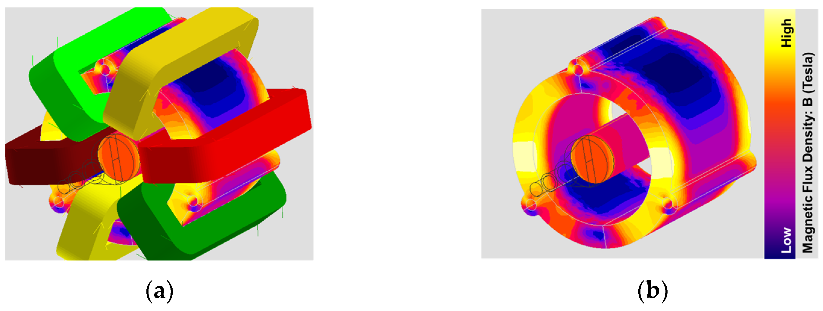
2. Electromagnetic Simulation

In order to evaluate the electromagnetic losses of the electric motor in the turbomachine and the amount of thermal load they produce, two transient electromagnetic models were created—a two-dimensional one and a three-dimensional one. For both models’ creation and calculation, the commercial package Altair FluxTM was used. The creation of eddy currents that occur in the machine’s components is a complicated phenomenon influenced by the three-dimensional geometric characteristics of the machine’s components [20]. Two-dimensional models cannot capture such effects, so the 3D one was created, and its results were compared against the results of the 2D model.
A non-meshed coils approach was implemented, including the winding heads, visible in Figure 1a. An end-winding effect was captured at the stator that was not previously predicted by the 2D model. In Figure 1b, a magnetic flux density spike in the stator near the excited end-winding was observed. This spike leads to increased stator losses. The explanation behind this effect is the leakage flux that passes through the air-window from the winding heads to the stator [20].
When comparing the 2D and 3D results at the maximum fuel-cell power operating point, the 3D model predicts 2% lower output torque but 325% higher stator losses and 56% higher housing losses. The considerably increased losses are mainly due to end-winding and 3D effects. On the other hand, the winding and rotor losses remained similar, with only 5% and 10% difference, respectively. The key takeaway from this comparison was that, while the 3D model predicted significantly higher losses in the stator and housing, both models showed negligible rotor losses.

3. Computational Fluid Dynamics Analysis

To capture the convection mechanisms inside the cooling channels of the electric turbomachine, a CFD analysis was conducted using the commercial package Ansys® CFX 2021 R2 with low-Reynolds SST turbulence modeling resolving the boundary layer. The analysis was steady-state adiabatic with continuity, momentum, and energy Navier–Stokes equations enabled. The computational domain was split into several sub-domains and two fluid volumes, one for the compressor and one for the turbine-motor cavity side. The working fluids described in the material properties section were humid air with a relative humidity of 90% for the turbine side and a standard air definition common for turbocharger compressor design [21]. The humid air was created using the CoolProp free database, where the material properties like molar mass (MM), specific heat capacity ( C P ), dynamic viscosity ( v ), and thermal conductivity ( k ) were described as functions of temperature ( f ( T ) ) [22].

3.1. Mesh Independence Study

The compressor side, turbine passage, and volutes were meshed with the existing IHI meshing strategy, already validated and investigated for discretization error both numerically and against experimental results [21]. Due to no prior experience in meshing topologies like the motor cavity, a mesh independence study was conducted. Three meshes were created: a coarse one, a base, and a fine one. The target value of y + average was less than 1, due to the low-Reynolds modeling and y + maximum below 5 [23,24].
While the +  y + is presented, other factors were monitored as well. The maximum residuals for each mesh were expected to drop below the designated threshold of 1 × 10⁻⁴ to consider the run converged. Meanwhile, in the same fashion, global imbalances and targeted quantity variation were added to the convergence criteria list and supervised as well. The focus of the conducted mesh independence study was in three key variables:
Mass Flow Parameter (MFP or reduced mass flow rate):
M F P = m ˙ i n l e t T t o t , 3 P t o t , 3
Non-Dimensional Pressure Loss across the Motor Cavity:
C P = P t o t , M P P t o t , 4 P d y n a m i c , M P = P t o t , M P P t o t , 4 P t o t , M P P s , M P
Total to Static Stage Efficiency:
η t s = 1 T t o t , 4 T t o t , 3 / 1 P s , 4 P t o t , 3 k 1 k
The Richardson Extrapolation method [23,24] was used to estimate discretization error during the mesh independence study. This method assisted in predicting the key variable’s value for an infinitely fine mesh using the results from the coarse, base, and fine meshes. The approximate relative error of the key variables used ranged from 0.09% to 0.5%, while the extrapolated relative error had values between 0.012% and 0.06%. The fine-grid convergence index was 0.015%, 0.002%, and 0.076% for each key value, respectively. Thereby, mesh independence was considered achieved for the fine mesh, meaning further refinement would not significantly change the key variable results. The fine mesh was chosen as the reference with all later calculations conducted with it.

3.2. Near-Wall Modeling Methodology and Numerical Heat Transfer Calculation

To capture the convection characteristics and cooling capacity of the flow, the thermal boundary layer was resolved by using the automatic wall treatment function that CFX offers. For low-Reynolds near-wall modeling, the heat transfer coefficient (HTC) was calculated using the following parameters:
Non-dimensional temperature T + [25]:
T + y + , P r = P r · e Γ + 2.12 ln y + + B e 1 Γ
Near-wall heat transfer coefficient:
h n w = ρ C p u * T + y + , P r
where: P r the Prandtl number, B and Γ constant coefficients, ρ the density, C p the specific heat capacity and u * the friction velocity [25]. However, when evaluating the heat flux or heat transfer coefficients of a fluid in motion, the reference temperature used should be the free stream (bulk-flow) temperature. To address this, Karamavruc et al. [19] proposed a bulk-flow-based heat transfer coefficient calculated with T + s p e c . y + = 250 , P r value for y + = 250 outside of the viscous sub-layer, as follows:
h B = h n w T + y + , P r T + s p e c . y + = 250 , P r
This methodology is widely used in the industry, replacing the power- and time-consuming conjugate heat transfer analysis, and has been validated via comparison against experimental results for conventional turbomachines [19]. The scope of this investigation is to apply it to electric turbochargers for the first time.

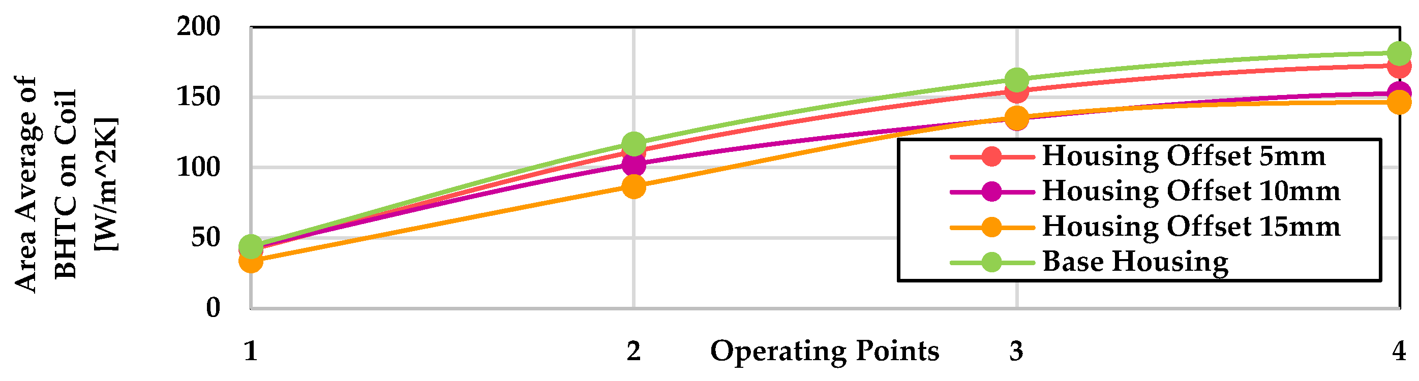
3.3. Cooling Capacity Case Study

Following the aforementioned methodology, a cooling capacity study was performed. This study evaluated four different housing geometries with case 1 being the base housing geometry, and cases 2, 3, and 4, where the housing diameter was offset by 5 mm, 10 mm, and 15 mm, respectively. A total of four operating points were evaluated, representing idle, 50%, rated, and maximum electric motor power [12]. A computation at each operating point showed that the mean bulk-flow-based heat transfer coefficient on the surface of the coils (windings) drops with increasing housing offset, therefore resulting in a decrease in cooling capacity (Figure 2).

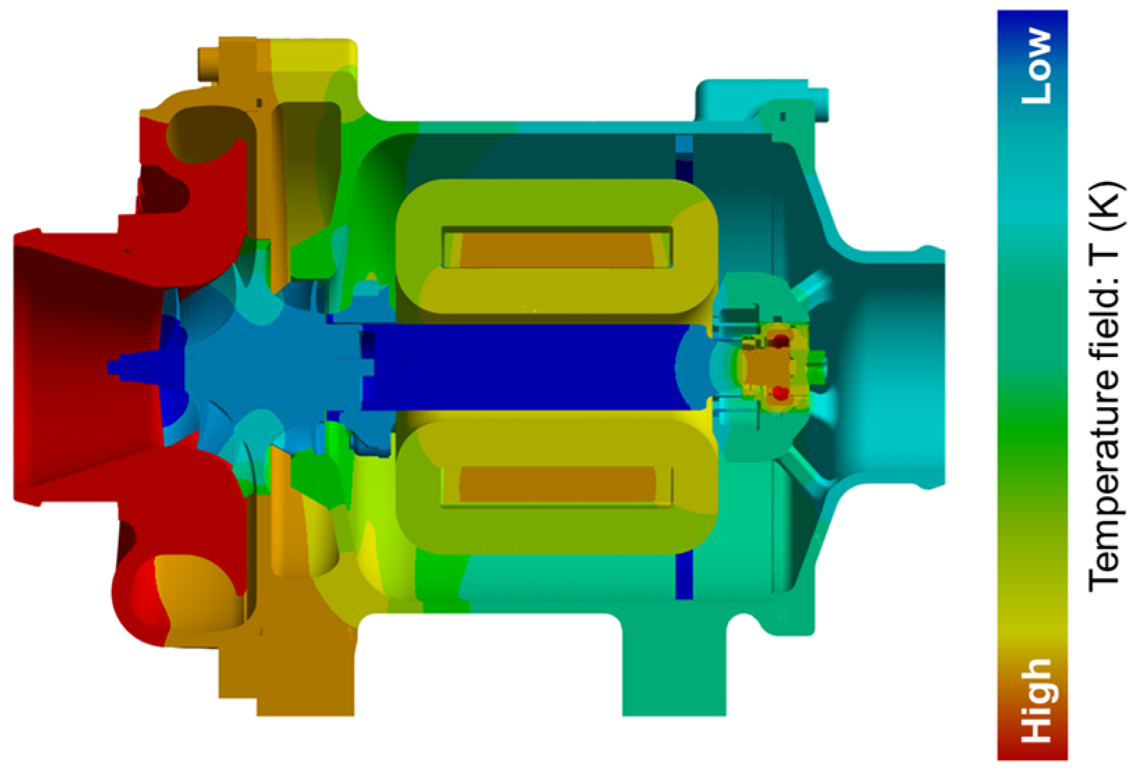
4. Solid Thermal Model

In order to evaluate the temperature field of the investigated machine, a steady state thermal model was created.

4.1. Model Setup

All solid material components were represented in the model, together with their material properties. Some of the main material properties specified in the model are density, thermal conductivity as a function of temperature, thermal capacity, etc. According to [26], the roughness (Rz) and contact pressure between two materials influence the coefficient of heat transfer in their contact area. Special care was given to the contact area between the coils and the stator. The windings were wrapped around the stator, creating a “torus” (toroidal winding). It was assumed that only 11% of the “ideal” contact area actually touches, leading to a heat transfer reduction factor of 0.11.
Thermal resistance calculation, between the coils and stator:
R s t a t o r , W i n d i n g s = 1 H T C i d e a l · 0.11 m 2 K W
Additionally, the copper wires were embedded in resin. The resin created a film thickness of 0.5 mm on average. This resin film influences the bulk-flow-based heat transfer coefficients in the winding surface. A new heat transfer coefficient was calculated in order to take this effect into account.
Total heat transfer coefficient on windings:
H T C t o t a l = 1 / T h i c k n e s s R e s i n   C o n d u c t i v i t y + 1 B H T C

4.2. Thermal Model Results

The created thermal model was used to calculate the temperature distribution at the maximum power operating point, expected to be the most demanding temperature-wise. The results are illustrated in Figure 3, featuring a cross-sectional view of the machine with the temperature field contour.
Key observations include a predicted maximum temperature of 164 degrees Celsius on the compressor side, while the rotor remains the coldest part of the machine at 31.8 degrees Celsius. The stator temperature ranges from 98 to 140 degrees Celsius, while the coils temperature varies from 86 to 99 degrees Celsius (Figure 3). These values are below the structural limit of 150 degrees Celsius, a temperature at which the resin starts delaminating and cracking, creating a risk of short-circuit. Information about the compressor inflow conditions considered in the aforementioned operating points can be found in [12]. The high-pressure ratios, particularly near maximum speed, justify the high compressor outlet temperatures.
Upon these findings, a prototype was built and tested. The first tests showed that it can operate within certain boundaries of the specified operating points, while an average of around 5 degrees Celsius higher measured temperature was found compared to that predicted at the housing, stator, and coils. Furthermore, it should be made clear that the working air used in the testbench was ambient air with no specific preconditioning of humidity, while a relative humidity of 90% is expected in fuel-cell operation. Humid air has better cooling properties due to the higher heat capacity and the heat necessary for the evaporation of droplets. The primary objective of this initial test was to verify whether the machine is functional. A detailed comparison of the presented results with the experimental results will be carried out in the near future, with the test environment being closely aligned to the operational boundary conditions also used in the methodology described.

5. Conclusions

The scope of this study was to create a methodology for the thermal evaluation of an electric turbocharger designated for hydrogen fuel-cell charging, while keeping the computational cost lower than a conjugate heat transfer model. This goal was achieved, as the methodology was successfully created for calculating the temperature distribution of the whole machine for the maximum power operating point. Furthermore, the calculation time was substantially smaller than a standard Conjugate Heat Transfer (CHT) analysis, assuming that the electromagnetic losses of the motor are given.

5.1. Electromagnetic Model

Looking individually at each model composing the methodology, two electromagnetic models were created, a two-dimensional and a three-dimensional one, aiming to accurately predict the electromagnetic losses that the operation of the electric motor creates. Both models found agreement in predicting negligible rotor losses, showcasing a beneficial characteristic of the chosen toroidal motor topology. However, the two-dimensional model could not capture the three-dimensional geometric features that influence the eddy–current creation and thus the losses, leading to an underestimation of the stator and housing losses and an overestimation of the output torque.

5.2. Computational Fluid Dynamics Model

In the CFD model, a mesh independence study was performed for the motor cavity, as there was no previous knowledge in simulating similar topologies. The Richardson extrapolation method was used successfully, and a “mesh independent” grid was retrieved. The bulk flow-based heat transfer coefficient method that is commonly used in the industry for temperature evaluation of a turbocharger was employed.
Using the “independent” mesh, a case study was performed where the effect of moving the housing away from the coils on the cooling capacity of the flow was investigated. It demonstrated that, as the housing-winding distance increases, the bulk flow-based heat transfer coefficients on the winding surface decrease. The drop of cooling capacity is counteracted by the decreasing induced losses on the housing while the housing is moved away from the coils. This creates a tradeoff that was investigated to find an optimal solution and led to the conclusion that the proposed and similar methods are of great importance to the design face of such machines.

5.3. Thermal Model

The thermal model predicted the temperature field and showed no worrying values in critical components. However, due to phase change during turbine expansion, the humid air at turbine inlet was not modeled. The temperature field might be underpredicted.
The coldest part of the machine was the rotor. Although the temperature reported was extremely low, some initial results coming from the tested prototype suggest that the rotor temperature is indeed the smallest in the current machine design. It is known that high-speed electric turbochargers have a problem achieving even higher speeds due to rotor temperatures that lead to magnet demagnetization. In the investigated machine, the toroidal slot-less design seems to overcome this problem, thus making it a promising candidate for high-speed electric turbochargers.

5.4. Virtual Proof of Concept

By using this methodology to simulate the most demanding operating point of the machine, regarding temperature and power, it was shown that the estimated temperature values are lower than the critical values, offering, thus, a successful verification for the toroidal motor integration and the novel cooling concept.

Author Contributions

Conceptualization, M.R., R.D., G.S.A. and R.B.; methodology, G.S.A. and R.D.; software, G.S.A.; validation, G.S.A., R.D., M.R. and R.B.; resources, IHI-CSI; writing—original draft preparation, G.S.A.; writing—review and editing, G.S.A., G.I. and R.D.; visualization, G.S.A.; supervision, R.D., G.I. and A.I.K.; project administration, M.R. All authors have read and agreed to the published version of the manuscript.

Funding

The authors are grateful for the financial support under the research grant 19/21046A provided by the Federal Ministry for Economic Affairs and Climate Action on the basis of a decision by the German Bundestag. The authors are responsible for the content of this publication.

Institutional Review Board Statement

Not applicable.

Informed Consent Statement

Not applicable.

Data Availability Statement

The data presented in this study are available on request from the corresponding author (due to privacy restrictions) with the permission of IHI Charging Systems International.

Conflicts of Interest

Authors Georgios Iosifidis, Roberto DeSantis and Martin Rode were employed by the company IHI Charging Systems International GmbH. Author Raphael Burgmair was employed by the company Silver Atena GmbH. The remaining authors declare that the research was conducted in the absence of any commercial or financial relationships that could be construed as a potential conflict of interest.

References

  1. ICCT. The International Council on Clean Transportation. Available online: https://theicct.org/transport-could-burn-up-the-eus-entire-carbon-budget/ (accessed on 23 April 2023).
  2. United Nations Climate Change. Available online: https://unfccc.int/process-and-meetings/the-paris-agreement (accessed on 12 April 2023).
  3. European Commission. Available online: https://energy.ec.europa.eu/topics/energy-systems-integration/hydrogen/key-actions-eu-hydrogen-strategy_en (accessed on 12 April 2023).
  4. IRENA. Available online: https://www.irena.org/Energy-Transition/Outlook (accessed on 23 April 2022).
  5. Yan, Q.; Toghiani, H.; Causey, H. Steady state and dynamic performance of proton exchange membrane fuel cells (PEMFCs) under various operating conditions and load changes. J. Power Sources 2006, 161, 492–502. [Google Scholar] [CrossRef]
  6. Schmelcher, M.; Häßy, J. Hydrogen fuel cells for aviation? A potential analysis comparing different thrust categories. In Proceedings of the ISABE 2022, Ottawa, ON, Canada, 25–30 September 2022. [Google Scholar]
  7. Clean Hydrogen Partnership. Hydrogen-Powered Aviation—European Commission. Available online: https://european-union.europa.eu/index_el (accessed on 11 April 2023).
  8. Filsinger, D.; Kuwata, G.; Ikeya, N. Tailored Centrifugal Turbomachinery for Electric Fuel Cell Turbocharger. Int. J. Rotating Mach. 2021, 2021, 3972387. [Google Scholar] [CrossRef]
  9. Garrett Advancing Motion. Available online: https://www.garrettmotion.com/emission-reduction/garrett-e-turbo/ (accessed on 4 May 2023).
  10. Spinner, G.; Dahinten, F.; Dauscher, S.; Münz, S. Electrified boosting systems in today’s and future automotive applications. In Proceedings of the 2018 Thirteenth International Conference on Ecological Vehicles and Renewable Energies (EVER), Monte Carlo, Monaco, 10–12 April 2018; pp. 1–5. [Google Scholar] [CrossRef]
  11. Blunier, B.; Miraui, A. Proton Exchange Membrane Fuel Cell air Management in Automotive Applications. J. Electrochem. Energy Convers. Storage 2010, 7, 041007. [Google Scholar] [CrossRef]
  12. Rathke, P.; Di Modica, D.V.; Fink, S.K.; Filsinger, D.; Burgmair, R.; von Unwerth, T. Model Based Investigation on Drive Train Performance of a Heavy-Duty Fuel Cell Truck Focusing on the Fuel Cell Air Delivery System. In Proceedings of the FC3 Fuel Cell Conference, Chemnitz, Germany, 12–13 November 2024. [Google Scholar]
  13. Hayashi, K.; Kaneda, S.; Ikeya, N.; Daito, Y.; Kitamura, K. Development of Electric Turbocharger for Fuel Cell Systems to Contribute to the Realization of Carbon Neutrality. IHI Eng. Rev. 2023, 56. Available online: https://www.ihi.co.jp/en/technology/techinfo/contents_no/1199411_13586.html (accessed on 13 March 2025).
  14. Gilson, A.; Dubas, F.; Depernet, D.; Espanet, C. Comparison of high-speed PM machine topologies for electrically-assisted turbocharger applications. In Proceedings of the 2016 19th International Conference on Electrical Machines and Systems (ICEMS), Chiba, Japan, 13–16 November 2016; pp. 1–5. [Google Scholar]
  15. Xu, F. Investigation of High-Speed Permanent Magnet Motors with Toroidal Windings. Ph.D. Thesis, University of Sheffield, Sheffield, UK, 2022. [Google Scholar]
  16. Tavernier, S.; Espanet, C.; Andrieux, G. Modeling and Optimal Design of a Very High Speed Motor Slotless Technology with Toroidal Winding for Serial Production. In Proceedings of the 2021 IEEE Energy Conversion Congress and Exposition (ECCE), Vancouver, BC, Canada, 10–14 October 2021. [Google Scholar]
  17. Borisavljevic, A.; Jumayev, S.; Lomonova, E. Toroidally-wound permanent magnet machines in high-speed applications. In Proceedings of the 2014 International Conference on Electrical Machines (ICEM), Berlin, Germany, 2–5 September 2014. [Google Scholar]
  18. Suzuki, M.; Sakai, K. Reduction of torque ripple for PM motor with toroidal winding. In Proceedings of the 2016 19th International Conference on Electrical Machines and Systems (ICEMS), Chiba, Japan, 13–16 November 2016. [Google Scholar]
  19. Karamavruc, A. Obtaining bulk flow based heat transfer coefficients for thermal evaluation of turbochargers. In Proceedings of the IMechE Conference, London, UK, 17–18 May 2016; BorgWarner Global Core Science-Structural Mechanics: Arden, NC, USA, 2016. [Google Scholar]
  20. Adrian, M.; Marian, L.; Mariusz, K. Influence of an end-winding size on proximity losses in a high-speed PM synchronous motor. In Proceedings of the 2015 Selected Problems of Electrical Engineering and Electronics (WZEE), Kielce, Poland, 17–19 September 2015. [Google Scholar]
  21. Harley, P.; Spence, S.; Filsinger, D.; Dietrich, M.; Early, J. Experimental and numerical benchmarking of an improved meanline modeling method for automotive turbocharger centrifugal compressors. In Proceedings of the ASME Turbo Expo 2015, Montreal, QC, Canada, 15–19 June 2015. [Google Scholar]
  22. Tsilingiris, P. Thermophysical and transport properties of humid air at temperature range between 0 and 100 °C. Energy Convers. Manag. 2007, 49, 1098–1110. [Google Scholar] [CrossRef]
  23. Celik, I.B.; Ghia, U.; Roache, P.J.; Freitas, C.J. Procedure for Estimation and Reporting of Uncertainty. ASME J. Fluids Eng. 1993, 115, 194–195. [Google Scholar] [CrossRef]
  24. Slater, J.W. Examining Spatial (Grid) Convergence; NASA: Washington, DC, USA, 2021.
  25. Kader, B.A. Temperature and concentration profiles in fully turbulent boundary layers. Int. J. Heat Mass Transf. 1981, 24, 1541–1544. [Google Scholar] [CrossRef]
  26. Alexandrovic, U.V.; Reinhold, K.; Jovan, M. Experimental Investigation and Modeling of Contact Heat Transfer. Doctoral Dissertation, RWTH Aachen University, Aechen, Germany, 2018. [Google Scholar]
Figure 1. 3D electromagnetic analysis computational domain: (a) Part of the computational domain depicting the non-meshed coils wrapped around the stator; (b) Stator magnetic flux distribution at maximum power operating point.
Engproc 90 00048 g001
Figure 2. Bulk flow-based heat transfer coefficients average value on the surface of the windings plotted against operating points evaluated for all cases investigated.
Engproc 90 00048 g002
Figure 3. Temperature field of the Electric Turbocharger at maximum power operating point.
Engproc 90 00048 g003
Disclaimer/Publisher’s Note: The statements, opinions and data contained in all publications are solely those of the individual author(s) and contributor(s) and not of MDPI and/or the editor(s). MDPI and/or the editor(s) disclaim responsibility for any injury to people or property resulting from any ideas, methods, instructions or products referred to in the content.

