Proceeding Paper

Development of a Heat Transfer Model for a Free Double Piston and Identification of Thermal Management Challenges †

by
Konstantinos Fotis
1,2,*,
Zinon Vlahostergios
1,2,
Dimitrios Misirlis
2,3 and
Kyros Yakinthos
2
1
Laboratory of Fluid Mechanics and Hydrodynamic Machines, Department of Production and Management Engineering, Democritus University of Thrace, 67100 Xanthi, Greece
2
Laboratory of Fluid Mechanics and Turbomachinery, Department of Mechanical Engineering, Aristotle University of Thessaloniki, 54124 Thessaloniki, Greece
3
Department of Mechanical Engineering, International Hellenic University, 62124 Serres, Greece
*
Author to whom correspondence should be addressed.
Presented at the 14th EASN International Conference on “Innovation in Aviation & Space towards sustainability today & tomorrow”, Thessaloniki, Greece, 8–11 October 2024.
Eng. Proc. 2025, 90(1), 45; https://doi.org/10.3390/engproc2025090045
Published: 14 March 2025

Abstract

The Free Double-Piston Composite Cycle Engine (FDP-CCE) integrates the turbofan engine architecture with the characteristics of piston engines with the aim of improving engine efficiency and decreasing CO2 emissions. The FDP-CCE features a free-piston design, providing a lighter and more compact structure compared to conventional crankshaft-connected piston engines due to the elimination of mechanical transmissions and lubrication systems. Innovations like air lubrication and increased piston velocities contribute to higher cylinder temperatures, underscoring the need for advanced thermal management strategies. For this reason, in the present work, a heat transfer model to address the thermal management challenges in this innovative engine design is developed. More specifically, a novel filling–discharge model for a two-stroke compression ignition engine is developed, dividing the operational cycle into phases handled by the piston engine and the piston compressor. Special emphasis is given to the implementation of various geometric zones for each piston to optimize the heat transfer between the combustion chamber and the cylinder walls and heads. The final step of this research work involves the integration of piston temperatures into the boundary conditions of an equivalent computational domain to conduct a detailed heat transfer and fluid flow analysis around and on the FDP cylinder. By focusing on these critical aspects, this study establishes a fundamental framework for future aeroengine designs, promoting sustainable propulsion solutions with reduced fuel consumption and emissions.

1. Introduction

The aviation industry continuously seeks to enhance engine efficiency and to reduce the carbon emissions due to growing environmental concerns and the stricter regulatory frameworks [1]. Traditional aeroengine designs, particularly turbofans, are approaching their theoretical performance limits [2]. As a result, alternative propulsion concepts, such as the Free Double-Piston Composite Cycle Engine (FDP-CCE), depicted in Figure 1a, have gained significant interest due to their potential to combine the best features of piston engines with the architecture of turbofans [3]. By integrating these two systems, the FDP-CCE promises higher efficiency and lower emissions, making it a strong candidate for next-generation aviation propulsion technologies. The FDP-CCE leverages a free-piston design, as illustrated in Figure 1b, which eliminates the need for mechanical transmissions such as crankshafts and lubrication systems, reducing engine weight and complexity [4]. Additionally, this configuration allows for increased piston velocities and more compact engine structures, offering a significant improvement in engine performance [5]. However, these innovations also introduce unique challenges, particularly in thermal management. The higher piston velocities, coupled with innovations like air lubrication [6], result in significantly elevated temperatures within the engine combustion chambers and cylinder walls, requiring new approaches to thermal management. Effective thermal management is crucial for maintaining engine performance, reliability, and longevity [7]. In high-temperature environments, the durability of engine materials can deteriorate, and inefficient heat dissipation strategies may lead to overheating. Therefore, developing an accurate and comprehensive heat transfer model for the FDP-CCE is essential to address these thermal challenges and ensure the engine’s safe and efficient operation.
As detailed in previous work [8], a novel heat transfer model tailored for the FDP was utilized to address thermal management challenges. Specifically, a filling–discharge model for a two-stroke compression ignition engine was introduced, dividing the operational cycle into phases handled by both the piston engine and the piston compressor. Special attention was given to optimizing heat transfer within the combustion chamber and cylinder by implementing various geometric zones. These zones were carefully designed to enhance the heat transfer between the combustion gases, cylinder walls, and heads, ensuring that thermal loads are evenly distributed.
The scope of this paper is the integration of the heat transfer model at the boundaries of the computational domain, including the implementation of heat flux with a User-Defined Function (UDF) to investigate external heat transfer [11].

2. Methodology

The primary objective of this study is to develop a computational model for the two-stroke Free Double-Piston (FDP) cylinder to investigate external heat transfer. This section outlines the computational domain setup and examines three key parameters aimed at enhancing the cooling efficiency of the FDP system:
Bypass Heat Transfer Coefficient: A range of 50 to 300 W/m2K is employed to optimize convective cooling performance. This range is based on theoretical calculations for air flowing over cylindrical geometries at high velocities.
Material Selection: The properties of the cylinder and surrounding regions are evaluated to determine their influence on thermal behavior.
Heat Dissipation Analysis: The study also focuses on analyzing and quantifying the amount of heat dissipated from the system, providing insights into overall thermal management.

2.1. Computational Domain Setup
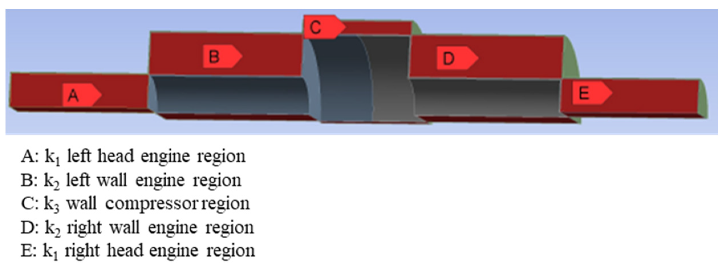
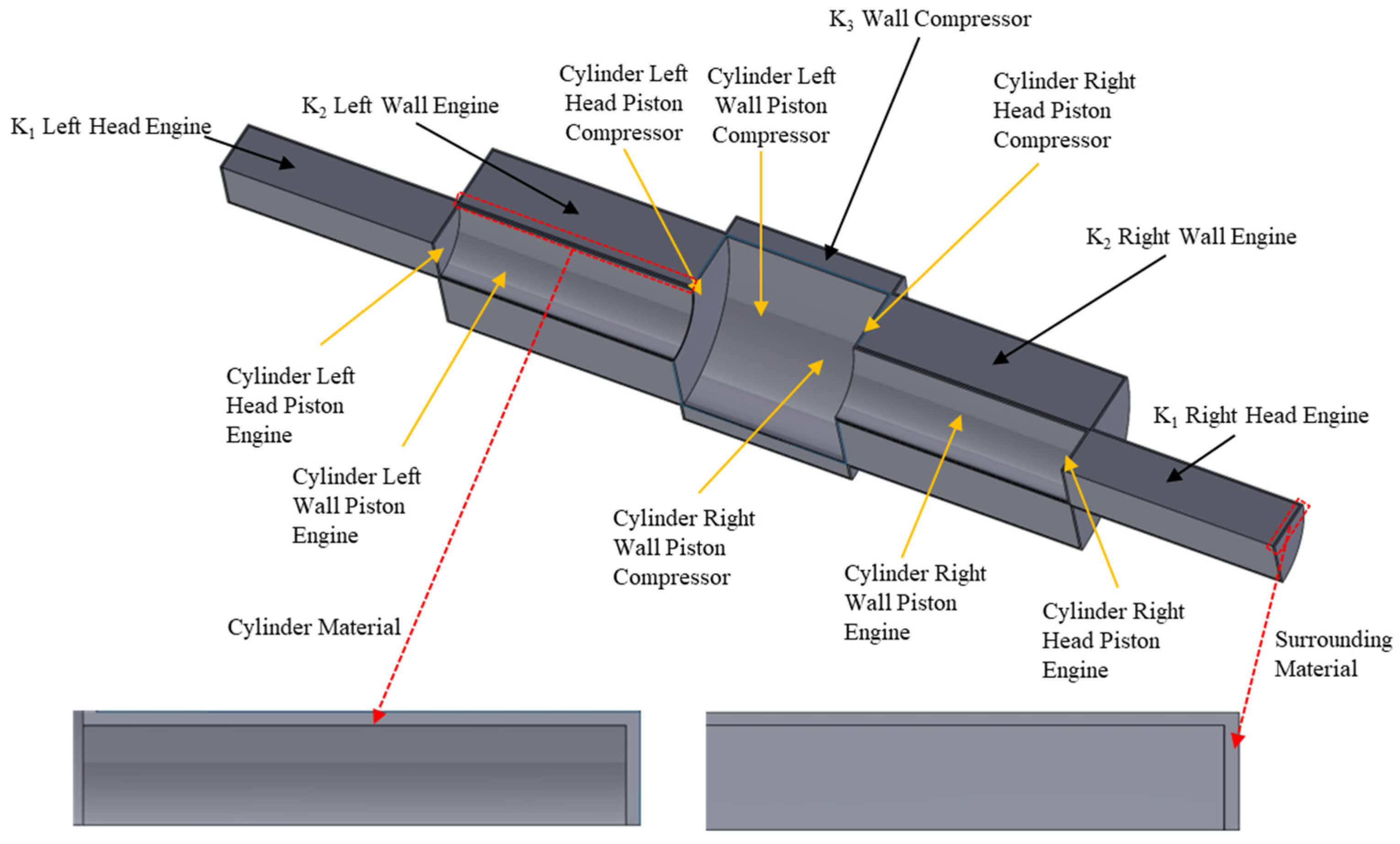
This section provides a detailed description of the setup process for the computational domain used in simulating the two-stroke Free Double-Piston (FDP) cylinder engine. The setup includes the geometry, mesh generation, boundary conditions, and modeling parameters.

2.1.1. Geometry

The geometric model of the two-stroke Free Double-Piston (FDP) cylinder engine, as illustrated in Figure 2, consists of two pistons: the piston compressor and the piston engine. The yellow arrows in the Figure indicate the key geometric components of the FDP. The black arrows highlight the surrounding regions, which will be further described during the explanation of the cooling methodology. The red regions represent the materials of the cylinders and the surrounding region. Some assumptions and simplifications were made to facilitate the computational modeling process. Due to the symmetry of the system, only one-quarter of the cylinder was modeled. This symmetry reduction minimizes the computational cost while the accuracy of the results is maintained.

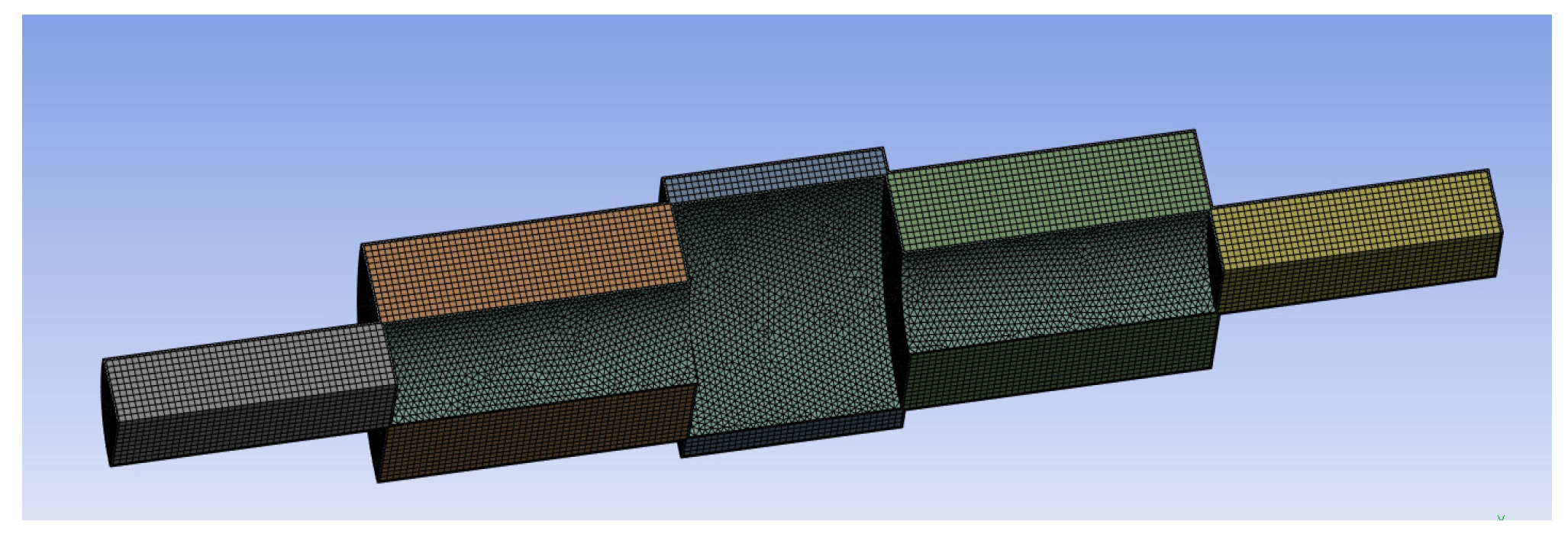
2.1.2. Mesh Generation

In Figure 3, a uniform grid size of 2 × 10⁻³ m was applied to discretize the geometry, resulting in a computational domain with approximately 1.34 million elements.

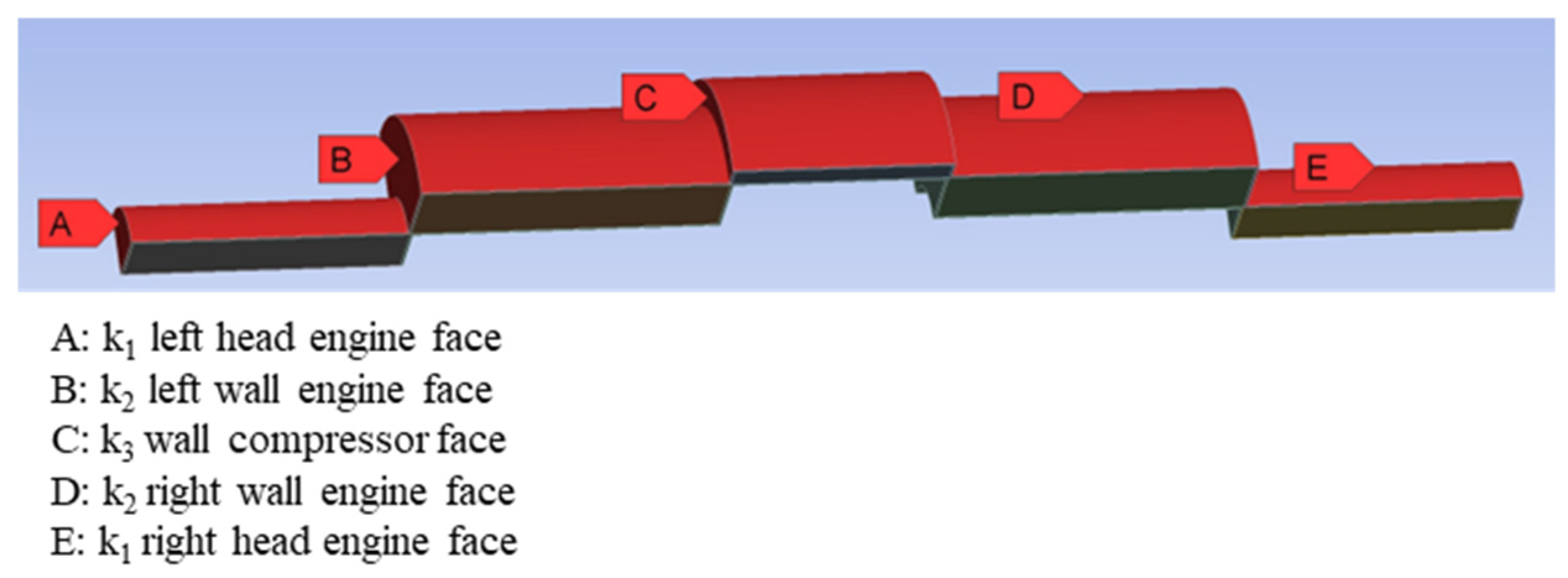
2.1.3. Boundary Conditions

For all the components of the free double piston, including the cylinders walls and heads of both pistons, the heat flux boundary conditions have been integrated using a User-Defined Function (UDF), which is customized for the two-stroke Free Double-Piston (FDP) model.

2.1.4. Computational Setup

The primary computational setup parameters, including the grid size and the boundary conditions for both pistons, are summarized in Table 1.

2.2. Strategy for Using Bypass Air for Cooling

The methodology developed for investigating the use of bypass air in cooling of the two-stroke Free Double-Piston (FDP) engine focuses on a systematic approach to understanding and improving the cooling efficiency through three key steps:
Enhancement of Convective Cooling via Bypass Transfer Coefficient
Analysis and Quantification of Heat Dissipation
Evaluation of Cylinder and Surrounding Materials

2.2.1. Enhancement of Convective Cooling via Bypass Transfer Coefficient

The first phase of the methodology focuses on improving the convective cooling by adjusting the bypass heat transfer coefficient, which ranges from 0 to 300 W/m2K, as shown in Table 2. The bypass air flows through the surrounding region, aiding in heat removal from the free double piston, as illustrated in Figure 4.
The Figure highlights with the red color the areas where the bypass heat transfer coefficients are applied, corresponding to the faces depicted in the temperature distribution results in Section 3.1.

2.2.2. Analysis and Quantification of Heat Dissipation

The second phase of this study involves the analysis and the quantification of the total heat dissipation from the system, focusing on how efficiently the bypass air cools the free double piston. Additionally, the results from this phase will be compared with those from the first phase to assess improvements in cooling performance.
Figure 5 illustrates the key regions of the engine where heat dissipation is calculated. The heat dissipation, q d i s s i p a t i o n , is evaluated using the following Equation:
q d i s s i p a t i o n = h b y p a s s T w T b y p a s s ,
where:
h b y p a s s represents the bypass heat transfer coefficient, ranging from 50 to 300 W/m2K, as shown in Table 3;
T w is the wall temperature of each piston cylinder block;
T b y p a s s represents the temperature of the bypass air.
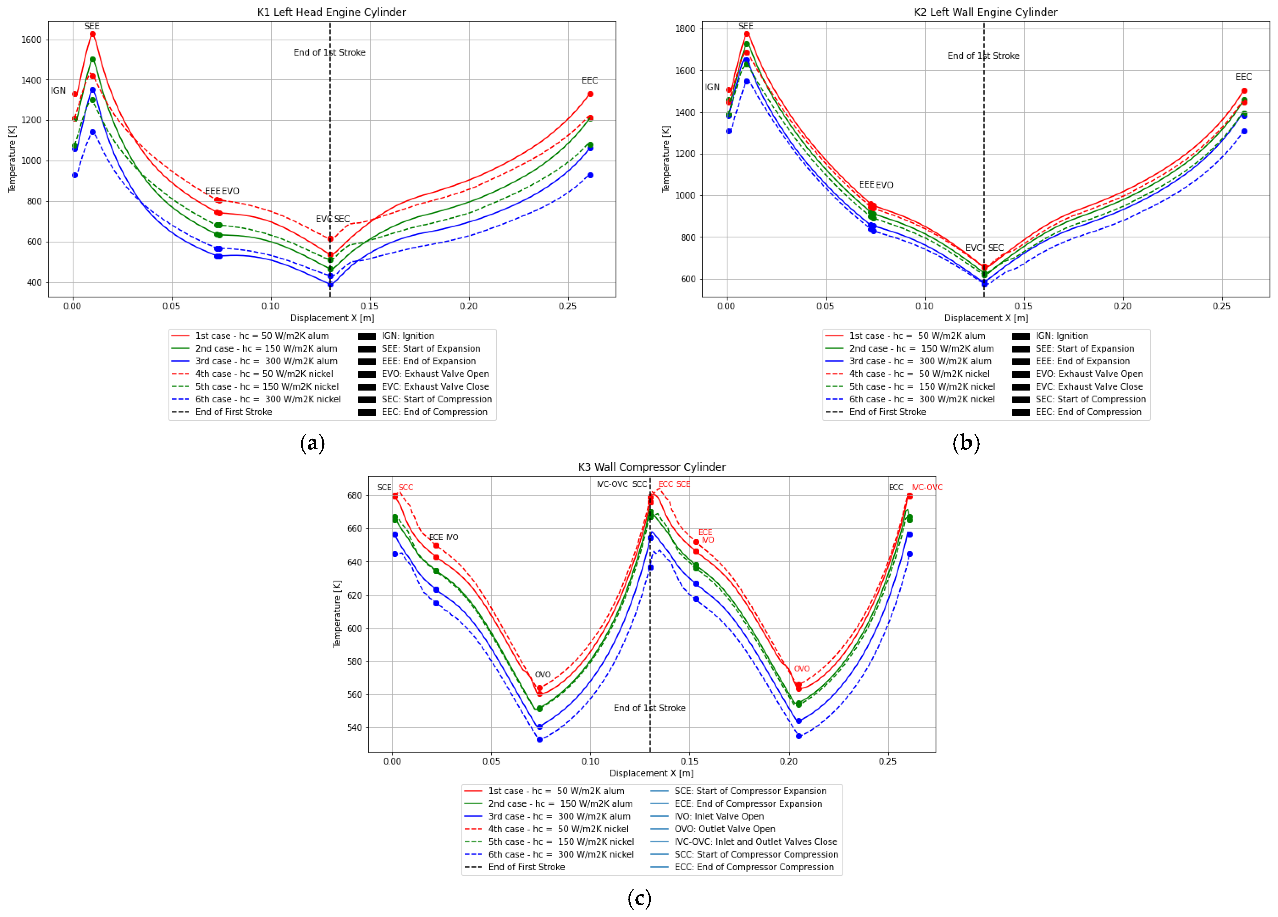
Figure 5. Key regions of the FDP engine where the heat flux dissipation strategy is applied.
Engproc 90 00045 g005
Table 3. Computational model cases with variations in bypass heat transfer coefficient for heat flux dissipation.
1st Case2nd Case3rd Case4th Case5th Case6th Case
Cylinder MaterialAluminum alloyAluminum alloyAluminum alloyNickel alloyNickel alloyNickel alloy
Surrounding MaterialAluminum alloyAluminum alloyAluminum alloyAluminum alloyAluminum alloyAluminum alloy
Bypass Hc50 W/m2K150 W/m2K300 W/m2K50 W/m2K150 W/m2K300 W/m2K
This equation is applied to calculate the heat flux (W/m2) across each surface block in the surrounding region. The labeled blocks A to E in the Figure represent critical areas of the engine where the heat dissipation is calculated. The analysis follows these key steps:
The heat flux, q d i s s i p a t i o n , is calculated for each block in the surrounding region to determine the amount of heat being removed from the engine components by the bypass air.
The temperature difference between the wall temperature ( T w ) and the bypass air temperature ( T b y p a s s ) is a key parameter in calculating the rate of heat dissipation.
After calculating the heat flux for each surface block, the heat dissipation per unit volume (W/m3) is computed for the corresponding blocks. This step provides a detailed quantification of the heat removed relative to each block’s volume.
The calculated heat dissipation is integrated into the overall computational domain using a User-Defined Function (UDF).
The temperature distribution results across the faces depicted in Figure 4 are evaluated, as presented in Section 3.2.

2.2.3. Evaluation of Cylinder and Surrounding Materials

The final phase of the two studies evaluates the thermal properties and performance of different materials used in the cylinder and the surrounding regions. This evaluation aims to determine the optimal material combination to enhance heat transfer and improve the overall cooling performance. For the surrounding region, the aluminum alloy was selected due to its lightweight properties and its high thermal conductivity. Aluminum alloy is ideal for efficient heat dissipation, ensuring heat removal from the system and maintaining lower operating temperatures. Two materials were evaluated for the cylinder: aluminum alloy and nickel-based alloy. The nickel-based alloy was chosen due to its low thermal conductivity, which reduces heat dissipation, and its ability to withstand higher temperatures than aluminum alloy.

3. Results and Discussion

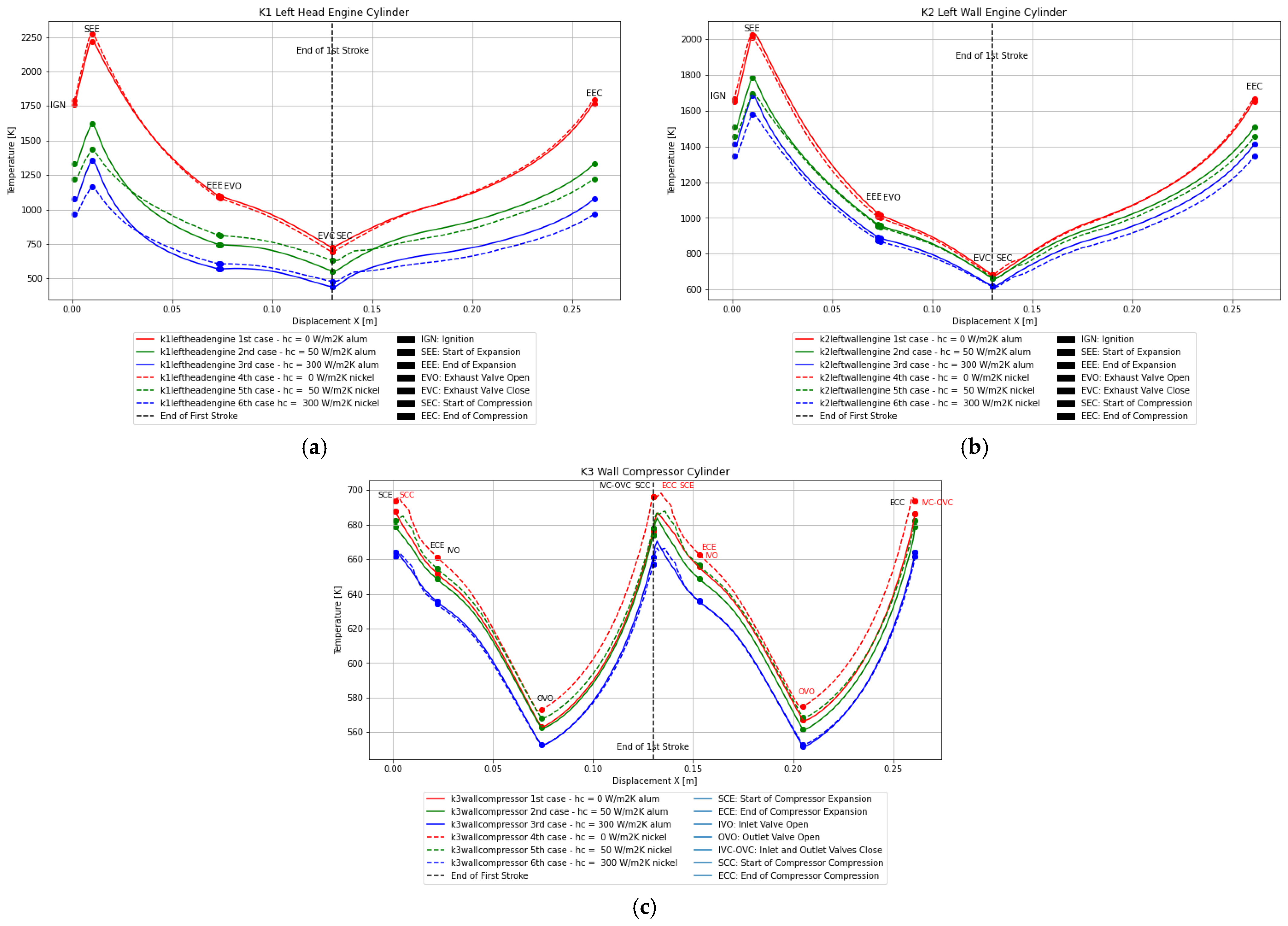
3.1. Results of Enhancement of Convective Cooling via Bypass Heat Transfer Coefficient

Figure 6 illustrates the impact of different bypass heat transfer coefficients (0, 50, and 300 W/m2K) on the temperature distribution across different faces in Figure 4 of the FDP engine during a complete operating cycle, as detailed in [9]. The end of first stroke is indicated by the black dashed line. Additionally, the Figures compare the thermal behavior of aluminum alloy and nickel-based alloy cylinders, highlighting the influence of material selection on heat dissipation and the overall thermal management. The dashed and solid lines represent temperature profiles for specific areas of the FDP engine, corresponding to nickel and aluminum as the cylinder material, respectively. As the bypass heat transfer coefficient increases from 0 to 300 W/m2K, a consistent decrease in temperature is observed. In the K2-left-wall engine cylinder, the peak temperature occurs during the completion of the combustion phase and the beginning of the expansion phase (SEE) within the engine piston. This region shows a significant reduction as the bypass heat transfer coefficients increase. For aluminum at 50 W/m2K, the peak temperature decreases to 1784 K—a 12.1% reduction compared to 0 W/m2K—and for nickel under the same conditions, it reduces to 1693 K, representing a 16.6% reduction. At 300 W/m2K, the aluminum temperature decreases further to 1686 K (a 16.8% reduction), while nickel reduces it to 1578 K (a 22.2% reduction). Similarly, in the K1-left-head engine cylinder, the temperature for aluminum at 50 W/m2K drops to 1620 K, marking a 26.8% reduction, and for nickel, it decreases to 1433 K, corresponding to a 35.3% reduction. At 300 W/m2K, the aluminum temperature drops to 1358 K (a 38.7% reduction), while nickel achieves a greater reduction to 1166 K, representing a 47.3% decrease.
In contrast, the K3-wall compressor cylinder shows a different behavior due to its lower thermal loads. This region surrounds both the left- and right-wall piston compressors, with the black symbols indicating the left wall’s procedure, and the red symbols illustrating the right wall’s procedure. The peak temperature for aluminum with a bypass heat transfer coefficient of 0 W/m2K is 688 K. At 50 W/m2K, the temperature slightly reduces to 683 K (a 0.63% reduction), while nickel shows a negligible decrease to 687 K (a 0.05% reduction). At 300 W/m2K, the temperature drops to 670 K for aluminum (a 2.6% reduction) and to 666 K for nickel (a 3.2% reduction).

3.2. Results of the Analysis and Quantification of Heat Dissipation

In Figure 7, the results illustrate the effectiveness of the heat dissipation strategy across each block of the surrounding region of the free double-piston engine, as described in Section 2.2.2. The key variables examined include the heat flux from heat dissipation (calculated using Equation (1)) and the material selection for the cylinder, comparing the aluminum and the nickel-based alloys. The graphs use dashed lines to represent the temperature profiles for nickel as the cylinder material and solid lines for aluminum alloys, corresponding to the regions shown in Figure 4. As heat dissipation increases with rising bypass heat transfer coefficients from 50 to 300 W/m2K, the temperature profiles across all regions decrease. Cases using a nickel-based alloy as the cylinder material achieve slightly lower temperatures compared to aluminum, particularly at higher bypass heat transfer coefficients.
For instance, in the K2-left-wall engine cylinder, with aluminum as the material both the cylinder and the surrounding region, the peak temperature is 2030 K at 0 W/m2K, as shown in Figure 6. At 50 W/m2K, the peak temperature drops to 1776 K (a 12.5% reduction) and to 1686 K for nickel under the same conditions (a 16.9% reduction). At 300 W/m2K, the peak temperature with aluminum further decreases to 1658 K (a 18.3% reduction), while the use of nickel as the cylinder material reduces the peak temperature to 1548 K (a 23.7% reduction).
Similarly, in the K1-left-head engine cylinder, the peak temperature is 2216 K at 0 W/m2K. With aluminum at 50 W/m2K, the temperature drops to 1627 K (a 26.5% reduction), while for nickel at the same bypass heat transfer coefficient, it reduces to 1432 K (a 35.3% reduction). At 300 W/m2K, the case with the use of aluminum as the cylinder material, the temperature decreases to 1353 K (a 38.9% reduction), and with nickel, it drops further to 1143 K (a 48.3% decrease).
Conversely, as shown in Figure 7, the K3-wall compressor cylinder encompasses both the left- and the right-wall piston compressors, as previously explained. The black symbols represent the operations for the left wall while the red symbols correspond to the operations for the right wall. For aluminum as the cylinder material with a bypass heat transfer coefficient of 0 W/m2K, the peak temperature reaches 688 K. As the heat flux dissipation increases, using aluminum as the cylinder material with a bypass heat transfer coefficient of 50 W/m2K, the temperature reduces to 680 K, representing a 1.10% reduction. In comparison, using nickel as the cylinder material shows a slight temperature reduction to 684 K, corresponding to a 0.6% decrease. When the bypass heat transfer coefficient is further increased to 300 W/m2K, the temperature drops to 657 K for aluminum (a 4.4% decrease) and to 646 K for nickel (a 6.0% reduction).

4. Conclusions

This study analyzed the thermal management of a two-stroke Free Double-Piston (FDP) engine by examining the effects of different bypass heat transfer coefficients, the heat flux dissipation, and the material selection of the free double-piston cylinders. During the first study, the results demonstrate that the heat transfer coefficient plays a critical role in reducing peak temperatures in high thermal load areas, such as the engine walls and heads. Increasing the heat transfer coefficient from 50 W/m2K to 300 W/m2K significantly enhances convective cooling, achieving peak temperature reductions of up to 47.3% in K1-left-head engine cylinder. Nickel-based alloys present slightly better results than aluminum in terms of temperature reduction at the faces of the surrounding region, particularly at higher heat transfer coefficients, due to their lower thermal conductivity. For instance, at a bypass heat transfer coefficient of 300 W/m2K, nickel alloys achieve a temperature reduction of 23.7% in the K2-left-wall engine cylinder and 47.3% in the K1-left-head engine cylinder compared to the case without bypass cooling (0 W/m2K). Conversely, regions with lower thermal loads, such as the K3-wall compressor cylinder, showed negligible dependence on the variations in the bypass heat transfer coefficient, with a maximum temperature reduction of 6.0% for nickel at 300 W/m2K.
The second study focused on the analysis and quantification of heat dissipation using a more detailed approach. The results highlight the slightly superior performance of nickel-based alloys as the cylinder material for heat management, particularly in high-temperature regions of the engine, such as those following the combustion and compression phases, where the piston engine reaches its peak temperature. This finding is evident from the graphs, which show that the surrounding regions achieve slightly greater temperature reduction when using nickel compared to aluminum as the cylinder material. In contrast with the first study, where the temperature was calculated at the surrounding faces by varying the heat transfer coefficient, the second study provided a more detailed approach. In this case, the heat flux dissipation was calculated using Equation (1), which determined the temperature of each piston cylinder at each x-displacement, assuming the bypass air was 300 K. Despite the differences in approach, the results in Section 3.1 and Section 3.2 indicate that the differences between the two strategies are minimal.
In conclusion, the study emphasizes the importance of both material selection and heat transfer coefficient in optimizing the thermal performance of FDP engines. The results indicate that the selection of materials and cooling strategies can improve the thermal management of FDP engines, particularly in high-temperature regions. Future research could investigate alternative cooling methods or advanced materials to further improve heat dissipation and thermal management in FDP engines, expanding the potential applications of this engine technology.

Author Contributions

Conceptualization, Z.V., D.M. and K.Y.; methodology, Z.V. and D.M.; software, K.F.; validation, K.F. and K.Y.; formal analysis, K.F. and K.Y.; writing—original draft preparation, K.F.; writing—review and editing, ALL; visualization, K.F.; supervision, Z.V.; project administration, K.Y.; funding acquisition, ALL. All authors have read and agreed to the published version of the manuscript.

Funding

This research of the MINIMAL project was funded by the European Union’s Horizon Europe research and innovation programme under grant agreement No: 101056863.

Institutional Review Board Statement

Not applicable.

Informed Consent Statement

Not applicable.

Data Availability Statement

Data are contained within the article.

Acknowledgments

The research is part of the “Minimal environmental impact ultra-efficient cores for aircraft propulsion”—MINIMAL project funded by the European Union’s Horizon Europe research and innovation program under grant agreement no. 101056863.

Conflicts of Interest

The authors declare no conflict of interest.

References

  1. Jensen, L. Revision of the EU Emissions Trading System: Aviation; European Parliament: Strasbourg, France, 2022. [Google Scholar]
  2. Epstein, A.H. Aeropropulsion for Commercial Aviation in the Twenty-First Century and Research Directions Needed. AIAA J. 2014, 52, 901–911. [Google Scholar] [CrossRef]
  3. Zima, S. Ungewöhnliche Motoren, 1st ed.; Vogel Communications Group GmbH & Co. KG: Würzburg, Germany, 2004. [Google Scholar]
  4. Klingels, H. Wärmekraftmaschine mit Freikolbenverdichter. DE Patent 10 2012 206 123 A1, 17 October 2013. [Google Scholar]
  5. Achten, P.; van den Oever, J.; Potma, J.; Vael, G. Horsepower with Brains: The Design of the CHIRON Free Piston Engine; SAE Technical Paper 2000-01-2545; Society of Automotive Engineers (SAE): Warrendale, PA, USA, 2000. [Google Scholar] [CrossRef]
  6. Khaimovich, M. Hydraulic Control of Machine Tools, 1st ed.; Oxford Pergamon Press: Oxford, UK, 1965. [Google Scholar]
  7. Jafari, S.; Nikolaidis, T. Thermal Management Systems for Civil Aircraft Engines: Review, Challenges and Exploring the Future. Appl. Sci. 2018, 8, 2044. [Google Scholar] [CrossRef]
  8. MTU Engines. Blazing New Trails: MTU Aero Engines Showcases Innovative Evolutionary and Revolutionary Technologies for Commercial Aircraft at the 2019 Paris Air Show. Available online: www.mtu.de/fileadmin/EN/7_News_Media/1_Press/1_Latest_Press_Realeases/2019/Composite_Cycle.en.jpg (accessed on 12 August 2024).
  9. Fotis, K.C.; Vlahostergios, Z.; Misirlis, D.; Yakinthos, K. Heat transfer model development for the Free Double Piston engine concept, In Proceedings of the Technical Conference for Power and Propulsion Sector (GPPS Chania24), Chania, Greece, 4–6 September 2024. [CrossRef]
  10. Kaiser, S.; Schmitz, O.; Klingels, H. Aero Engine Concepts Beyond 2030: Part 2—The Free-Piston Composite Cycle Engine. ASME J. Eng. Gas Turbines Power 2021, 143, 021002. [Google Scholar] [CrossRef]
  11. ANSYS, Inc. ANSYS Fluent 12.0 User’s Guide; ANSYS, Inc.: Canonsburg, PA, USA, 2009. [Google Scholar]
Figure 1. (a) Composite Cycle Engine [8]; (b) Free Double Piston [9,10].
Engproc 90 00045 g001
Figure 2. Computational Domain.
Engproc 90 00045 g002
Figure 3. Computational grid of the thermal management area around the piston.
Engproc 90 00045 g003
Figure 4. Key faces of the FDP engine where the bypass heat transfer coefficient varies.
Engproc 90 00045 g004
Figure 6. Temperature profiles as a function of piston displacement for various heat transfer coefficients and materials. (a) K1-left-head engine cylinder; (b) K2-left-wall engine cylinder; (c) K3-wall compressor cylinder.
Engproc 90 00045 g006
Figure 7. Temperature profiles as a function of piston displacement for various heat transfer coefficients and materials in the heat dissipation analysis. (a) K1-left-head engine cylinder; (b) K2-left-wall engine cylinder; (c) K3-wall compressor cylinder region.
Engproc 90 00045 g007
Table 1. Computational Setup and Mesh Grid Size.
ParameterValue/Description
Piston Wall FluxUDF (defined from 2-stroke FDP model)
Element Size2 × 10−3 m
Number of Elements1.34 million
Table 2. Computational model cases with variations in bypass heat transfer coefficient and cylinder material.
1st Case2nd Case3rd Case4th Case5th Case6th Case
Cylinder MaterialAluminum alloyAluminum alloyAluminum alloyNickel alloyNickel alloyNickel alloy
Surrounding MaterialAluminum alloyAluminum alloyAluminum alloyAluminum alloyAluminum alloyAluminum alloy
Bypass Hc0 W/m2K50 W/m2K300 W/m2K0 W/m2K50 W/m2K300 W/m2K
Disclaimer/Publisher’s Note: The statements, opinions and data contained in all publications are solely those of the individual author(s) and contributor(s) and not of MDPI and/or the editor(s). MDPI and/or the editor(s) disclaim responsibility for any injury to people or property resulting from any ideas, methods, instructions or products referred to in the content.

