Abstract
This study focuses on the structural optimization of a composite wing element for an unmanned aerial vehicle. The finite element method is utilized for sizing, and analysis parameters are chosen to obtain accurate results with a minimum simulation time. Acceleration loads are imposed on the model in combination with pressure loads, which are extracted from CFD simulations. At the optimization stage, the thickness and orientation of each critical layer are described as design variables. The main goal is weight minimization, considering both the strength and the stiffness of the structure. Strength is described by the failure index parameter and stiffness is described by critical deflections, which affect the aerodynamic performance of the vehicle. Results include thickness and failure index distribution over the surfaces, as well as the overall deflection of the structure.
1. Introduction
Unmanned aerial vehicles (UAVs) have emerged as pivotal tools in scientific and industrial applications, ranging from environmental monitoring and precision agriculture to infrastructure inspection and disaster management [1]. Their versatility, coupled with advancements in autonomy and lightweight structural design, makes them ideal for accessing remote or hazardous areas and performing complex tasks with high precision. In aerospace engineering, optimizing these structures to achieve minimal weight without compromising strength is a critical objective, as it directly contributes to numerous advantages such as improved performance, extended flight duration, and high maneuverability [2].
Modern aerospace designs incorporate multilayered laminated surfaces made of carbon fiber-reinforced polymer (CFRP) materials, which have become simpler to produce with advancements in manufacturing and assembly technologies. These laminated structures are shell structures that are described using different mechanical properties in each direction. Thus, they are defined by the number of plies (thickness) and the orientation of each ply.
Wings are critical components of an aerial vehicle, responsible for generating most of the lift forces needed for all stages of flight. They experience bending and torsional loads, which lead to deformations that impact both their structural integrity and aerodynamic performance. In general, wings are composed of three primary components: skin, spars, and ribs. The skin maintains the wing’s external surface while the spars are the main structural elements, running from the fuselage to the wingtip. The ribs are cross-sectional supporting elements that extend from the leading edge to the trailing edge and they channel the loads acting on the skins to the spars, ensuring structural performance.
In this research, finite element (FE)-aided optimization is utilized to achieve the lightweight design of a UAV wing component. Critical load cases were chosen, and representative stiffness and strength constraints were included. Both layer thickness and orientation were chosen as design variables. All imposed constraints were satisfied for all examined load cases at the end of the optimization. Results include a smooth thickness transition on the spar elements, highlighting the benefits of using optimization methods in UAV structural design.
2. Materials and Methods
2.1. Reference Aircraft Platform
The reference platform used in this study is a fixed-wing UAV designed to provide direct support to remote and inaccessible areas in Greece, including its numerous islands. Its mission, as part of the DELAER project, is to deliver cargo and lifesaving supplies by air [3]. Main characteristics of the reference platform used in this study are presented in Table 1.

Table 1.
Characteristics of the reference aircraft platform.
The prototype is designed in a blended wing body (BWB) configuration, chosen for its significant improvements in aerodynamic efficiency and performance over conventional designs. The BWB configuration provides an advantageous combination of a large internal volume with a low wetted area-to-volume ratio, ideal for the cargo delivery mission of the project. The mission profile represents a typical scenario for cargo transportation using UAVs and consists of four main phases:
- Taking off from the base of operations.
- Cruising to the designated location.
- Delivering the payload, either by airdrop or airland.
- Returning to the base of operations or another location and landing.
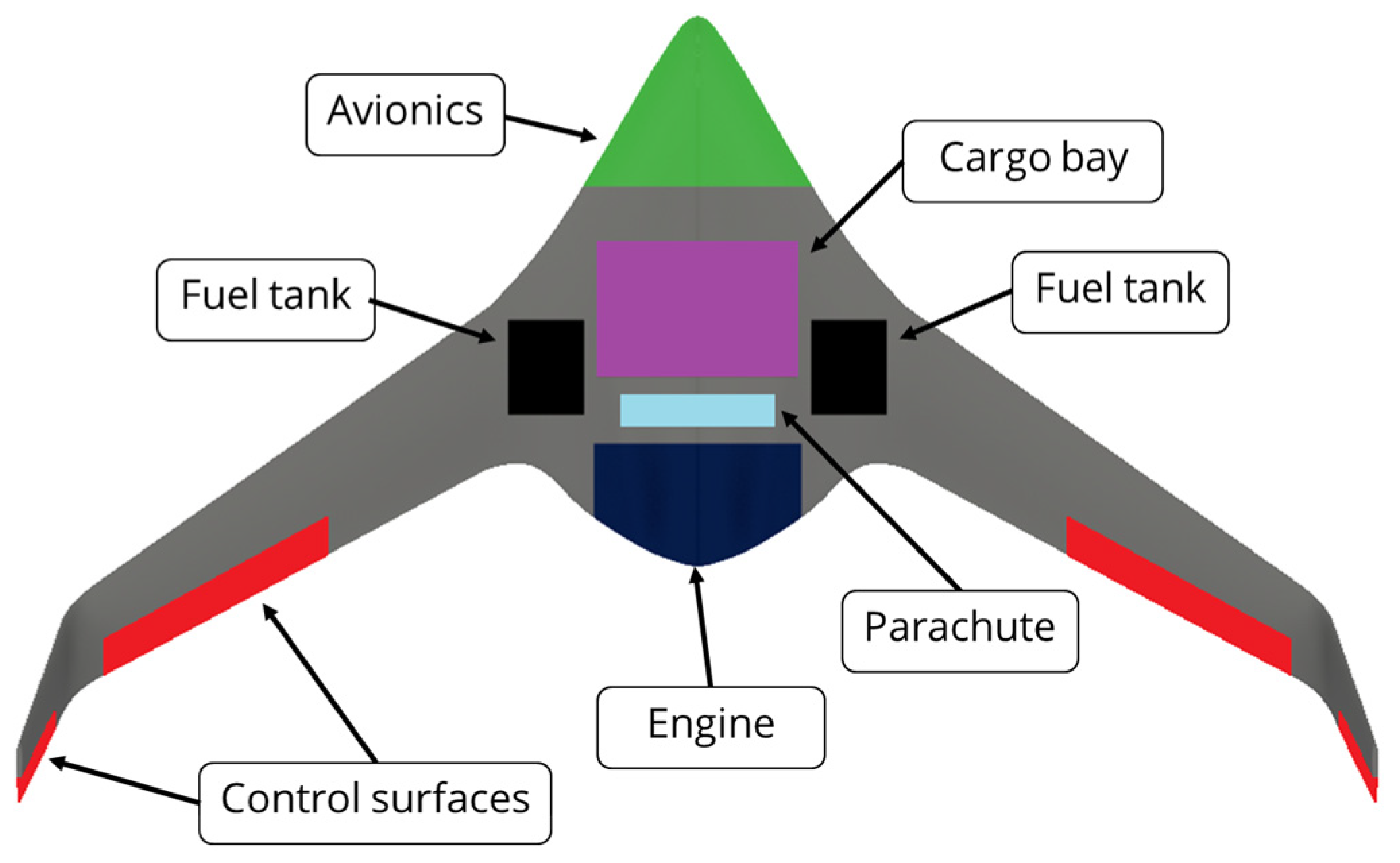
The layout of this UAV is streamlined for efficient cargo transport and incorporates key components within its structure, as seen in Figure 1. At the nose, the avionics compartment houses the control and navigation systems, followed by the centrally positioned cargo bay designed for carrying payloads essential to its delivery mission. Flanking the cargo bay, two fuel tanks are symmetrically located to ensure balanced fuel storage, enhancing stability during flight. The engine is situated at the rear center of the UAV, providing propulsion while being embedded within the body to maintain aerodynamic efficiency. Positioned just in front of the engine, a parachute is included, likely for emergency recovery. Along the wings and winglets, control surfaces, highlighted in red, provide maneuverability and stability, functioning like ailerons, elevators, and rudder equivalents. To accommodate transportation and maintenance requirements, the vehicle’s structure is divided into three primary segments: the main body (fuselage), the wings, and the winglets.
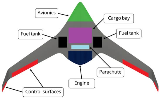
Figure 1.
Internal layout.
2.2. FE Modelling
This study is focused on the design of two segments: the wing and the winglet. Both structures include a front spar near the leading edge, which provides support and rigidity, and a rear spar near the trailing edge, enhancing structural integrity and load-bearing capacity. In this model, both spars feature a “C”-type cross-section, which offers an optimal balance between high bending stiffness and ease of manufacturing due to its open cross-section. The structure also includes nine equally spaced ribs that help maintain the wing’s shape and distribute the pressure loads from the skin to the spars.
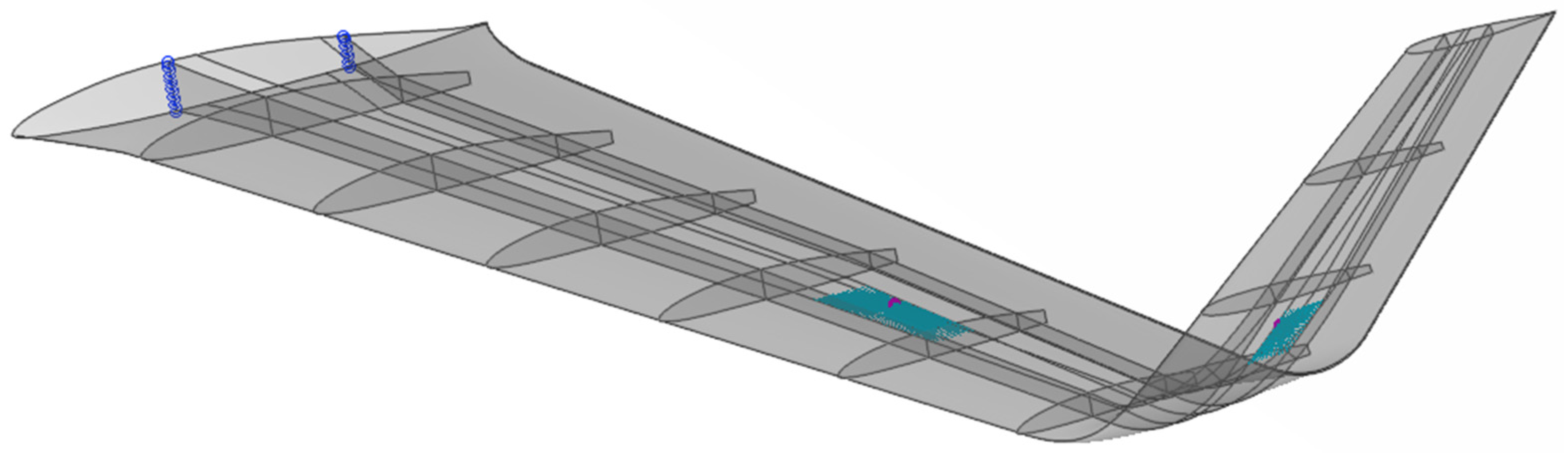
An FE model was developed to analyze the structural behavior of the wing, utilizing a quad-dominated shell mesh (>90%) with 22,000 high-quality elements. The average mesh size is 15 mm for all surfaces. The model includes the weight and position of the control surface systems, each represented as a 1.5 kg point mass element (magenta spheres) connected to the skin through coupling constraints (green “spider” elements), as seen in Figure 2. To simulate realistic operating conditions, appropriate boundary conditions were applied as constraints at the wing root to represent its attachment to the fuselage (blue points). It should be noted that boundary conditions were imposed on the spars to simulate the load path at the highest accuracy.
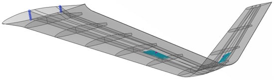
Figure 2.
Wing and winglet structural layout.
The entire structure is made from CFRPs, and two distinct types are used: twill and unidirectional (Table 2). Unidirectional composites have fibers aligned in a single direction, resulting in high strength and stiffness along that direction. This type of material has a significantly higher Young’s modulus in the fiber direction compared to perpendicular to it, along with a moderate shear modulus and a relatively small ply thickness. Twill weave composites, on the other hand, have a more balanced fiber pattern, offering more orthotropic properties than unidirectional materials. They have equal Young’s moduli in the two major directions, a moderate shear modulus, and a slightly thicker ply than the chosen unidirectional composite material.
Table 2.
Used material properties.
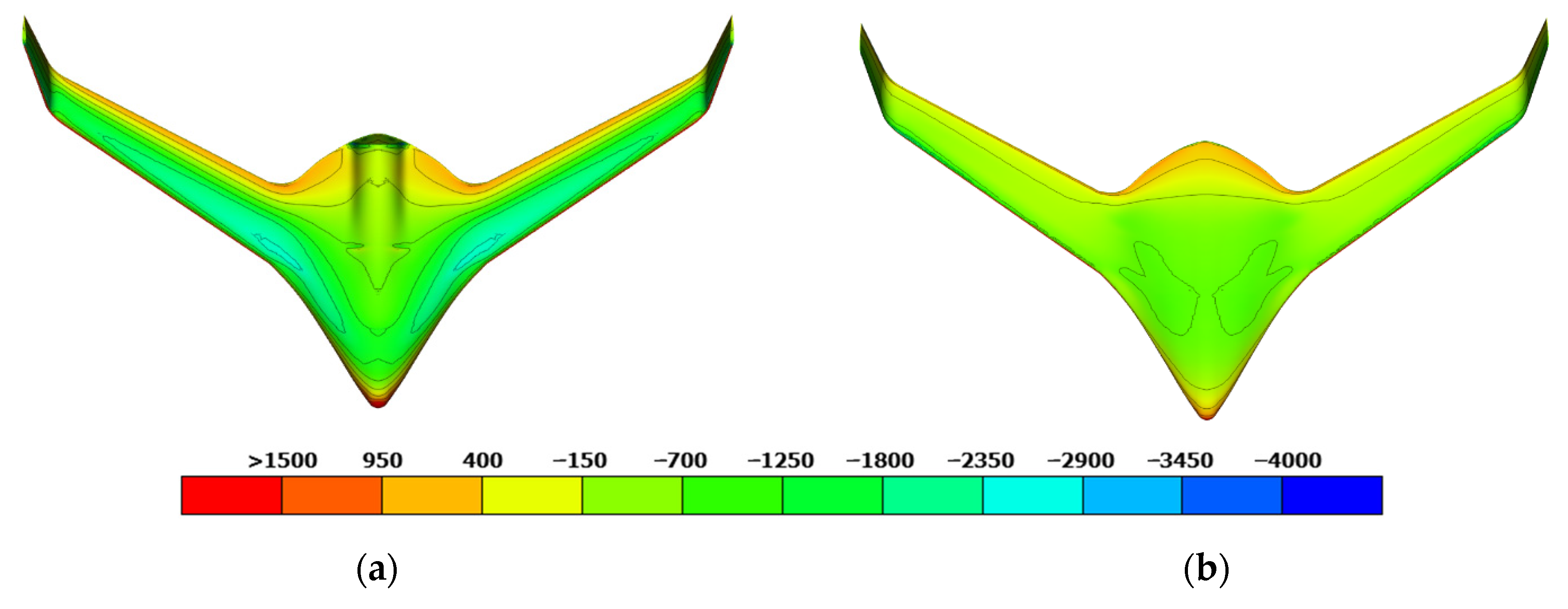
To simulate realistic flight conditions, three load cases were considered: (a) maximum speed, (b) maximum positive turn (Figure 3), and (c) maximum negative turn. The pressure distribution obtained from CFD simulations was mapped to the structural FE mesh to address the mesh mismatch between the CFD and structural models. In addition to pressure, acceleration loads were applied to account for the effects of load factors during each load case.
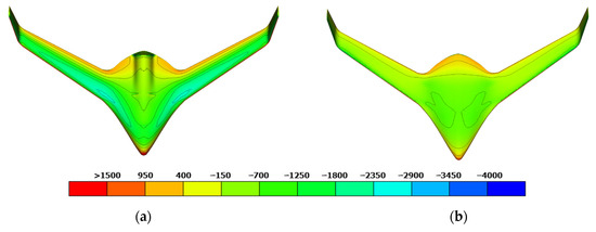
Figure 3.
The pressure distribution [Pa] for the maximum positive turn load case (Angle of Attack: 8°, Load factor: 3.23 g’s). (a) Upper surface; (b) Lower surface.
2.3. Optimization
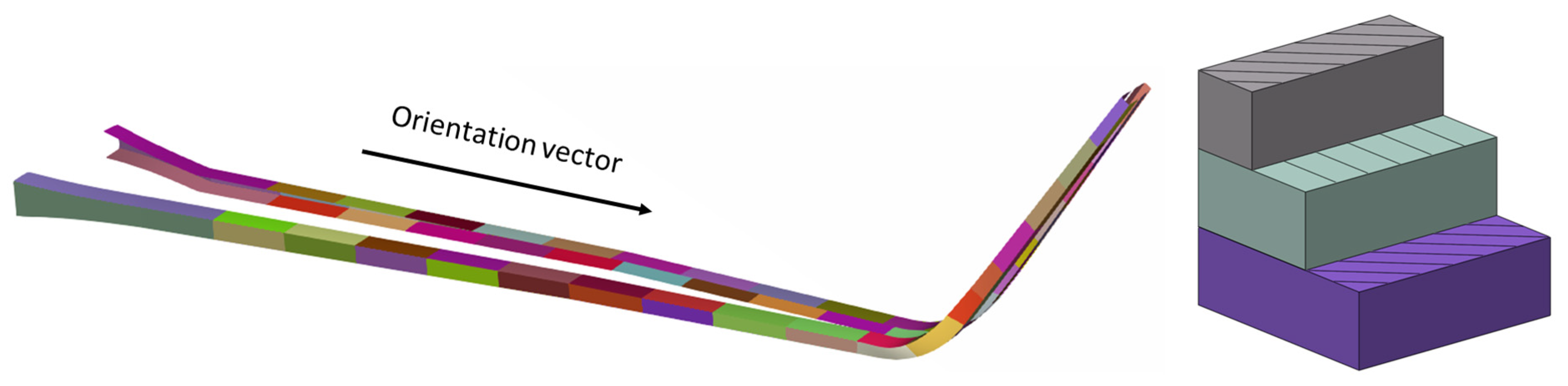
The optimization process begins with the definition of the design variables. The wing skin is modeled with a uniform thickness distribution and comprises three plies, all constructed from twill-type CFRPs. The fiber orientation of the middle ply, on both the upper and lower skins, is chosen as the design variable (DV1). Each spar consists of two plies of twill material, oriented at 45°, and a middle ply of unidirectional material. Both spars are separated into different segments along the width and between the upper and lower surfaces, as presented in Figure 4. The thickness of the middle ply of each segment is presented by a design variable (DV2), while its orientation is constant. The ribs are assigned a fixed thickness (3× twill type) and fiber orientation (45/0/45) and are excluded from the optimization study.
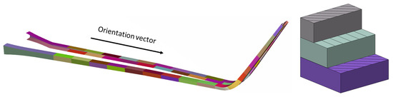
Figure 4.
Design variables of spar elements.
The optimization formulation is structured to achieve the lightest possible design in terms of meeting all performance and safety requirements. In terms of structural performance, the maximum stress failure index criterion is utilized as it is one of the most widely used and less complex methods of predicting failure in composite materials. This stress-based criterion is linear and dependent on failure mode without considering stress interactions [4]. Failure occurs when any stress component exceeds the corresponding strength in tension, compression, or shear.
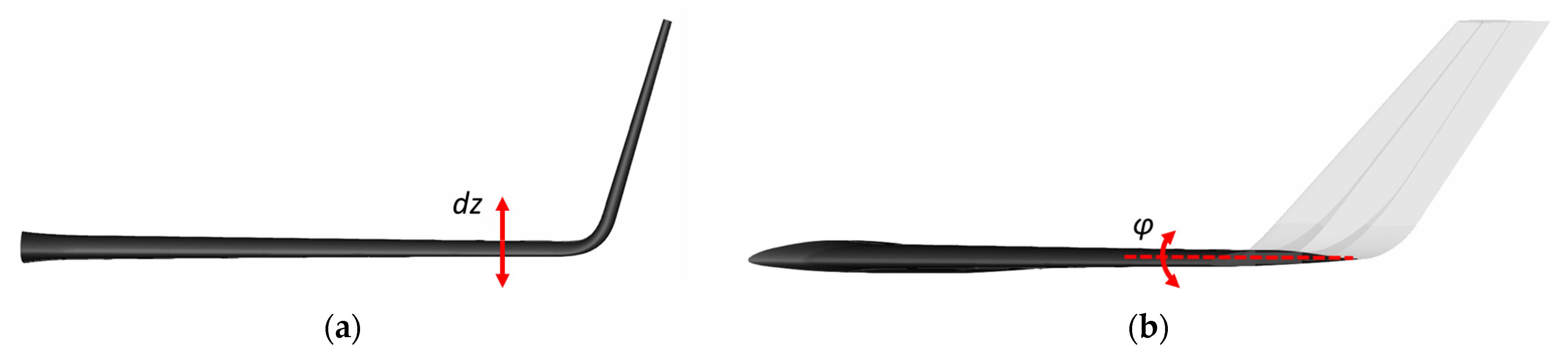
To ensure adequate stiffness behavior, two primary constraints are applied, as seen in Figure 5. The first constraint limits the total vertical displacement of the wing (dz), controlling the extent of deformation under the load. The second constraint regulates the wing’s twist (φ), managing the rotational displacement to maintain aerodynamic stability during operation. Together, these constraints help preserve the wing’s aerodynamic performance under operational conditions.
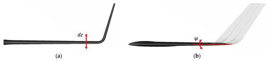
Figure 5.
Optimization constrains: (a) wing deflection; (b) wing twist.
In total, 74 design variables are utilized in the optimization process: 72 variables are allocated to the spars (36 per spar, 2 × 18 for each side), allowing for precise control over spar thickness, while in each skin an individual design variable is included, affecting the orientation of the skin’s middle ply. The optimization statement is formulated as follows:
These criteria ensure adequate wing stiffness for stable aerodynamic performance and structural reliability during flight. Excessive displacement and twist can disrupt airflow, degrade lift, and compromise mechanisms used in ailerons and ruddervators. The limits (100 mm and 1°) were determined via finite element analysis as the maximum allowable deformation that maintains operational safety, aerodynamic stability, and structural integrity under real-world conditions.
It is important to note that the above constraints must be satisfied across all three load cases, resulting in a total of number of nine constraints. The workflow includes several key steps, beginning with the pre-process of the FE model, where the mesh is generated will all required definitions for the FE analysis, the initial weight calculation takes place, and all design variables are defined. Then, the FE solver is employed to analyze the model’s structural response under each load case. Next, the post-processing of the results is conducted to assess design performance against the defined constraints. These procedures are guided by the optimizer, which iteratively uses FE analysis results to adjust the design variables in the stage of the model preparation. Pre- and post-processing were carried out by ANSA and META software (version 23.1.0), the chosen FE solver is ABAQUS (version 2022), and the optimization procedures are led by the Isight Design Gateway (version 2022).
The optimization algorithm used is the Non-Linear Parallel Quadratic Programming (NLPQPL), which is a gradient-based approach well suited for problems involving both equality and inequality constraints. The algorithm iteratively refines the solution by updating the design variables based on local gradient information, focusing on finding an optimal solution within a feasible range surrounding the starting point. This algorithm’s structure is particularly effective for complex engineering problems, as it balances computational efficiency with the ability to handle non-linearities in the design space. In the examined case, each iteration of the optimizer takes approximately 1.5 min to complete, making it suitable for iterative refinement.
3. Results
The total number of iterations is 451, while the number of feasible designs meeting all constraints for all load cases is 65. The optimal solution was found at the last batch at iteration 399.
3.1. Objective Function
The design variables were initially set to their minimum feasible values, resulting in a starting structural weight of approximately 4.6 kg. As the optimization process progressed, adjustments were made by the optimizer, leading to an increase in weight, ultimately reaching around 5.6 kg, as presented in Figure 6. This justified all constraints imposed. This gradual increase reflects the balance between achieving structural efficiency and meeting the constraints.
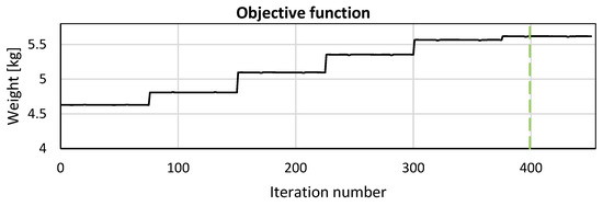
Figure 6.
Weight on each iteration. Dotted line illustrates the optimal solution.
3.2. Failure Index
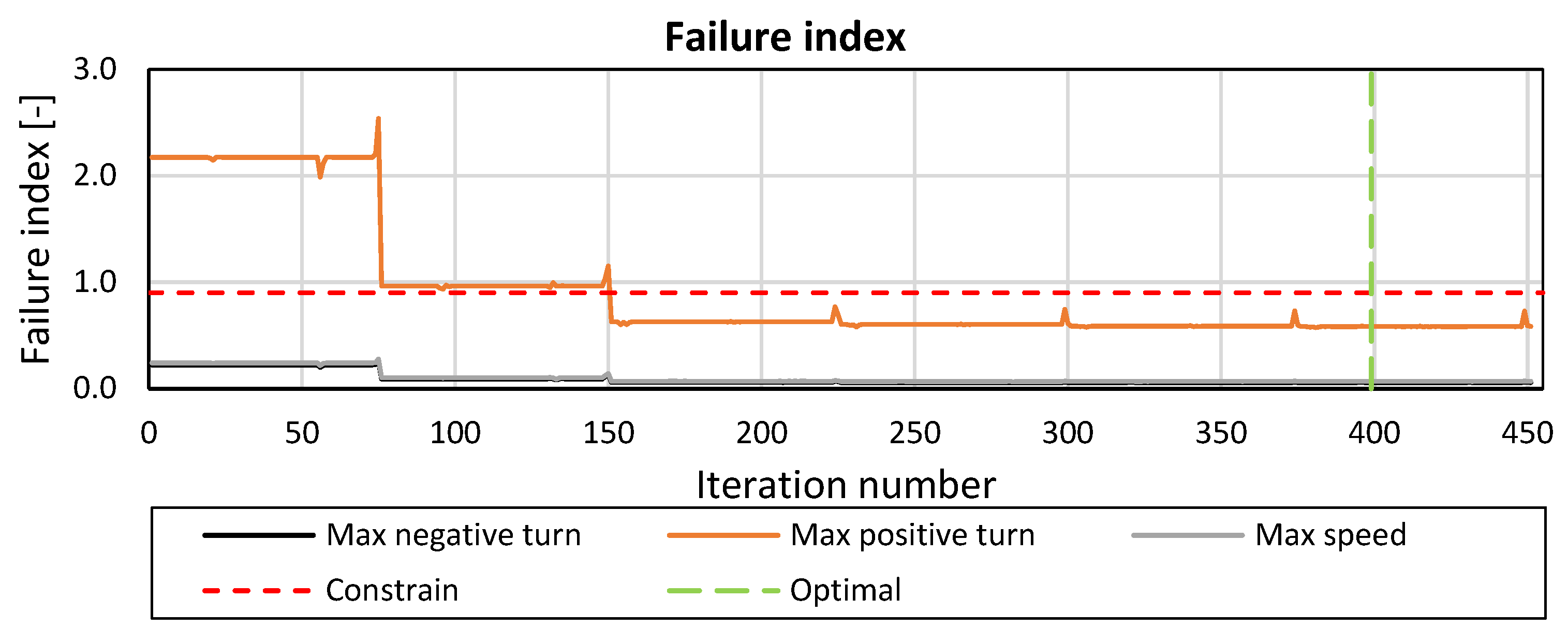
Figure 7 presents the failure index for all load cases. It is evident that the “maximum positive turn” load case represents the most critical loading condition. In the first iterations, the maximum failure index reaches slightly above 2.5. However, in the optimized design, this value is reduced to 0.71, comfortably below the allowable threshold of 0.9. Higher failure index values are observed in areas of the wing that experience greater stress, particularly around the wing root and near the spars, where structural loads are most concentrated.
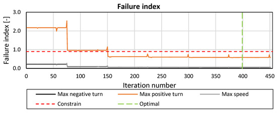
Figure 7.
Maximum failure index on each iteration.
3.3. Translational and Rotational Displacements
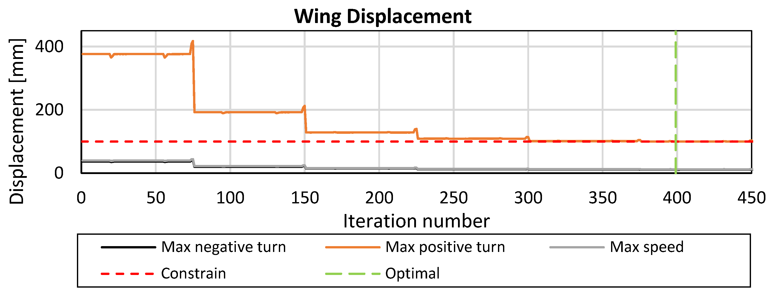
Figure 8 illustrates the translational displacement (dz) of the wing. The maximum allowable displacement is set at 100 mm, making it the most active constraint throughout all optimization processes.
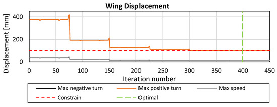
Figure 8.
Wing displacement constrain.
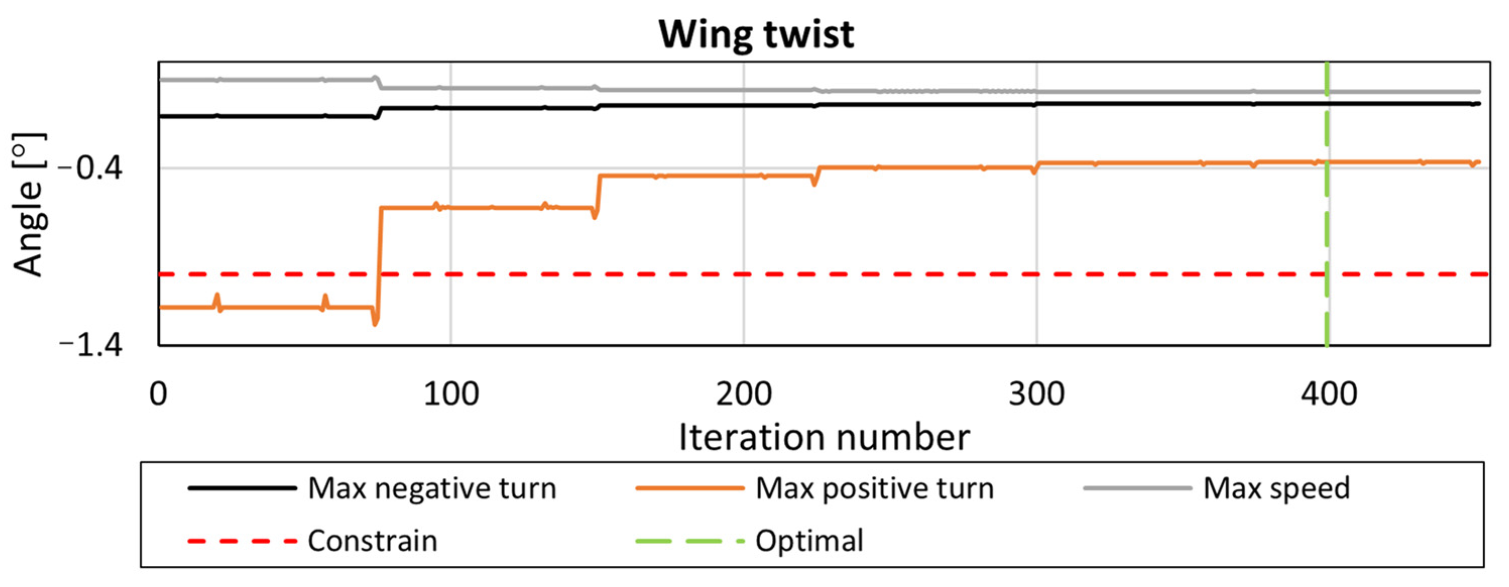
In addition to displacement constraints, the optimization process successfully meets the wing twist constraint by iteration 75, after which the wing twist remains within the allowable limit, as illustrated in Figure 9.
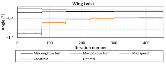
Figure 9.
Wing twist constrain.
3.4. Thickness and Orientation
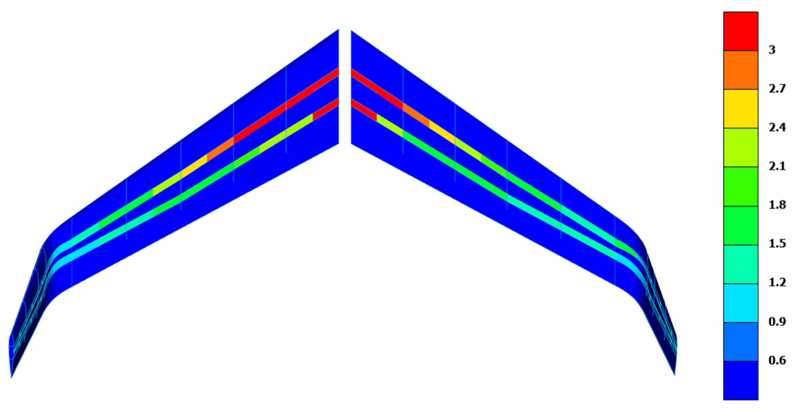
As presented in Figure 10, the resulting thickness is higher at the wing root and gradually decreases toward the tip, reflecting the higher stress levels near the root, as anticipated. The distribution is smooth, which is beneficial for minimizing stress concentrations between the plies. However, the orientation of the skin surfaces remained constant at 0° which concludes that there is no favorable effect of the orientation to the structural behavior of the wing.

Figure 10.
Thickness distribution [mm] for the upper (left) and lower (right) surface of the wing.
4. Conclusions
In this study, a comprehensive software-driven optimization process was implemented to enhance the structural performance of a UAV wing element. The optimization focused on key design variables, including the thickness and orientation of laminated composite structures, essential for achieving lightweight yet structurally stiff wing configurations. The total number of design variables was 74, and the iterations required for optimization were 451. However, the robust FE model setup resulted in 1.5 required minutes for each iteration, leading to an acceptable total running time.
All constraints were satisfied at the end of the optimization, while the displacement constraint was most active during the procedure. Among the three examined load cases, the “maximum positive turn” load case was the most severe. Results revealed a smooth thickness distribution in the spar elements across the wing’s width, contributing to balanced load distribution and minimized stress concentrations. In addition, this smooth transition is a desirable characteristic, as it enhances the wing’s structural integrity without adding unnecessary weight. Interestingly, findings indicated that the orientation of the skin middle plies did not impact the wing’s structural responses. This suggests that, within the tested range, skin ply orientation may have limited influence on the wing’s overall stiffness, allowing future designs to focus on optimizing other variables with greater impact on structural performance.
Author Contributions
Conceptualization, A.P. and G.S.; methodology, A.P.; software, A.P.; validation, A.P.; formal analysis, A.P.; investigation, A.P.; resources, A.P.; data curation, A.P.; writing—original draft preparation, A.P.; writing—review and editing, G.S.; visualization, A.P.; supervision, G.S.; project administration, G.S.; funding acquisition, G.S. All authors have read and agreed to the published version of the manuscript.
Funding
This research received no external funding.
Institutional Review Board Statement
Not applicable.
Informed Consent Statement
Not applicable.
Data Availability Statement
Dataset available on request from the authors.
Conflicts of Interest
The authors declare no conflicts of interest.
References
- Elmeseiry, N.; Alshaer, N.; Ismail, T. A Detailed Survey and Future Directions of Unmanned Aerial Vehicles (UAVs) with Potential Applications. Aerospace 2021, 8, 363. [Google Scholar] [CrossRef]
- Raymer, D. Aircraft Design: A Conceptual Approach, 5th ed.; American Institute of Aeronautics and Astronautics, Inc.: Washington, DC, USA, 2012; ISBN 978-1-60086-911-2. [Google Scholar]
- Kapsalis, S.; Panagiotou, P.; Yakinthos, K. CFD-Aided Optimization of a Tactical Blended-Wing-Body UAV Platform Using the Taguchi Method. Aerosp. Sci. Technol. 2021, 108, 106395. [Google Scholar] [CrossRef]
- Jawaid, M.; Thariq, M.; Saba, N. (Eds.) Failure Analysis in Biocomposites, Fibre-Reinforced Composites and Hybrid Composites; Woodhead Publishing series in composites science and engineering; Woodhead Publishing: Duxford, UK, 2019; ISBN 978-0-08-102301-3. [Google Scholar]

Disclaimer/Publisher’s Note: The statements, opinions and data contained in all publications are solely those of the individual author(s) and contributor(s) and not of MDPI and/or the editor(s). MDPI and/or the editor(s) disclaim responsibility for any injury to people or property resulting from any ideas, methods, instructions or products referred to in the content. |
© 2025 by the authors. Licensee MDPI, Basel, Switzerland. This article is an open access article distributed under the terms and conditions of the Creative Commons Attribution (CC BY) license (https://creativecommons.org/licenses/by/4.0/).