Abstract
Deployment of CubeSat swarms is proposed for various missions necessitating cooperative interactions among satellites. Commonly, the cube swarm requires formation flight and even rendezvous and docking, which are very challenging tasks since they require more energy and the use of advanced guidance, navigation, and control techniques. In this paper, we propose the use of an extensible hook system and its corresponding GNC architecture to mitigate these drawbacks, i.e., it allows for saving fuel and reduces system complexity by including techniques that have been previously demonstrated on Earth. This system is based on a scissor boom structure, which could reach up to five meters for a 4U CubeSat dimension, including three degrees of freedom to place the end effector at any pose within the system workspace. We simulated the dynamic behavior of a CubeSat with the proposed system, demonstrating that the required power for a 16U CubeSat equipped with one extensible hook system is considered acceptable according to the current state-of-the-art actuators.
1. Introduction
CubeSats are miniaturized satellites that can reach a size between 10 cm × 10 cm × 10 cm (1U) and 22.63 cm × 22.63 cm × 45.4 cm (16U) and a mass lower than 25 kg for a 16U CubeSat. Based on standardization, their development is commonly fast and cheap. Initially, they were used for education and research, evolving toward a platform to demonstrate early technologies. However, they are increasingly used for commercial applications [1].
It is common to launch a CubeSat alone or in constellations; however, the use of a CubeSat swarm arises as a novel method for operating as a single spacecraft with many advantages, i.e., scalability, robustness, etc. However, guidance, navigation, and control (GNC) of a CubeSat swarm is a very challenging task, requiring the use of novel methods and technologies. The field of guidance requires the use of complex motion planning methods that allow the coordination of the CubeSat swarm by generating trajectories to achieve a particular formation in space. Navigation requires knowing the 6 degrees of freedom (DoF) pose of each satellite by combining different proprioceptive and exteroceptive sensors. Finally, control must guarantee that the generated trajectory is followed by controlling the actuators.
Currently, CubeSat swarms have been proposed for different applications. For example, in [2], the authors proposed the use of a distributed CubeSat swarm to perform low-frequency radio astronomy, placing it orbiting the moon. The SWIMSat mission [3] proposed a CubeSat swarm placed in low-earth orbit (LEO) to monitor meteor impacts on the sky above North America. Finally, a CubeSat swarm has also been proposed in different missions related to Earth observation [4], highlighting the European Space Agency (ESA) Swarm mission to study the dynamics of the Earth’s magnetic field [5].
As stated before, CubeSats swarms have been investigated for different missions, taking advantage of the configurations to accomplish their objectives. However, emerging applications in space, such as active debris removal (ADR) [6] and space-based solar power (SBSP) [7] will require orbital rendezvous and docking (RVD) operations to capture debris or create space infrastructures. In the latter case, RVD can be achieved by attaching several satellites, e.g., the AAReST mission [8], with the objective of assembling a space telescope based on four 3U CubeSats that are docked. Other applications would require keeping the CubeSats connected to each other without requiring RVD. For example, building large structures in space, such as the one proposed for SBSP [9], could be made using a CubeSat swarm. In these cases, a hook system would be required to connect the CubeSat to each other, forming the required structure. Furthermore, an extensible hook system (EHS) provides an advantage related to avoiding the use of thrusters (propellant saving) in two scenarios: when RVD is required, the approaching stage can be completed by the EHS, and during a formation flight, where the EHS can be used to keep the CubeSat swarm aligned.
In this sense, this paper proposes an EHS concept based on a scissor boom. This concept has previously been proposed to be used for different applications in CubeSats. For example, extending a set of sensors 13 cm from the CubeSat [10], with the objective of avoiding electronic interference with the sensors, or deploying solar array systems [11]. In this paper, we propose the use of a scissor boom mechanism to connect a CubeSat swarm that conforms to a hexagonal structure, as can be seen in Figure 1. In order to create this structure, not only the aforementioned mechanism is needed, but also the GNC system to link the CubeSats in the optimal way, which will be addressed in this paper by proposing some state-of-the-art methods that could solve the main issues.
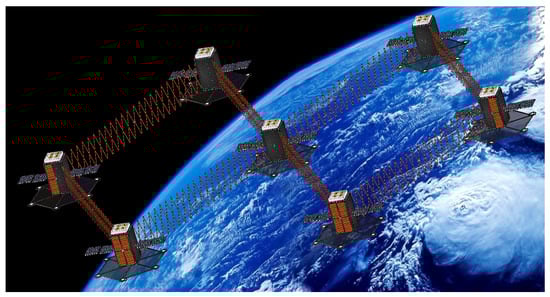
Figure 1.
Deployed CubeSat swarm with the extensible hook system.
2. Extensible Hook System Design
The proposed EHS is based on a scissor boom structure with different DoF according to the mission requirements and CubeSat structures. Figure 2 shows an initial design of the proposed system. It has been chosen due to its mechanical simplicity and capacity to be extended a greater distance than other structures, such as simple manipulators. However, analysis of the lateral stability is pending according to the materials used and the particular application. The proposed system is initially provided with three joints (3DoF): The first joint allows the system to extend and retract the end effector, actuating on the bar that holds the scissor structure. The second joint allows the main scissor structure to be re-oriented. Finally, the whole EHS can be rotated by the third joint. These three DoF allow one to place the end effector at any position within the EHS workspace.
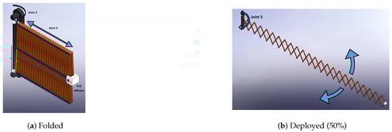
Figure 2.
Proposed scissor boom-based extensible hook system with 3 joints.
According to this configuration, Equation (1) represents the position of the end effector (x) w.r.t. the prismatic joint (y) on the actuation bar, which depends on the half length of the link (), the distance between the actuation bar to the first link (), the distance between the last link and the contact point of the end effector (), and the number of pairs of intermediate links (N). It is worth mentioning that this equation includes non-linearities that should be taken into consideration to design the joint controller.
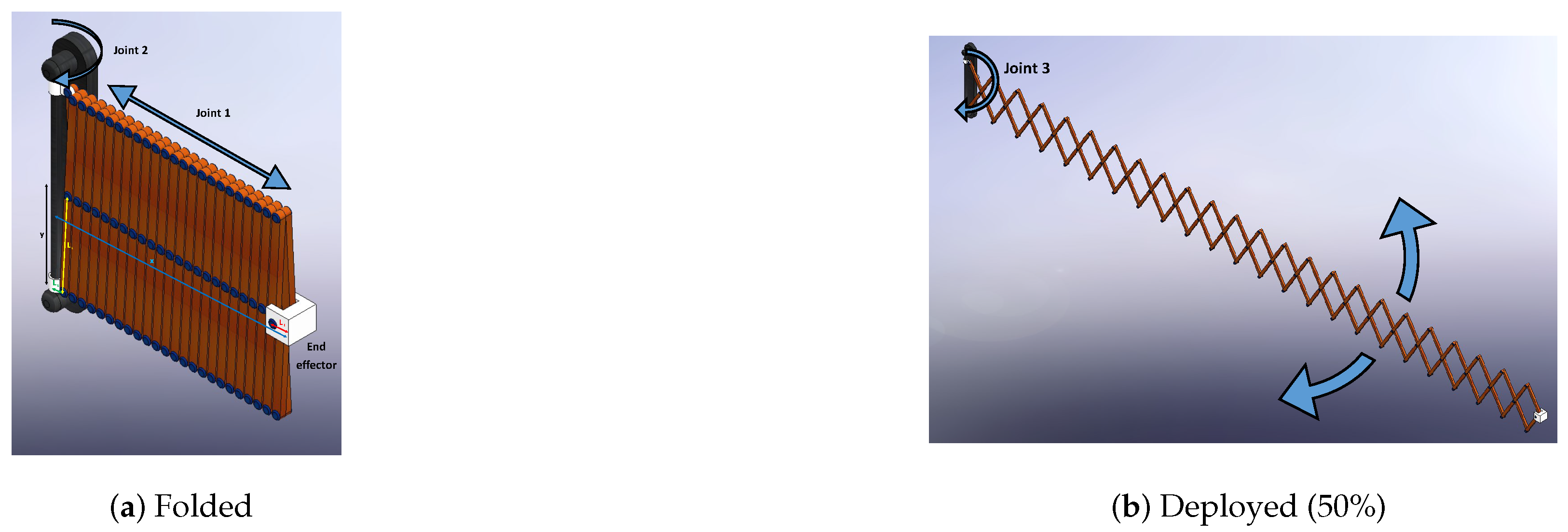
Based on this configuration, the EHS has been adapted for mounting on a CubeSat with a 4U total size, i.e., 10 cm × 10 cm × 45.4 cm. This configuration allows the EHS to be extended up to 5 m, allowing up to four EHS (two per side) in a 16U CubeSat. Figure 3 illustrates the configuration described previously, in which two EHSs are placed on two sides. The EHS could be adapted to different applications by reducing its size and, therefore, its reachability. However, in this paper, the main objective of this EHS is to be able to connect the CubeSat swarm from a 10 m distance, keeping them connected in a formation flight.
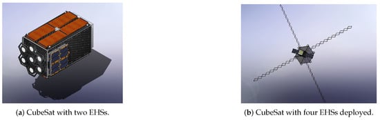
Figure 3.
CubeSat configuration with four EHSs folded and deployed.
The end effector will be based on a configuration with permanent and electromagnets, allowing them to connect EHSs between them, using the electromagnets to increase the power during the docking stage or to compensate the permanent magnets for undocking both CubeSats. A clear example of this configuration has been published with applications on drones [12], where they were equipped with permanent magnets that attracted each other to create a unique structure in the air. The main drawback of using magnetic fields is that it could affect CubeSat sensors, such as magnetometers, which are commonly used for CubeSat navigation.
3. Guidance, Navigation, and Control
To perform CubeSat RVD using the EHS, the GNC subsystem needs to be defined for this purpose. The main requirement of it is to ensure that the CubeSats can locate each other with low to high accuracy depending on their distance. Conversely, the guidance component must develop a motion plan for the CubeSat swarm to integrate their trajectories so they can establish connectivity via the EHS. Subsequently, all CubeSat actuators need to be controlled to follow the defined motion plan by the guidance component.
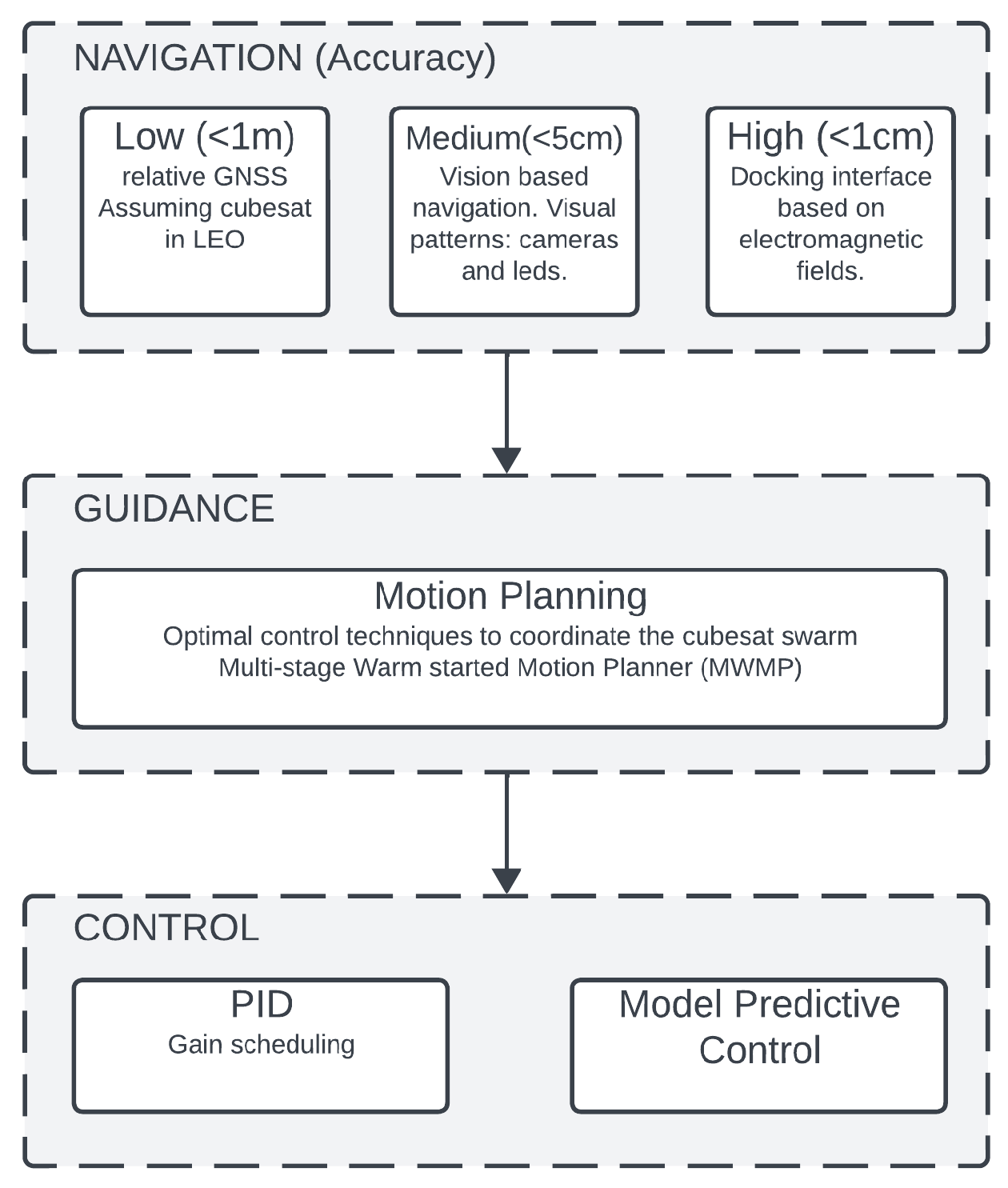
Figure 4 illustrates the proposed GNC subsystem. Firstly, the navigation component has been split into three stages, each of which requires lower or higher accuracy. When the CubeSats are far (>5 m), low accuracy is required (<1 m). This precision can be reached using Global Navigation Satellite Services (GNSS), which, in the case of relative localization in LEO, can reach 0.5 m and below [13]. Once the CubeSats are approaching, the navigation component will require a higher accuracy (<5 cm). For this purpose, our proposal would be to include a vision-based navigation system, which would be made up of LED patterns and cameras. Using this information, the localization of the CubeSat swarm could be completed with an accuracy on the order of 1 cm [14]. Finally, when the CubeSats are about to dock using the EHS, high-resolution localization is needed. In this case, localization is replaced by electromagnetic fields on the EHS end effector that will generate the corresponding forces to attract both end effectors by hooking them.
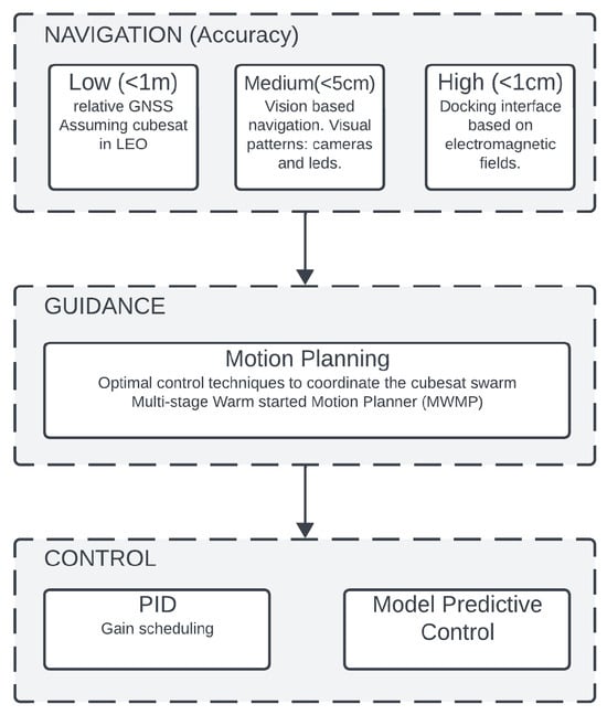
Figure 4.
Proposed guidance, navigation, and control architecture.
Regarding the guidance component, it requires the performance of motion planning for the CubeSat swarm, including the EHS. Our proposal would be to use a motion planner that allows the swarm to plan the CubeSat motion, taking into consideration nonlinearities and constraints. Multi-staged warm-started motion planners arise as a solution to be evaluated. The main advantage of this method is that it allows one to compute an optimal plan faster with an increased success calculation [15], i.e., these planners sometimes are not able to find a solution.
Finally, control requires commanding the CubeSat to follow the predefined motion plan by the guidance component, as well as controlling all of the actuators, including those that belong to the EHS. According to Equation (1), the extensible joint (joint 3 in Figure 2a) is non-linear; therefore, a classical PID controller cannot be used for that purpose. Our proposal would be to evaluate the use of model predictive control (MPC) and gain scheduling. The first one has the advantage of allowing control of the actuator, taking into consideration a realistic model and predicting its behavior; however, it requires more computation. Alternatively, gain scheduling does not require a lot of computation, but the control is simpler.
4. Simulation Results
The design of the EHS requires tvalidation through simulation. They provide valuable information about the required forces, torques, and energy to move the CubeSat and the EHS, allowing them to choose the best actuators, i.e., thrusters and motors. The parameters used for CubeSat and EHS are shown in Table 1.

Table 1.
CubeSat parameters during simulation.
The actuators were controlled by adjusting a proportional, integrative, and derivative (PID) controller, and a trapezoidal trajectory generator was included in the model to perform the simulations.
The simulations were performed using Matlab Simscape Multibody. This tool allows us to assemble all the pieces that were previously designed using SolidWorks v2023 and simulate their dynamics by solving the whole mechanic system equations. Moreover, this tool allows us to generate animations of the system, and it can be used to test different controllers by using the hardware and software in the loop concepts.
During the simulation, guidance and navigation were omitted; due to their complexity, they are proposed as future work. Navigation was replaced by the absolute localization that provides the simulator, and control was implemented using PIDs and gain scheduling for the case of joint 3 of the EHS.
To validate the proposed system, two simulations were carried out. The first one related to moving the CubeSat from an initial pose to a final one, and the second simulation was related to the extension of the EHS and the required forces and torques to perform the motion.
4.1. CubeSat Trajectory Tracking
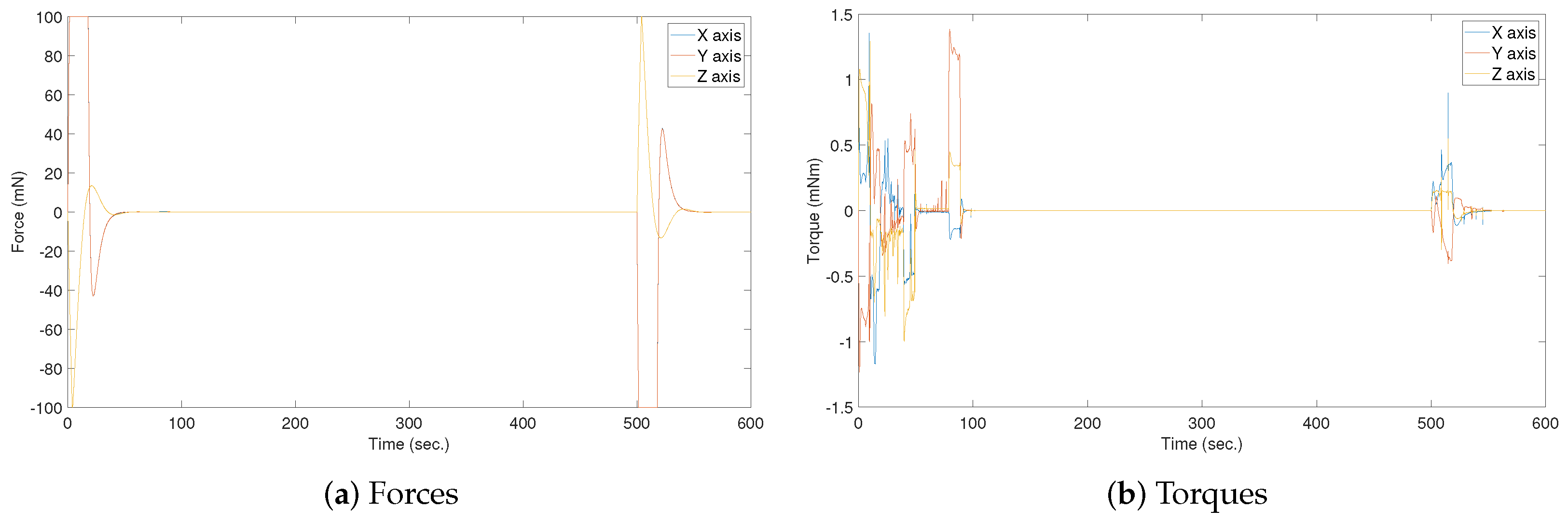
During this simulation, the objective was to measure the required forces and energy to perform a maneuver that would place the CubeSat in a particular pose. The simulation was configured to move the CubeSat from to (25 m, 25 m, m, rad, rad, rad) in position and orientation coordinates, traversing a distance of 36.7523 m in 500 s. Figure 5 shows the obtained results, where the displacement required a maximum longitudinal force of 100 mN on the Y axis, and a maximum torque of 1.385 for a rotation on the Y axis. Moreover, the motion required a total energy of Ns, Ns, Ns) for X, Y, and Z.
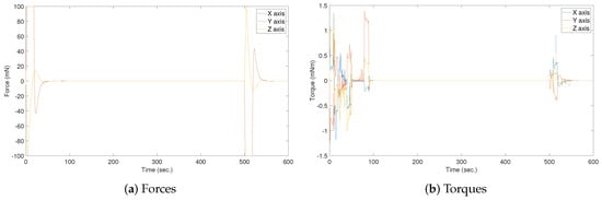
Figure 5.
Required torques and forces to move the CubeSat 36.7523 m in 500 s following a trapezoidal profile.
4.2. Extensible Hook System Deployment
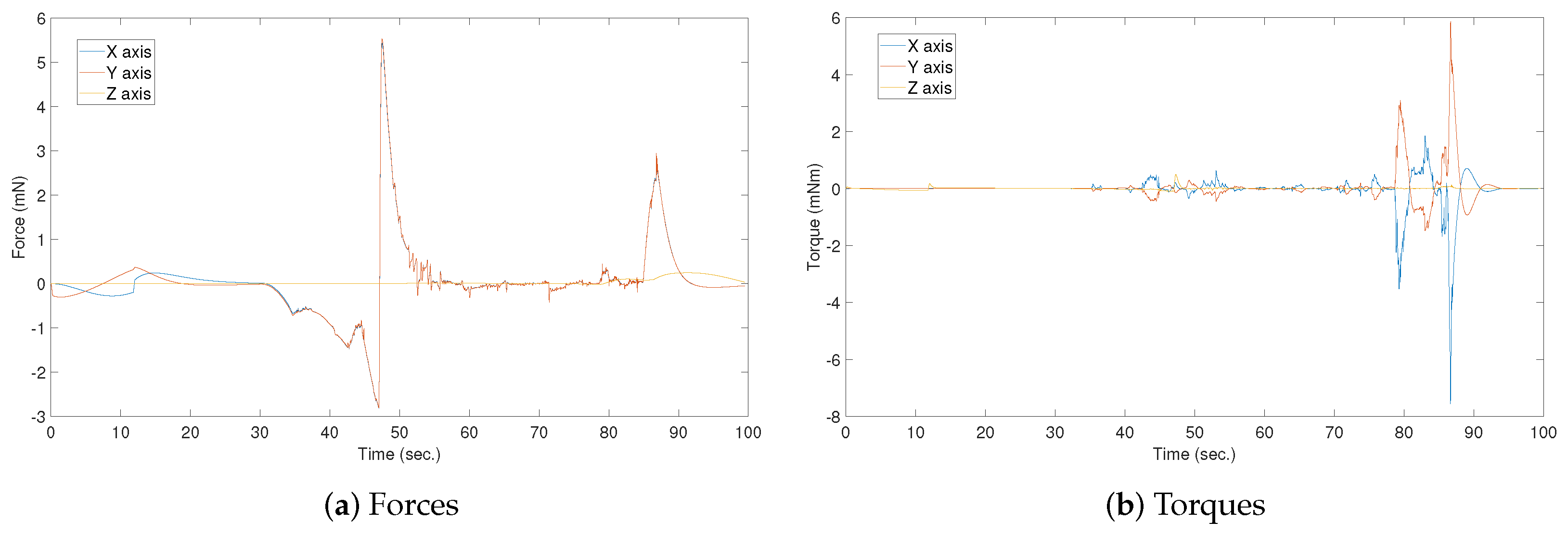
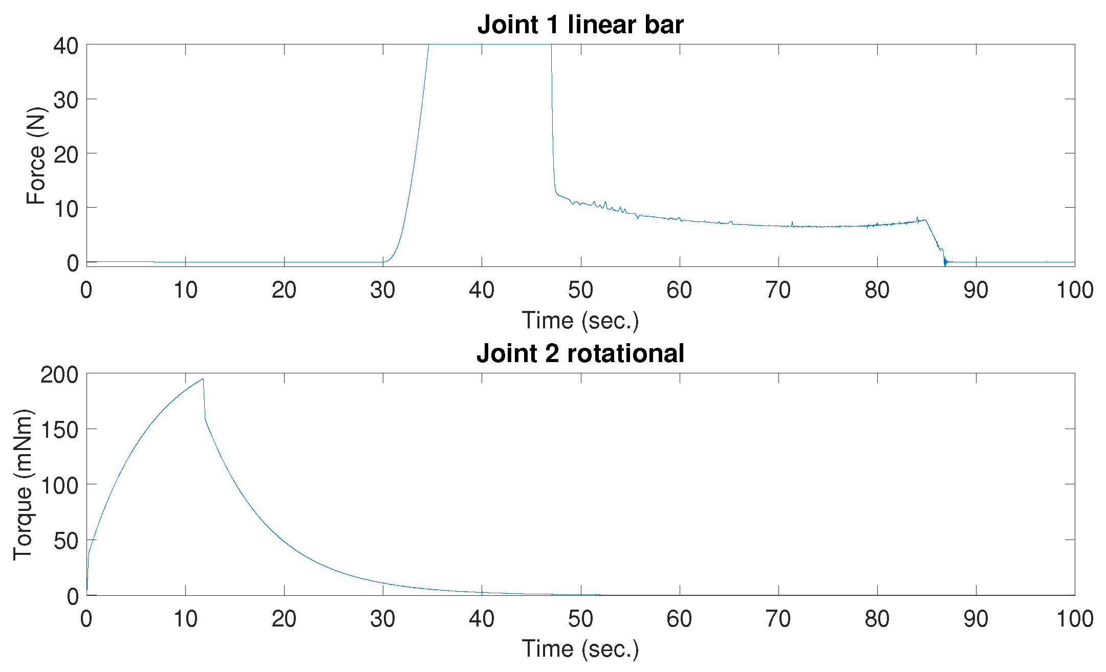
To demonstrate the required forces to move the EHS, the CubeSat was controlled to keep the initial pose, while the EHS was rotated 135º and deployed 4.5 m. Figure 6 shows the resulting force and torque to keep the CubeSat in a fixed pose. As can be seen, the maximum required forces were 5.527 mN for the X and Y axes and 2.942 mN for the Z axis. The system required a total energy of mNs, mNs, mNs) for the X, Y, and Z axes, respectively. The maximum required torque was mNm, mNm, mNm) for the X, Y, and Z axes. On the other hand, the actuator of joint 1 from the EHS was limited to 40 N, and joint 2 required a maximum torque of 194.1 mNm, as shown in Figure 7.
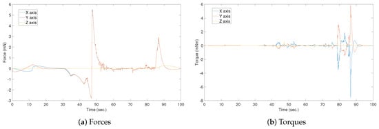
Figure 6.
Required torques and forces to keep the CubeSat in a fixed pose during the motion of the EHS.
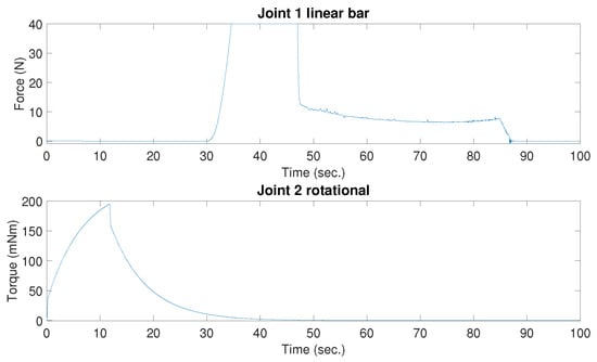
Figure 7.
Required force and torque to rotate and deploy the EHS.
4.3. Docking and Approaching Two CubeSats
During this simulation, we include two CubeSats with the EHS. They started from an initial position and followed a trajectory to reach a position where they were 8.6 m from each other. Then, they started the approach stage until they reached 3.2 m, in which they used the EHS to move themselves closer.
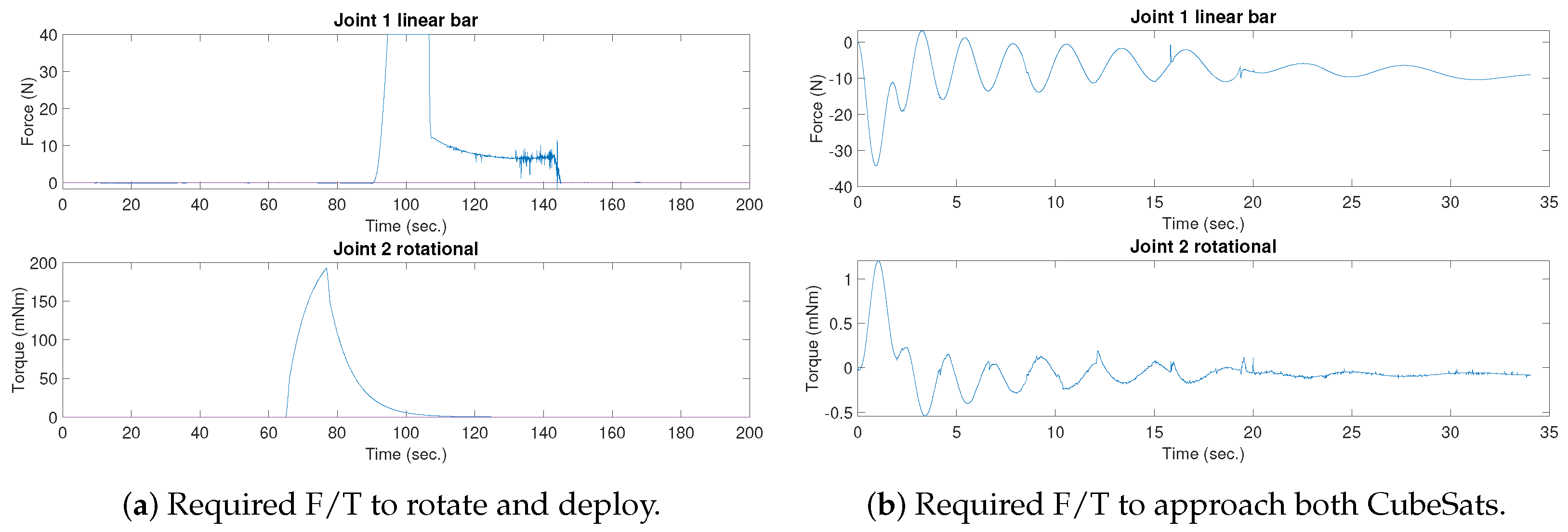
Figure 8 shows the required forces and torques to move the CubeSat and deploy the EHS. On the other hand, Figure 9a shows the required forces and torque from the EHS to be deployed and extended.
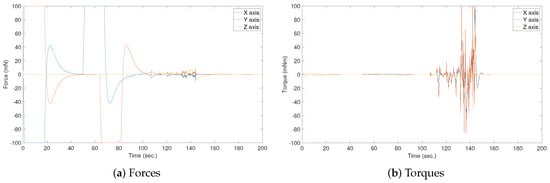
Figure 8.
Required torques and forces to move the CubeSats and hold them while the EHS is deployed.
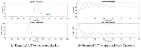
Figure 9.
Required EHS joint forces and torques (F/T).
Once both CubeSats were docked, the EHS was used to approach them. Figure 9b shows the required force and torque from one of the EHSs to approach both CubeSats.
5. Discussion
As stated in this paper, the proposed EHS will support RVD and flight formation, saving propellant and energy. Moreover, the obtained results demonstrate that it is feasible to provide the required energy to move the CubeSat and the EHS by commercial actuators in a LEO environment.
The proposed EHS (Figure 3) is able to reach up to 5 m of distance, allowing both CubeSats to be connected, even when they are up to 10 m from each other. However, this limited configuration provides some drawbacks related to the size and mass of the EHS. In particular, if the EHS was made of aluminum, its mass would be around 2 kg without considering electronics and motors, which could increase this mass to 2.5–3 kg. Considering that the CubeSat would require four EHSs, its mass could reach up to 12 kg. Considering the available payload mass for a 16U CubeSat is 18–20 kg, around half of its weight should be dedicated to the EHS. Based on this statement, the best recommendation would be to reduce the maximum distance of the EHS to 2.5 m. In this case, the mass would be almost the half, with a total mass around 6–8 kg, considering 5 m distance between CubeSats as a feasible solution. Using this reduced configuration, the CubeSat would be configured in a long 4U format, or even in a 2U format, occupying less space.
6. Conclusions
This paper proposed an EHS that allows a CubeSat swarm to be connected with the main objective of saving thruster propellant. This propellant saving could be achieved in two stages: during the approaching stage, by bringing the CubeSat closer, and the formation flight, keeping the CubeSat swarm together by the use of the EHS that connects the parts together.
However, the use of the EHS in combination with the CubeSat actuators requires an advanced GNC. This paper proposed a three-level navigation component by combining GNSS, vision-based navigation, and electromagnets for the docking stage. In the case of guidance, it requires complex motion planning methods to coordinate the CubeSat swarm. Finally, control requires classical PIDs in combination with other advanced techniques, such as gain scheduling and MPC due to the non-linearities in the EHS.
The proposed system was simulated using Matlab Simscape Multibody, obtaining meaningful information about the required forces and torques to move the CubeSat and the EHS. The obtained measurements are realistic, i.e., they can be generated by thrusters, reaction wheels, and motors. It is pending the selection of the particular actuators according to the obtained measurements.
The proposed concept has been designed and evaluated from a mechanical and dynamic point of view; however, it is pending investigating and development of the GNC stack, which would allow a CubeSat swarm to be connected through the proposed system. This challenge is proposed as future work, with the aim of using the current simulation environment to test the GNC stack using the software in the loop concept.
Author Contributions
C.P.-d.-P. conceptualization, methodology, investigation, and writing; A.L.P. formal analysis and software; J.J. conceptualization and formal analysis; M.M. supervision, project administration, and funding acquisition. All authors have read and agreed to the published version of the manuscript.
Funding
This research was funded by Sirin Orbital Systems AG as prime of the ESA activity: Swarm of 16U CubeSats for Space-Based Solar Power (16U4SBSP).
Conflicts of Interest
The authors declare no conflicts of interest.
References
- Golkar, A. Overview of the New Space CubeSat market. In Next Generation CubeSats and SmallSats; Elsevier: Amsterdam, The Netherlands, 2023; pp. 605–620. [Google Scholar]
- Budianu, A.; Meijerink, A.; Bentum, M.J. Swarm-to-Earth communication in OLFAR. Acta Astronaut. 2015, 107, 14–19. [Google Scholar] [CrossRef]
- teja Nallapu, R.; Kalita, H.; Thangavelautham, J. On-Orbit Meteor Impact Monitoring Using CubeSat Swarms. In Proceedings of the Advanced Maui Optical and Space Surveillance Technologies Conference, Maui, HI, USA, 11–14 September 2018; p. 11. [Google Scholar]
- Liu, S.; Theoharis, P.I.; Raad, R.; Tubbal, F.; Theoharis, A.; Iranmanesh, S.; Abulgasem, S.; Khan, M.U.A.; Matekovits, L. A survey on CubeSat missions and their antenna designs. Electronics 2022, 11, 2021. [Google Scholar] [CrossRef]
- van den IJssel, J.; Encarnação, J.; Doornbos, E.; Visser, P. Precise science orbits for the Swarm satellite constellation. Adv. Space Res. 2015, 56, 1042–1055. [Google Scholar] [CrossRef]
- Pirat, C.; Richard-Noca, M.; Paccolat, C.; Belloni, F.; Wiesendanger, R.; Courtney, D.; Walker, R.; Gass, V. Mission design and GNC for in-orbit demonstration of active debris removal technologies with CubeSats. Acta Astronaut. 2017, 130, 114–127. [Google Scholar] [CrossRef]
- Curreri, P.A.; Detweiler, M.K. A Contemporary Analysis of the O’Neill-Glaser Model for Space-Based Solar Power and Habitat Construction. NASA Technical Report. Available online: https://ntrs.nasa.gov/citations/20120001744 (accessed on 12 March 2025).
- Underwood, C.; Pellegrino, S.; Lappas, V.J.; Bridges, C.P.; Baker, J. Using CubeSat/micro-satellite technology to demonstrate the Autonomous Assembly of a Reconfigurable Space Telescope (AAReST). Acta Astronaut. 2015, 114, 112–122. [Google Scholar] [CrossRef]
- Pelton, J.N.; Pelton, J.N. Space-based solar power satellite systems. In Space 2.0: Revolutionary Advances in the Space Industry; Springer: Berlin/Heidelberg, Germany, 2019; pp. 103–114. [Google Scholar]
- Fish, C.; Swenson, C.; Crowley, G.; Barjatya, A.; Neilsen, T.; Gunther, J.; Azeem, I.; Pilinski, M.; Wilder, R.; Allen, D.; et al. Design, development, implementation, and on-orbit performance of the dynamic ionosphere CubeSat experiment mission. Space Sci. Rev. 2014, 181, 61–120. [Google Scholar] [CrossRef]
- Trabert, R.; Klesh, A.; Senatore, P.; Martinchek, P.; Becker, D.; Chou, A.; Hoffman, C.; Hoffman, C.; McKay, N.; Nash, J.; et al. The extendable solar array system: A modular nanosatellite power system. In Proceedings of the AIAA/AAS Astrodynamics Specialist Conference, Toronto, ON, Canada, 2–5 August 2010; p. 7654. [Google Scholar]
- Saldana, D.; Gabrich, B.; Li, G.; Yim, M.; Kumar, V. Modquad: The flying modular structure that self-assembles in midair. In Proceedings of the 2018 IEEE International Conference on Robotics and Automation (ICRA), Brisbane, QLD, Australia, 21–25 May 2018; pp. 691–698. [Google Scholar]
- Giralo, V.; D’Amico, S. Distributed multi-GNSS timing and localization for nanosatellites. Navigation 2019, 66, 729–746. [Google Scholar] [CrossRef]
- Pirat, C.; Ankersen, F.; Walker, R.; Gass, V. Vision based navigation for autonomous cooperative docking of CubeSats. Acta Astronaut. 2018, 146, 418–434. [Google Scholar] [CrossRef]
- Paz-Delgado, G.J.; Pérez-del Pulgar, C.J.; Azkarate, M.; Kirchner, F.; García-Cerezo, A. Multi-stage warm started optimal motion planning for over-actuated mobile platforms. Intell. Serv. Robot. 2023, 16, 247–263. [Google Scholar] [CrossRef]


Disclaimer/Publisher’s Note: The statements, opinions and data contained in all publications are solely those of the individual author(s) and contributor(s) and not of MDPI and/or the editor(s). MDPI and/or the editor(s) disclaim responsibility for any injury to people or property resulting from any ideas, methods, instructions or products referred to in the content. |
© 2025 by the authors. Licensee MDPI, Basel, Switzerland. This article is an open access article distributed under the terms and conditions of the Creative Commons Attribution (CC BY) license (https://creativecommons.org/licenses/by/4.0/).