Proceeding Paper

The Aerodynamic Design of a Compliant Morphing Flap for Next-Generation Hybrid Electric Regional Aircraft †

by
Francesco Antonio D’Aniello
*,
Pietro Catalano
,
Domenico Quagliarella
and
Mauro Minervino
CIRA Italian Research Aerospace Centre—Via Maiorise SNC, 81043 Capua, Italy
*
Author to whom correspondence should be addressed.
Presented at the 14th EASN International Conference on “Innovation in Aviation & Space towards sustainability today & tomorrow”, Thessaloniki, Greece, 8–11 October 2024.
Eng. Proc. 2025, 90(1), 13; https://doi.org/10.3390/engproc2025090013
Published: 11 March 2025

Abstract

:
The focus of this paper is on some of the activities performed by CIRA under the framework of the HERWINGT project (Hybrid Electric Regional Wing Integration Novel Wing Technologies) supported by the Clean Aviation Joint Undertaking and funded by the European Union. The aim of the project is to design an innovative wing suitable for future hybrid electric regional aircraft (HER) that will contribute to the overall target of reducing fuel burn, CO2, and other GHG emissions by improving aerodynamic efficiency and reducing weight. The aerodynamic design of a high-lift system of wings in the form of a compliant morphing flap is presented in this paper. A morphing flap was designed through CIRA’s in-house-developed evolutionary optimization software employing the SU2 open source RANS flow solver. The required performances can be achieved by a configuration equipped with both flap and droop noses, with flow control applied to mitigate the separation occurring over the rear upper region of the wing section. This has become particularly important for landing performances. Analyses were conducted for a 2D wing section. Requirements for the flow control system in terms of mass flow and maximum extension of the separated region were formulated.

1. Introduction

In recent decades, the importance of reducing fuel burn, in order to reduce CO2 and other GHG emissions, has become increasingly necessary. The HERWINGT project (Hybrid Electric Regional Wing Integration Novel Wing Technologies), supported by the Clean Aviation Joint Undertaking and funded by the European Union, aims to fulfil the requirements of greening civil and general aviation. One of the most investigated engineering solutions is distributed electric propulsion (DEP), which comprises multiple small fans or propellers driven by electric motors. The DEP concept led to the HERWINGT project, whose aim is to design an innovative wing suitable for future hybrid electric regional (HER) aircraft. To achieve reduced emissions, the developed wing must reach the three wing-level targets of improving aerodynamic efficiency by 12%, reducing weight by 20%, and reducing the take-off power by 50%, which translate to 12%, 3%, and 1%, respectively, in order to obtain an overall target of 15% by reducing overall aircraft fuel burn.
CIRA and the Delft University of Technology (TUD) were involved in the framework of work package 1.2 of the HERWINGT project by contributing to the design and development of a high-aspect-ratio wing. CIRA and TUD produced an aero-structural design of two high-aspect-ratio wings. A cantilever wing was designed by CIRA [1], and a strut-braced one was designed by TUD. Both wings were subject to a trade-off analysis performed by LEONARDO. The aerodynamic performances in cruise and in climb conditions and the structural analysis and verification were compared. The strut-braced wing designed by TUD was chosen as the wing of the configuration to be developed in the HERWINGT project. This paper describes the aerodynamic design of a high-lift system of the HERWINGT wing and, in particular, of a compliant morphing flap, which was designed on the root section of the wing.

2. Methods

The high-lift flow specifications are a velocity of 130 KTAS at zero altitude, resulting in a Mach number of M = 0.20 and Reynolds number per unit length of Re = 4.58 × 10⁶ 1/m of the airfoil chord. The high-lift system is to be mounted in the inner part of the wing from the root to the intersection with the strut. The requirements for high-lift performances have been formulated in the framework of the Clean Aviation HERA project at the aircraft level and are CL,MAX = 2.3 in take-off and 2.8 in landing conditions, respectively. A 2D aerodynamic design was performed, and the achieved results need to be scaled to the 3D configuration.
A preliminary evaluation by engineering methods was first carried out in order to obtain an idea of the possible performances of the high-lift system and of the scaling factor of the lift coefficient changing from an airfoil section to a 3D configuration. This preliminary estimation was performed by means of the HLweiss low-order methodology to create the first possible design in the shortest possible time. The HLweiss code is an extended Weissinger solver, obtained by modifying the existing AVL vlm software, coupled with a 2D-section aerodynamic database generated by a CFD solver [2,3,4].
The methodology allowed us to estimate the requirements for high-lift performances of the wing and the performance reduction factor of 80% from 3D to 2D for both the take-off and landing conditions. The most demanding one is the bi-dimensional CL,MAX = 3.5 at landing, which was considered for the following 2D analysis.
All the different morphing designs introduced in this paper were obtained using the following optimization chain (Figure 1). The block in red represents the combination of the optimization code and geometry generator; the block in light blue represents the aerodynamic solver. The procedure is able to use different aerodynamic solvers, from low to high fidelity. The morphed shapes are generated, starting from clean geometry, by applying analytically defined modification functions. The optimization framework used in this work is ADGLIB [5], which stands for the ADaptive Genetic algorithm LIBrary, a CIRA in-house-developed evolutionary optimization software library based on the hybridization concept. The flow solver employed in the optimization process is SU2, an open source suite for multiphysics simulation and design [6].
The 2D design and optimization process for generating the morphing flap consisted of two steps: firstly, searching for a promising area in the design space using a simple genetic algorithm with a very fast fluid dynamic solver (XFOIL), then refining the solution using an evolutionary algorithm (CMA-ES) [7,8] coupled with a RANS solver (SU2). The morphing flap configuration was not sufficient enough to satisfy the requirements for high-lift conditions. It was necessary to evaluate the flow control on the flap. Typically, a blowing jet acts on the boundary layer adjacent to the wing surface to prevent detached flow, improving the take-off and landing performance of modern transport aircraft. Several different methods have been investigated to augment lift and improve the flow above the wing, especially through the use of jet active flow control systems) [9,10,11,12]. Bi-dimensional flow control evaluation was performed by RANS by simulating blowing, both as outflow (suction) and inflow (continuous blowing) boundary conditions implemented in the SU2 solver [13]. Requirements for the flow control system in terms of mass flow and maximum extension of the separated region were also formulated through the optimization chain described above.

3. Results

The first preliminary morphing design was generated (Figure 2), using the procedure introduced before, in order to obtain the first possible design in the shortest possible time through Step 1. Using the simple genetic algorithm (in ADGLIB) coupled to the fast XFOIL flow solver, a population of 46 individuals evolved for 1000 generations. The CFD analysis of optimized flapped configuration underlined the increase in CL due to the flap, but stall was anticipated, and a very large separation region at high angles of attack (AoA) on the flap was detected.
Therefore, refinement through Step 2 was needed; using the ADGLIB-implemented Covariance Matrix Adaption Evolution Strategy (CMA-ES) algorithm, the solution was coupled with the SU2 RANS flow solver. Thus, a population of 12 individuals evolved for 23 generations was calculated. The objective was to reduce CD, which meant reducing the separation region, with constraints on CL held at numbers greater than 2.28. From the design space, five optimized configurations from 00 to 04 were obtained (Figure 3). CFD analysis on these five morphed configurations was performed through the SU2 flow solver applied with a Spalart–Allmaras turbulence model.
The results (Figure 4) show that CL,MAX is bounded in a short range for configurations 00–04. Configuration 04 was selected because of its minimum deflection and minimum separation regions. However, flow control was needed for HL requirements.
Flow control was simulated in the SU2 solver under 2D outflow boundary conditions (BCs), in terms of suction, by RANS, applied at the x/c ≈ 75% over the 2% of chord, imposing two values of local pressure (P) reduction with respect to the free-stream pressure P: P/P = 89% and P/P = 94%.
To carry out an evaluation of the solution with no separation and the maximum inviscid theoretical results, Euler and potential simulations were also performed (Figure 5). Neither the Euler nor the RANS simulations allowed us to achieve the target CL,MAX = 3.5. At the AoA investigated, RANS with suction did not allow us to achieve target CL,MAX. In Figure 6, the separation region is reduced by flow control (suction).
In agreement with consortium partners, the droop nose was added to Flap 04. The droop nose at three deflections (6°, 7°, 8°) was provided by the Polytechnic of Milan (POLIMI, Milano, Italy), as shown in Figure 7. The new Flap 04 configuration plus droop nose was firstly analyzed by RANS and Euler in HL clean conditions, then with flow control.
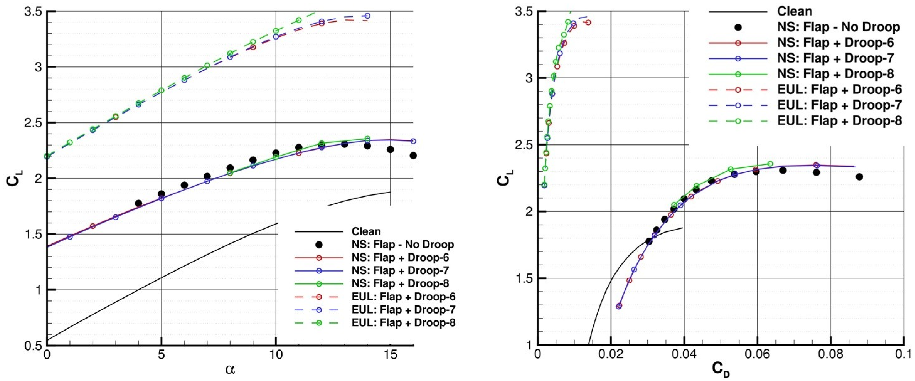
The droop nose is effective by increasing the stall incidence with the consequent increase in CL,MAX. At the same AoA, a small effect on CL can be detected from Figure 8. Target CL,MAX is obtained on the Flap 04 + Droop-8 (8°) configuration through Euler simulations, while RANS does not allow us to obtain target CL,MAX. Flow control needs to reduce/suppress the separation region.
Flow control as outflow BC with the two previous values of pressure distribution was performed by RANS, with suction applied at x/c ≈ 75% over 2% of the chord. On the droop nose configuration, target CL,MAX was obtained at AoA = 16° and with a local pressure distribution of 90 kPa (Figure 9).
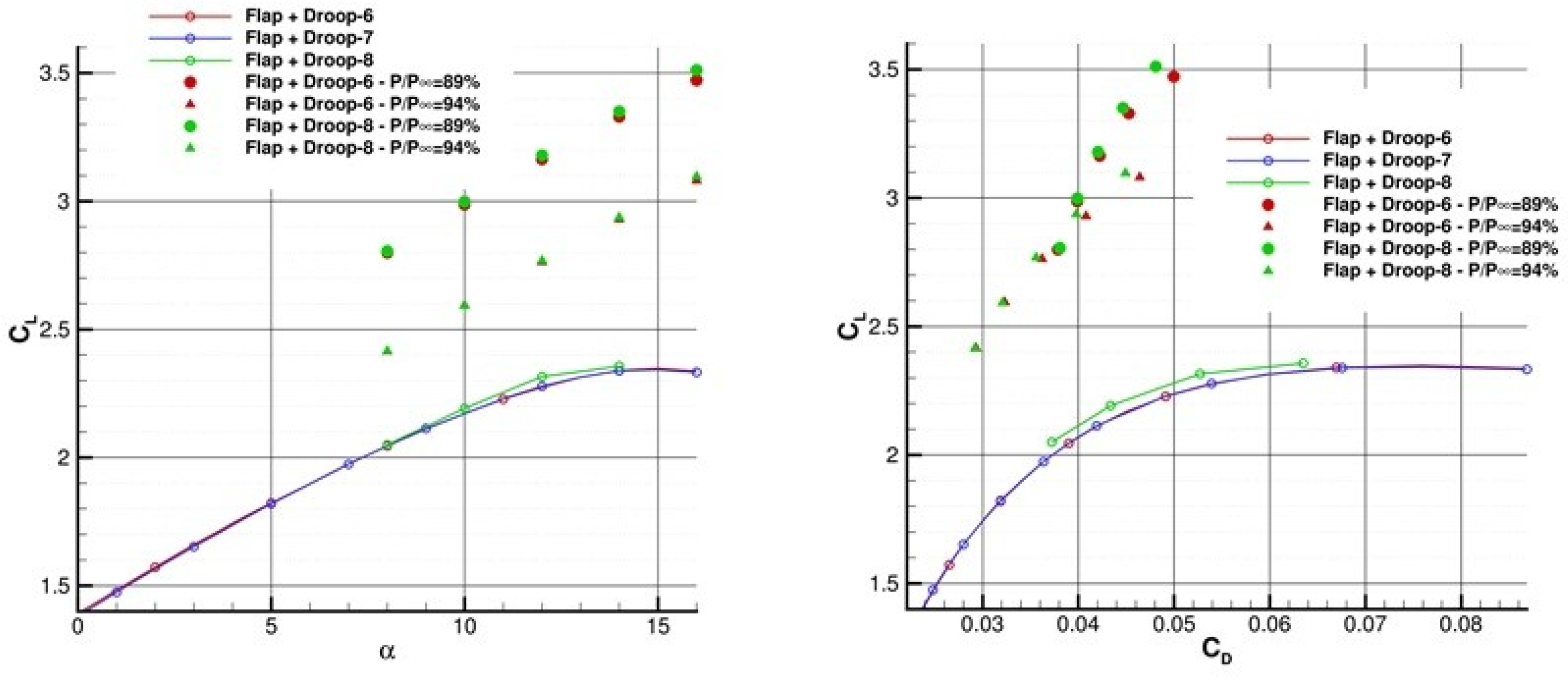
Another value of pressure distribution was added (98%). Due to the lack of convergence, some solutions are not present. While on the Flap 04 configuration, the activation of the flow control did not allow the requirement to be achieved (Figure 10, left); on Flap 04 + Droop-8, flow control was effective in achieving the landing requirement of CL,MAX = 3.5 at AoA = 16° and local pressure reduction P/P = 89%, which provided an attached flow to Xsep ≈ 90% of the chord (Figure 10, right). This led us to establish, as the first issue, the requirement that the flow control system should have to comply with the above-mentioned requirement in order for it to be effective in reducing the separation region and in order to guarantee the performance predicted for the landing phase.
Optimization of the suction parameters was performed. The objective was fixed as a request for reduction in the mass flow (MF) needed to control the separation on the flap, using the three previous local pressure distribution values. The results established a reduction of 16% in MF and a reduction in the region of application of the suction to 1.6% of the chord but with an increase in the x-coordinate of 5% of the chord. The required bi-dimensional CL,MAX was achieved with MF reduction by a local pressure distribution of P/P = 89% (Figure 11). The possibility of achieving values of CL that are also greater than 3.5 with lower mass flow was hypothesized.
From the suggestion of the pulsed blowing flow control system designed by TUD, some 2D RANS steady simulations were performed to estimate the effect only on the mass flow required. The active flow control system performed continuous blowing by simulating an inflow BC in the SU2 solver. Blowing was applied at x/c = 0.66%, with a jet momentum coefficient of Cµ = 0.04 (which is a reasonable value for landing), and by placing a step of height of 0.76% of the chord, upstream the flap shoulder. Target CL,MAX = 3.5 was obtained at AoA = 14° (Figure 12).
Comparing the flow field at AoA = 16° in Figure 13, it is possible to deduce that if the flow control is active, the separation is completely suppressed by blowing (right). The flow control system in the form of continuous blowing establishes the requirement that the flap plus droop configuration should have to comply with the jet momentum coefficient Cµ = 0.04 at AoA = 14° in order to be effective in reducing the separation region and in guaranteeing the performance prescribed for the landing phase.

4. Conclusions

The activities performed by CIRA in the framework of the HERWINGT project had the aim of designing an innovative wing suitable for future hybrid electric regional aircraft, which will contribute to the reduction in fuel burn and emissions. The present work contributes to the aerodynamic design of a wing’s high-lift system in the form of a compliant morphing flap. A morphing flap was designed through a CIRA in-house-developed evolutionary optimization software employing the SU2 open source RANS flow solver. The analysis conducted for the 2D wing section highlighted the finding that the required performances (the most demanding ones are for landing phase) can be achieved by the configuration equipped with both flap and droop nose, with active flow control applied to mitigate the separation occurring over the rear upper region of the wing section. The droop nose is effective in increasing stall incidence and, as a consequence, CL,MAX. The flow control was simulated by 2D steady RANS, both as suction and continuous blowing. Requirements were formulated in terms of mass flow and maximum extension of the separated region for the flow control system applied to the flap plus droop nose configuration. Suction provides flow attached to x/c = 90% at AoA = 16°; blowing provides flow attached to Cµ = 0.04 on the flap at AoA = 14°.

Author Contributions

Conceptualization, F.A.D., P.C., D.Q. and M.M.; methodology, D.Q.; formal analysis, F.A.D., P.C. and M.M.; validation, F.A.D., P.C. and M.M.; investigation, F.A.D., P.C. and M.M.; data curation, F.A.D., D.Q., P.C. and M.M; writing—original draft preparation F.A.D.; writing—review and editing, P.C., D.Q. and M.M; supervision, P.C. and D.Q.; project administration, P.C. All authors have read and agreed to the published version of the manuscript.

Funding

This research was funded by Clean Aviation Joint Undertaking under the European Union’s Horizon Europe research and innovation program under grant agreement ID 101102010.

Institutional Review Board Statement

Not applicable.

Informed Consent Statement

Not applicable.

Data Availability Statement

Data are contained within the article.

Acknowledgments

This study is part of the Hybrid Electric Regional Wing Integration Novel Green Technologies project (HERWINGT). This project has received funding from the Clean Aviation Joint Undertaking under the European Union’s Horizon Europe research and innovation program under grant agreement ID 101102010. The views and opinions expressed are, however, those of the author(s) only and do not necessarily reflect those of the European Union or the Clean Aviation Joint Undertaking. Neither the European Union nor the granting authority can be held responsible for them.

Conflicts of Interest

The authors declare no conflicts of interest.

References

  1. Catalano, P.; Diodati, G.; Lucariello, D.; Vitagliano, P. Aero-structural design on a high-aspect ratio wing. In Proceedings of the AIAA Aviation Forum, Las Vegas, NV, USA, 29 July–2 August 2024. [Google Scholar]
  2. Chen, H.; Chen, S.; Matthaeus, W.H. Recovery of the Navier-Stokes equations using a lattice-gas Boltzmann method. Phys. Rev. A 1992, 45, R5339–R5342. [Google Scholar] [CrossRef] [PubMed]
  3. Chen, H.; Orszag, S.A.; Staroselsky, I.; Succi, S. Expanded analogy between Boltzmann kinetic theory of fluids and turbulence. J. Fluid Mech. 2004, 519, 301–314. [Google Scholar] [CrossRef]
  4. Teixeira, C. Incorporating Turbulence Models into the Lattice Boltzmann Method. Int. J. Mod. Phys. 1998, 9, 1159–1175. [Google Scholar] [CrossRef]
  5. Quagliarella, D. Aerodynamic Shape Design Using Evolutionary Computation: A Tutorial with Examples and Case Studies. In Computational Intelligence in Aerospace Sciences; American Institute of Aeronautics and Astronautics (AIAA): Reston, VA, USA, 2014; pp. 529–581. [Google Scholar]
  6. Economon, T.D.; Palacios, F.; Copeland, S.R.; Lukaczyk, T.W.; Alonso, J.J. SU2: An Open-Source Suite for Multiphysics Simulation and Design. AIAA J. 2016, 53, 828–846. [Google Scholar] [CrossRef]
  7. Hansen, N. The CMA evolution strategy: A comparing review. In Towards a New Evolutionary Computation: Advances in the Estimation of Distribution Algorithms; Lozano, J.A., Larrañaga, P., Inza, I., Bengoetxea, E., Eds.; Springer: Berlin/Heidelberg, Germany, 2006; pp. 75–102. ISBN 978-3-540-32494-2. [Google Scholar]
  8. Hansen, N. The CMA Evolution Strategy: A Tutorial. arXiv 2016, arXiv:1604.00772. [Google Scholar]
  9. Radespiel, R.; Burnazzi, M.; Casper, M.; Scholz, P. Active Flow Control for High Lift with Steady Blowing. Aeronaut. J. 2015, 120, 171–200. [Google Scholar] [CrossRef]
  10. Haucke, F.; Nitsche, W. Active flow control on the flap of a 2D high-lift wing section towards high Reynolds number application. In Proceedings of the 31st AIAA Applied Aerodynamics Conference, San Diego, CA, USA, 24–27 June 2013; AIAA: Reston, VA, USA, 2013. [Google Scholar]
  11. Ekaterinaris, J.A. Prediction of active flow control performance on airfoils and wings. Aerosp. Sci. Technol. 2004, 8, 401–410. [Google Scholar] [CrossRef]
  12. Holl, T.; vel Job, A.K.; Giacopinelli, P.; Thiele, F. Numerical study of active flow control on a high-lift configuration. J. Aircr. 2012, 49, 1406–1422. [Google Scholar] [CrossRef]
  13. Goffert, B.; Silva, R.G.; Francisco, C.P.F.; Reis, M.L.C.C. Numerical Study of Flow Control on Simplified High-Lift Configurations. J. Appl. Fluid Mech. 2023, 16, 634–654. [Google Scholar]
Figure 1. Optimization chain.
Engproc 90 00013 g001
Figure 2. Left: representation of the clean airfoil (black curve) and the preliminary morphing flap configuration (red curve). Right: comparison between the lift coefficient curves of the clean airfoil (black) and the preliminary morphing flap configuration (red).
Engproc 90 00013 g002
Figure 3. Depiction of the five optimized configurations from 00 to 04.
Engproc 90 00013 g003
Figure 4. Lift coefficient curves (left) and polar curves (rights) for the five optimized configurations.
Engproc 90 00013 g004
Figure 5. Lift coefficient curves (left) and polar curves (right), by RANS, Euler, and potential simulations, for Flap 04 configuration with and without active flow control.
Engproc 90 00013 g005
Figure 6. Pressure coefficient cp contours plus streamlines of Flap 04, at AoA = 12°, in the cases of no control applied (left), local pressure distribution P/P = 89% (center), and P/P = 94% (right).
Engproc 90 00013 g006
Figure 7. Depiction of the droop nose provided by POLIMI at the three deflections of 6°, 7°, 8° added to Flap 04.
Engproc 90 00013 g007
Figure 8. Lift coefficient curves (left) and polar curves (right), by RANS and Euler simulations, for the Flap 04 plus droop nose configurations.
Engproc 90 00013 g008
Figure 9. Lift coefficient curves (left) and polar curves (right) by RANS for the Flap 04 plus droop nose configurations with and without active flow control.
Engproc 90 00013 g009
Figure 10. Requirements for the flow control system: Flap 04 (left); Flap 04 + Droop-8 (right).
Engproc 90 00013 g010
Figure 11. Lift coefficient curves obtained through RANS for the Flap 04 plus droop nose configurations without flow control. The green symbols are the results for the Flap 04 + Droop-8 configuration with flow control. The orange symbols are the results for the mass flow parameter optimization results.
Engproc 90 00013 g011
Figure 12. Depiction of the Flap 04 + Droop-8 configuration with the step upstream the flap shoulder (left). Lift coefficient CL curves of the Flap 04 + Droop-8 configuration, no control applied, performed by RANS and Euler simulations. The Flap 04 + Droop-8 configuration with continuous blowing applied, performed by RANS simulations.
Engproc 90 00013 g012
Figure 13. Mach number contours plus streamlines of the Flap 04 + Droop-8 configuration (zoom of the flap region), at AoA = 16°, in the cases of no control applied (left) and continuous blowing applied (right).
Engproc 90 00013 g013
Disclaimer/Publisher’s Note: The statements, opinions and data contained in all publications are solely those of the individual author(s) and contributor(s) and not of MDPI and/or the editor(s). MDPI and/or the editor(s) disclaim responsibility for any injury to people or property resulting from any ideas, methods, instructions or products referred to in the content.

