Abstract
The present paper illustrates the design space exploration of a supersonic mixed-flow turbofan engine for civil applications. The aircraft platform selected is a 10-passenger business jet, cruising at Mach 1.6. To overcome noise limitations at take-off, an alternative engine architecture with additional exhaust nozzle variability, to overcome the take-off noise limit, is proposed. The fully variable area nozzle configuration allows for an overall 15% weight reduction against a partially variable area nozzle architecture. In terms of overall aircraft mission fuel burn, it shows an 8% mission fuel burn reduction against the partially variable area nozzle architecture, with a final fuel efficiency of 11.4 pax-mile/us gallon.
1. Introduction
In recent decades, the interest in civil supersonic flight has resurged thanks to the efforts of several key players from industry and academia. Several projects were launched to investigate civil supersonic flight in a global effort that has brought the world back to the verge of the next civil supersonic transport era [1,2,3,4]. Understanding the environmental impact of next generation supersonic aviation is of primary importance to allow regulatory boards to establish new regulations and certification processes, as the only available data for supersonic civil aircraft pertain to the Concorde era. To support this research, the EU funded the SENECA Project [5] (“LTO Noise and Emissions of Supersonic Aircraft”), in which the present work falls.
Several requirements constrain the engine cycle design for supersonic applications. As per their subsonic counterparts, they must meet aircraft performance requirements at all flight conditions while adhering to the aircraft’s geometric constraints. Furthermore, for civil supersonic engines to be perceived as viable, the engine cycle design should not only aim for fuel efficiency but also for compliance with today’s, and future, aviation noise and emission goals, both during supersonic flight (sonic boom) and around the airport vicinity (landing and take-off cycle, LTO).
Because of their reduced noise signature, the preferred choice for civil supersonic engine architectures is a mixed flow turbofan. Recent studies have focused on low BPRs (~1.5–3) [6,7], as they offer the best performance for landing and take-off (LTO) noise requirements, while minimizing engine size and weight.
This present work shows the impact of engine cycle design and architecture on aircraft performance. Two engine configurations are proposed, namely a two-spool mixed flow turbofan engine (MFTF) with a fixed throat and variable exit area nozzle and a mixed-flow turbofan equipped with of a fully variable (throat and exit) area nozzle (VA). The impact on aircraft performance is assessed in terms of mission fuel burn and passenger-mile/gallon. Although a variable area nozzle was implemented on Concorde for noise abatement purposes, and others mention this as a possible architecture [8], in several recent studies this has not been implemented as a noise abatement device but rather as a fan-working line control system [1]. The authors highlight that the main assumption underlying this study is considering supersonic operations taking place exclusively when flying over water, while the aircraft flies subsonic over land. Consequently, noise-related restrictions during the landing and take-off (LTO) cycle assume a predominant importance for this study, while noise limitations at high altitude operations, such as those caused by sonic booms, are considered outside the scope of this research.
2. Methods
The Aeolus E-19 is a 10-passenger business jet, designed for a flight range of 4000 nm with a Mach 1.6 cruise speed [9]. Six main flight segments, namely take-off, subsonic climb, transonic acceleration, supersonic climb, supersonic cruise, and descent, characterize the baseline mission profile. The aircraft performs a rapid initial climb to reach the 10,000 m mark, avoiding subsonic traffic, and then performs a transonic acceleration from Mach 0.95 to 1.3. Subsequently, it climbs supersonically while accelerating to Mach 1.6, and then it climb-cruises with a constant Mach number.
A simplified block diagram for the engine
performance model is illustrated in Figure 1. Black lines represent the mechanical power connections while blue lines
represent flow connections, with directions. For lifting considerations, supersonic mid-cruise (SMCr) is considered the turbine cooling flow sizing point. Additional cooling, ~1% of the high-pressure compressor (HPC) inlet
flow, is considered for disk cooling and purging [10]. Engine technology levels are based on public domain data for a 2025–2035
entry-into-service.
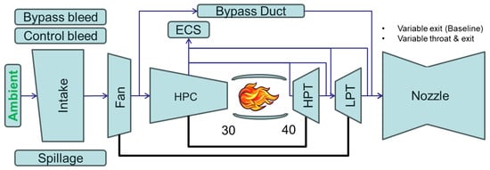
Figure 1.
Engine block diagram.
The design-limiting temperatures of 850 K, 1750 K, and 1650 K have been selected for the HPC delivery (T30), high-pressure turbine (HPT) nozzle guide vanes (NGV) inlet (T40) and HPT rotor inlet temperature (T41), respectively. Turbine blade metal temperature limits are selected to represent cooled nickel-based super alloy blades with thermal barrier coatings. These are set to 1170 K and 1070 K for the HPT and the low-pressure turbine (LPT), respectively. At the design point, 0.85 mixing efficiency (ηmix) is considered at the mixer, along with a 0.45 mixer outlet Mach number (M64). The extraction ratio (ER), defined as the total pressure ratio at the mixer inlet, is assumed to be unitary. The combustion efficiency (ηcomb) is set to 0.9999. To constrain the design to jet velocities that could be compliant with noise limitations in the LTO cycle, a limiting exhaust Mach number of 0.95 is considered. Fan and HPC polytropic efficiencies (ηpol), with HPT and LPT isentropic efficiencies (ηis) are shown in Table 1, which provides a complete overview of the engine design limits and inputs.

Table 1.
Engine design technology assumptions.
The installed performance of the engine is assessed within an integrated framework that combines the Numerical Propulsion System Simulation (NPSS [11,12]), and the Performance of Installed Propulsion Systems Interactive (PIPSI) methodology [13], which accounts for the installation effects of the supersonic intake and exhaust systems. For the engine cycle design, a multi-point design approach is used. This involves five key operating points, namely, the SMCr, supersonic top of climb (STOC), end and beginning of transonic acceleration (ETR and BTR), and maximum take-off (MTO). Table 2 offers a summary of the main installed thrust requirements for this engine cycle design. The installed net thrust accounts for the engine gross thrust and momentum drag, intake- and afterbody-related drags, and the aircraft power off-take and air requirements.
Table 2.
E19—engine thrust requirements.
Engine weight assessment is performed in ATLAS [13], a Cranfield in-house weight and size estimation tool that adopts a component-based approach to size the engine turbomachinery. This has been extensively used in the past in several research projects and offers a good estimation (with an error of less than 5%) of the engine weight. The aircraft performance is modeled in NASA FLOPS.
3. Results
3.1. Engine Cycle Design
Figure 2 illustrates the MFTF engine preliminary design space exploration in terms of installed SMCr specific fuel consumption (SFC) , fan diameter and nozzle throat Mach number at MTO. The SFC curve follows a parabolic trend, reaching a minimum between 200 and 220 N/kg/s of SMCr specific net thrust (SpFn). The fan diameter, which is sized at the maximum flow capacity point, reduces progressively from 1.55 to 0.9 m across the design space. For engine designs with SpFn at SMCr higher than 210 N/kg/s, the nozzle is choked at MTO. Appling the limitation of LTO noise, the design space is limited to a SMCr SpFn of 186 N/kg/s, with a fan size of 1.35 m.
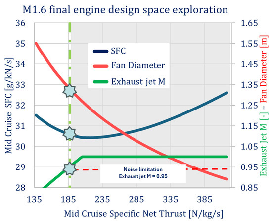
Figure 2.
MFTF design space exploration.
Aircraft performance is a combination of several
parameters that include engine and nacelle weight, drag distribution, and
engine efficiency. Thus, aiming for a higher SpFn than the one achieved with
the MFTF ( ) configuration is necessary
for improving this aspect. A fully variable throat and exit area (VA,
) configuration is necessary
for improving this aspect. A fully variable throat and exit area (VA,  ) nozzle is considered, to
allow the unchoking of the exhaust flow at MTO and meet the noise requirements,
while increasing the engine SpFn level. This feature enables nozzle pressure
ratio (NPR) reduction for take-off, to ensure a subsonic exhaust flow velocity.
At take-off, the engine behavior is dictated by the critical NPR, which sets
the required engine mass flow for this condition.
) nozzle is considered, to
allow the unchoking of the exhaust flow at MTO and meet the noise requirements,
while increasing the engine SpFn level. This feature enables nozzle pressure
ratio (NPR) reduction for take-off, to ensure a subsonic exhaust flow velocity.
At take-off, the engine behavior is dictated by the critical NPR, which sets
the required engine mass flow for this condition.
) configuration is necessary
for improving this aspect. A fully variable throat and exit area (VA, ) nozzle is considered, to
allow the unchoking of the exhaust flow at MTO and meet the noise requirements,
while increasing the engine SpFn level. This feature enables nozzle pressure
ratio (NPR) reduction for take-off, to ensure a subsonic exhaust flow velocity.
At take-off, the engine behavior is dictated by the critical NPR, which sets
the required engine mass flow for this condition.For the same noise limitation at take-off, applying the VA configuration increases the engine SpFn by ~24%, corresponding to an overall 8% fan diameter and ~0.6% SFC reduction, respectively, as shown in Figure 3. Overall, this correlates to a 15.6% reduction in weight, as illustrated in Figure 4 which shows the weight assessment for both cycles.
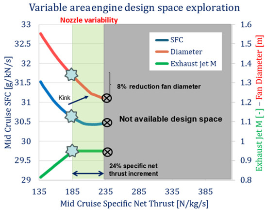
Figure 3.
VA design space exploration.
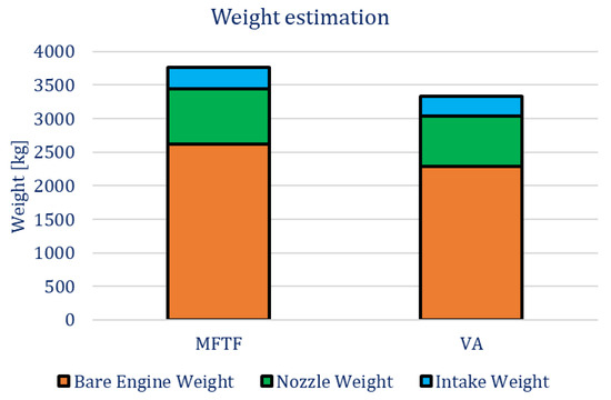
Figure 4.
Engine weight estimation.
After a SpFn of 214 N/kg/s, the fan sizing point switches from ETR to MTO, causing the kink point in the SFC curve. This is due to the increased MTO corrected mass flow. Further details on this, as well as the thermodynamic aspects regarding these two cycles, are offered in [14].
3.2. Aircraft Performance
Each engine in the design space exploration above has been integrated into the baseline aircraft model and the aircraft performance has been estimated in the form of the mission fuel burn (MFB) at a fixed range of 4000 nm and flight profile. The MFB provides valuable means to understand the trade-offs between engine efficiency and overall size and drag. Figure 5 below shows the MFB assessment as a function of engine SMCR SpFn. As the engine SMCR SpFn increases, the MFB decreases proportionally, approaching the overall MFB minimum. For the MFTF configuration, the optimum design (Star) reaches an overall MFB of ~16,100 kg. The alternative architecture of VA allows the MFB to be reduced by 9%, reaching ~14,700 kg. Table 3 below summarizes the aircraft mission performance for the optimum designs of the two configurations. In transportation, vehicle fuel efficiency is often described in terms of PAX-mile/US gal (in the US). It represents the distance that one passenger can travel on one US gallon of fuel for a particular type of transport, and it is considered as the figure of merit (FOM) in this study. The results show that the FOM improves by 12% with the VA configuration.
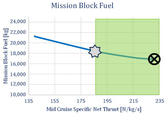
Figure 5.
Design space exploration—Mission Fuel Burn.
Table 3.
Aircraft mission performance.
Figure 6 below shows a useful PAX-mile/US gallon comparison between the VA engine and the Gulfstream G550, a subsonic business jet flying a comparable distance for a maximum of 20 passengers, Concorde, and the Airbus A350. The reference Concorde value is obtained from [14], while Gulfstream FOM is calculated from the referenced overall MFB and the reference mission distance, assuming the maximum number of passengers. As expected, the VA FOM is low compared to current subsonic business jets and to Concorde. FOM is influenced by several parameters including weight, drag, propulsive efficiency, range, operational profiles, and design speed. Business jets are usually less fuel efficient than airliners, with worse payload-to-weight ratios and operational profiles, due to their higher flight speeds and reduced lift-to-drag characteristics. Supersonic business jets exhibit these characteristics at an even higher degree.
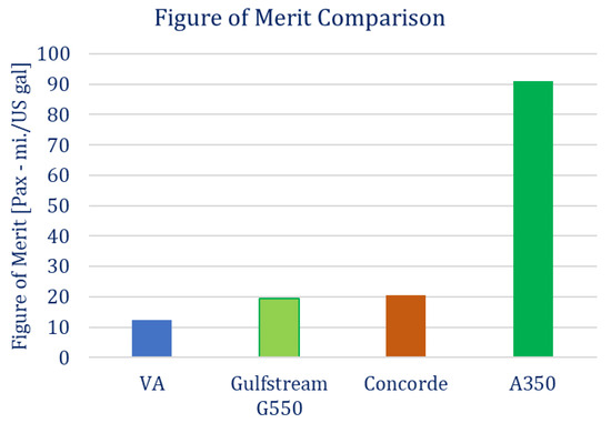
Figure 6.
Figure of merit comparison.
4. Conclusions
This paper illustrates the design space exploration of a supersonic business jet engine and the impact of the engine architecture on the aircraft performance. The case study proposed herein involves the Mach 1.6 SENECA business jet, designed to carry 10 passengers for a 4000 nm range mission. The engine cycle design is performed following a 5-design-point approach. The cycle design points are the key operating points across the mission envelope.
Two engine configurations are proposed, namely, a MFTF and a VA. For the MFTF engine, size and SFC are strongly limited by the LTO noise constraint. The optimum engine design for this configuration reaches an SFC of 30.6 g/kN/s for a SpFn of 186 N/kg/s at SMCR conditions. The VA architecture allows for increase in SpFn by ~24% with an SFC of 30.4 g/kN/s at SMCR conditions. The resulting powerplant fan diameter is reduced compared to the MFTF, from 1.35 to 1.22 m. Consequently, the weight is reduced by 15%, reaching an overall weight of 5 tonnes for the VA architecture.
The impact of engine size, weight, and SFC on aircraft performance is assessed herein. For a 4000 nm range and a fixed aircraft platform, the increased engine SpFn of the VA architecture corresponds to an 8% reduction in mission fuel burn (from 16,100 kg for MFTF to 14,700 kg for VA). Aircraft fuel efficiency is evaluated in terms of PAX-mil/gal. The VA architecture presented with 11.4 PAX-mil/US gal, compared to the 10.2 PAX-mil/US gal of the MFTF, offering a 12% reduction.
Author Contributions
Investigation, D.D.G., S.A., C.M. and S.B.; writing—original draft preparation, D.D.G.; writing—review and editing, D.D.G., C.M. and S.B.; supervision, C.M. and S.B.; project administration, C.M.; funding acquisition, C.M. All authors have read and agreed to the published version of the manuscript.
Funding
This research was funded by the SENECA project under the European Union’s Horizon 2020 research and innovation program, grant agreement No. 101006742.
Institutional Review Board Statement
Not applicable.
Informed Consent Statement
Not applicable.
Data Availability Statement
Data are contained within the article.
Conflicts of Interest
The authors declare no conflicts of interest.
References
- Wedge, H.R.; Bonet, J.; Magee, T.; Chen, D.; Hollowell, S.; Kutzmann, A.; Mortlock, A.; Stengle, J.; Nelson, C.; Adamson, E.; et al. (Boeing N+2) Supersonic Concept Development and Systems Integration; NASA/CR-2010-216842; NASA: Washington, DC, USA, 2010; p. 216842.
- Wedge, H.R.; Bonet, J.; Magee, T.; Tompkins, D. N+3 Advanced Concept Studies for Supersonic Commercial Transport Aircraft Entering Service in the 2030–2035 Period; NASA: Washington, DC, USA, 2011; p. 129.
- Westmoreland, J.S.; Stern, A.M. Variable Cycle Engine Technology Program; NASA: Washington, DC, USA, 1978.
- Hoffman, S. Bibliography of Supersonic Cruise Research (SCR) Program from 1977 to Mid-1980; NASA Reference Publication 1063 Bibliography of Supersonic Cruise Research (SCR) Program From 1977 to Mid-1980; NASA: Washington, DC, USA, 2020.
- DLR. SENECA-(LTO) noiSe and EmissioNs of supErsoniC Aircraft. Available online: https://seneca-project.eu/ (accessed on 29 November 2024).
- Conners, T.R.; Howe, D.C. Impact of Engine Cycle Selection on Propulsion System Integration and Vehicle Performance for a Quiet Supersonic Aircraft. In Proceedings of the 43rd AIAA Aerospace Sciences Meeting, Reno, NV, USA, 10–13 January 2005. [Google Scholar] [CrossRef]
- Berton, J.J.; Jones, S.M.; Seidel, J.A.; Huff, D.L. Noise predictions for a supersonic business jet using advanced take-off procedures. Aeronaut. J. 2018, 122, 556–571. [Google Scholar] [CrossRef]
- Whurr, J. Propulsion system concepts and technology requirements for quiet supersonic transports. Int. J. Aeroacoustics 2004, 3, 259–270. [Google Scholar] [CrossRef]
- Villena Munoz, C.; Lawson, C.; Riaz, A.; Jaron, R. Conceptual Design of Supersonic Aircraft to Investigate Environmental Impact. In Proceedings of the AIAA SCITECH 2024 Forum, Orlando, FL, USA, 8–12 January 2024. [Google Scholar] [CrossRef]
- Del Gatto, D.; Adamidis, S.; Mourouzidis, C.; Brown, S.; Pachidis, V. Design Space Exploration of Next-Generation Supersonic Business Jet Engine with a Focus on Landing and Take-off (LTO) Noise. In Proceedings of the 34th International Council of Aerospace Science, Florence, Italy, 9–13 September 2024. [Google Scholar]
- Hendricks, E.S. A Multi-Level Multi-Design Point Approach for Gas Turbine Cycle and Turbine Conceptual Design. Ph.D. Thesis, Georgia Institute of Technology, Atlanta, GA, USA, 2017. [Google Scholar]
- Benyo, T.L. Flow matching results of an MHD energy bypass system on a supersonic turbojet engine using the Numerical Propulsion System Simulation (NPSS) environment. In Proceedings of the 42nd AIAA Plasmadynamics and Lasers Conference, Honolulu, HI, USA, 27–30 June 2011. [Google Scholar] [CrossRef]
- Kowalski, E.J. Computer Code for Estimating Installed Performance of Aircraft Gas Turbine Engines. Volume 1: Final Report. Seattle, WA, USA, 1979. Available online: https://ntrs.nasa.gov/citations/19800004788 (accessed on 29 November 2024).
- Lolis, P. Development of a Preliminary Weight Estimation Method for Advanced Turbofan Engines. Ph.D. Thesis, Cranfield University, Bedford, UK, 2014; 214p. Available online: https://dspace.lib.cranfield.ac.uk/handle/1826/9244 (accessed on 29 November 2024).
Disclaimer/Publisher’s Note: The statements, opinions and data contained in all publications are solely those of the individual author(s) and contributor(s) and not of MDPI and/or the editor(s). MDPI and/or the editor(s) disclaim responsibility for any injury to people or property resulting from any ideas, methods, instructions or products referred to in the content. |
© 2025 by the authors. Licensee MDPI, Basel, Switzerland. This article is an open access article distributed under the terms and conditions of the Creative Commons Attribution (CC BY) license (https://creativecommons.org/licenses/by/4.0/).