Proceeding Paper

Winglet Design for Class I Mini UAV—Aerodynamic and Performance Optimization †

by
Eleftherios Nikolaou
*,
Eleftherios Karatzas
,
Spyridon Kilimtzidis
and
Vassilis Kostopoulos
Applied Mechanics Laboratory, Mechanical Engineering and Aeronautics Department, University of Patras, Rio Campus, 26500 Patras, Greece
*
Author to whom correspondence should be addressed.
Presented at the 14th EASN International Conference on “Innovation in Aviation & Space Towards Sustainability Today & Tomorrow”, Thessaloniki, Greece, 8–11 October 2024.
Eng. Proc. 2025, 90(1), 111; https://doi.org/10.3390/engproc2025090111
Published: 7 May 2025

Abstract

:
The aerodynamic performance of an aircraft can be enhanced by incorporating wingtip devices, or winglets, which primarily reduce lift-induced drag created by wingtip vortices. This study outlines an optimization procedure for implementing winglets on a Class I fixed-wing mini-UAV to maximize aerodynamic efficiency and performance. After the Conceptual and Preliminary design phases, a baseline UAV was developed without winglets, adhering to specific layout constraints (e.g., wingspan, length). Various winglet designs—plate and blended types with differing heights, cant angles, and sweep angles—were then created and assessed. A Computational Fluid Dynamics (CFD) analysis was conducted to evaluate the flow around both the winglet-free UAV and configurations with each winglet design. The simulations employed Reynolds-Averaged Navier-Stokes (RANS) equations coupled with the Spalart-Allmaras turbulence model, targeting the optimal winglet configuration for enhanced aerodynamic characteristics during cruise. Charts of lift, drag, pitching moment coefficients, and lift-to-drag ratios are presented, alongside flow contours illustrating vortex characteristics for both baseline and optimized configurations. Additionally, dynamic stability analyses examined how winglets impact the UAV’s stability and control. The results demonstrated a significant improvement in aerodynamic coefficients ( C L m a x , L / D m a x , C L a , C m a ), leading to an increase in both range and endurance.

1. Introduction

Optimizing aerodynamic performance is a crucial area in aeronautical engineering, whether for an aircraft in the design phase or one already in operation that requires enhancements. Effective aerodynamic optimization can yield significant benefits, such as extending mission range, increasing flight duration, reducing fuel or battery consumption (for electric-powered aircraft), and boosting payload capacity. One way to achieve the aerodynamic performance optimization of an aircraft is the proper design of the wing tip. Wingtip designs come in many shapes and sizes and contribute to drag at least in three ways [1]:
  • Winglets influence the wetted area, thereby impacting viscous drag.
  • They alter the wingtip vortex, similarly to the effects of increasing aspect ratio.
  • They adjust the spanwise pressure distribution and can be designed to delay the onset of wave drag.
A brief description of the positive and negative aspects of each wingtip design is given in [2]. Thus, a well-designed wingtip can minimize or even avoid tip vortices resulting in increased lift and reduced induced drag. The most advanced wingtip device is the winglet. The winglet was first invested by Richard Whitcomb in the early 1970s [3], and his research showed that the winglet on a Boeing KC-135 tanker aircraft increased its cruise range by as much as 7%. His work encourages many manufacturers of commercial, business, and General Aviation (GA) aircraft to incorporate winglets on their design. Many modern airliners feature blended winglets, a design distinct from the Whitcomb winglet, patended by Louis B. Gratzer as US Patent 5,348,253 [4].
Over the past decades, significant research has been dedicated to winglet design for optimizing aircraft performance. Panagiotou et al. [5] introduced a winglet optimization procedure for a Medium-Altitude-Long-Endurance (MALE) UAV, employing Computational Fluid Dynamics (CFD) to enhance aerodynamic efficiency. Similarly, Liang Zhang et al. [6] studied the optimization of winglet configurations to improve the cruising efficiency of solar-powered aircraft. J. P. Eguea et al. [7] analyzed the aerodynamic effects of camber morphing winglets on a midsize business jet, utilizing both medium-fidelity (BLWF code) and high-fidelity (CFD) methods. Furthermore, Yahona et al. [8] examined the influence of various geometric parameters of blended winglets on the aerodynamic performance of the NXXX aircraft using CFD analysis.
This study aims to investigate various wingtip devices to identify the most effective option for maximizing a UAV’s range and endurance during the cruise phase. It also includes stability and control analyses to ensure a balanced design, thus broadening the scope of existing research by encompassing both aerodynamic efficiency and dynamic stability. According to J. Roskam’s findings across multiple studies, the effectiveness of a wingtip device is highly dependent on the specific mission and aircraft configuration [9]. Consequently, the results of this research apply exclusively to the cruise phase of this UAV. All winglet configurations were evaluated on a Class I mini-UAV with a cut-off wingtip, which was designed by the Applied Mechanics Laboratory of the University of Patras. This study evaluated the aerodynamic performance of the initial UAV configuration incorporating nineteen different winglet designs, including plate winglets (endplates), and blended winglets via high-fidelity CFD simulations. The most efficient configuration was then assessed for stability and control characteristics and compared with those of the UAV featuring a cut-off wingtip.

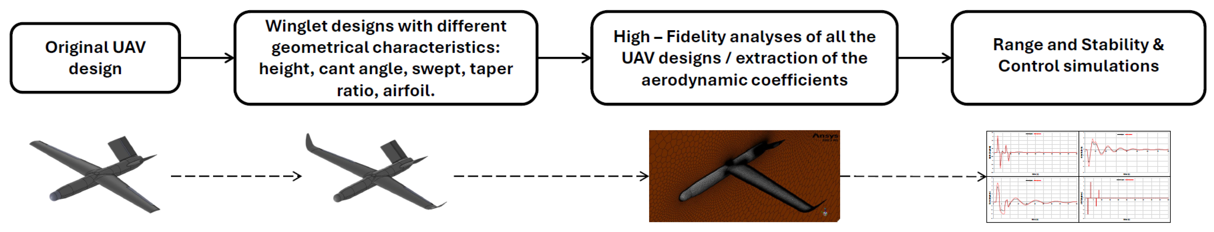
2. Materials and Methods

2.1. Original Aircraft’s Characteristics

The first step is to formulate the characteristics of the aircraft that will be examined. The design characteristics were derived from an aircraft designed by the Applied Mechanics Laboratory of the University of Patras, as mentioned in the Introduction. According to NATO’s categorization system for UAVs, this aircraft is categorized as a Class I Mini UAS. Table 1 presents key UAV parameters required for this study.

2.2. Winglet Design Methodology

The winglet design methodology falls within the Preliminary Design phase of an aircraft. Beginning with the aircraft’s external surface as illustrated in the flowchart below (Figure 1), several winglet configurations were created for a cut-off wingtip, each varying in specific geometric characteristics: height (h), cant angle ( ϕ ), sweep, taper ratio, and the airfoil profile at the root and tip. Each UAV configuration with a different winglet was then simulated during the cruise phase using high-fidelity aerodynamic analysis to determine and compare aerodynamic coefficients against the original UAV design. This enabled an analysis of range and endurance to identify the optimal winglet design for cruise performance. Additionally, the effect of the optimal winglet on the UAV’s stability and control characteristics was investigated.

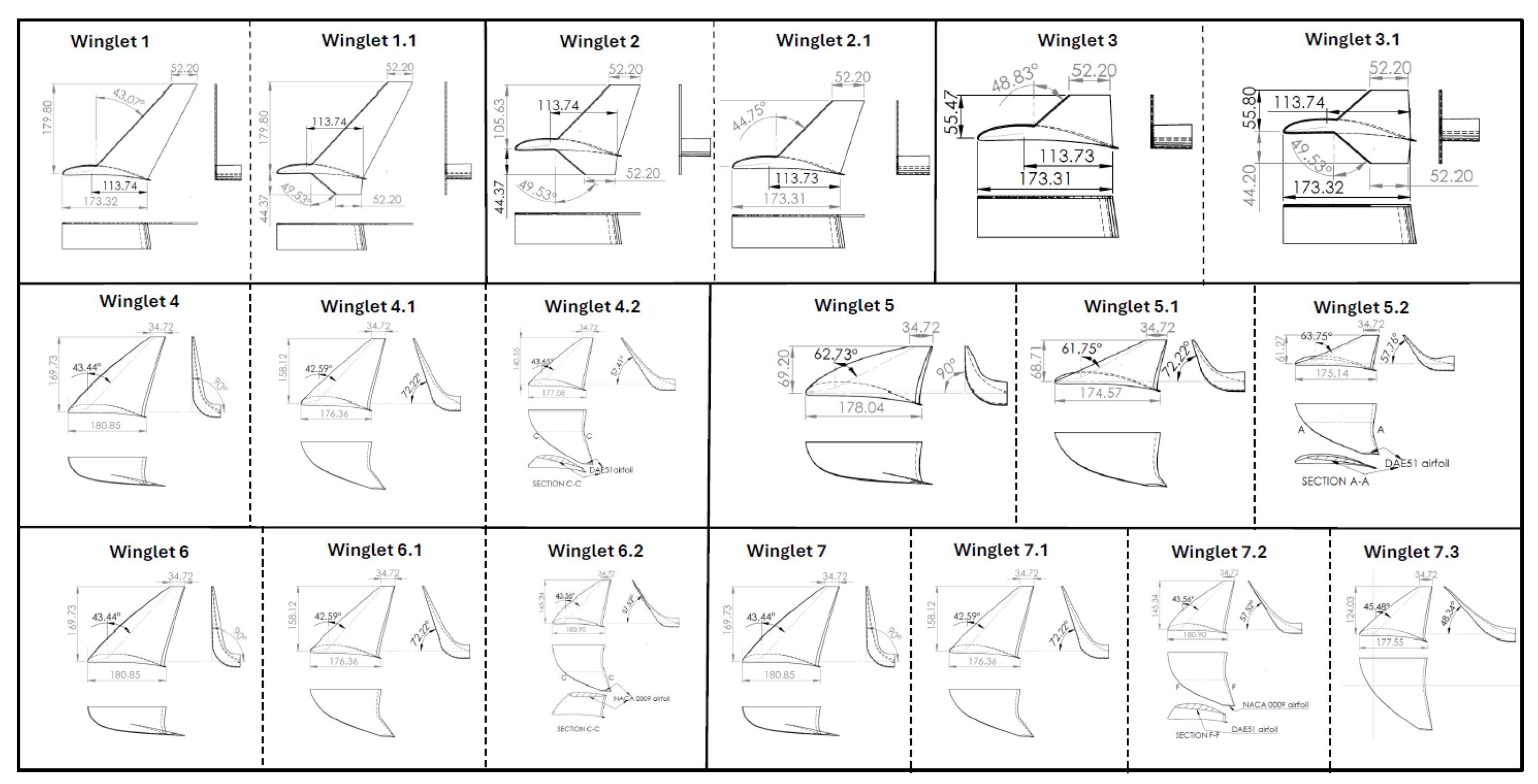
2.3. Winglet Configurations

The design of each winglet with their geometrical characteristics are shown in Figure 2.

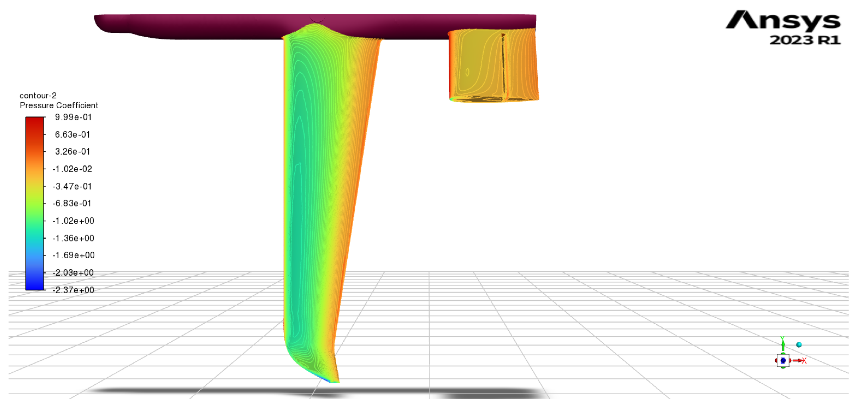
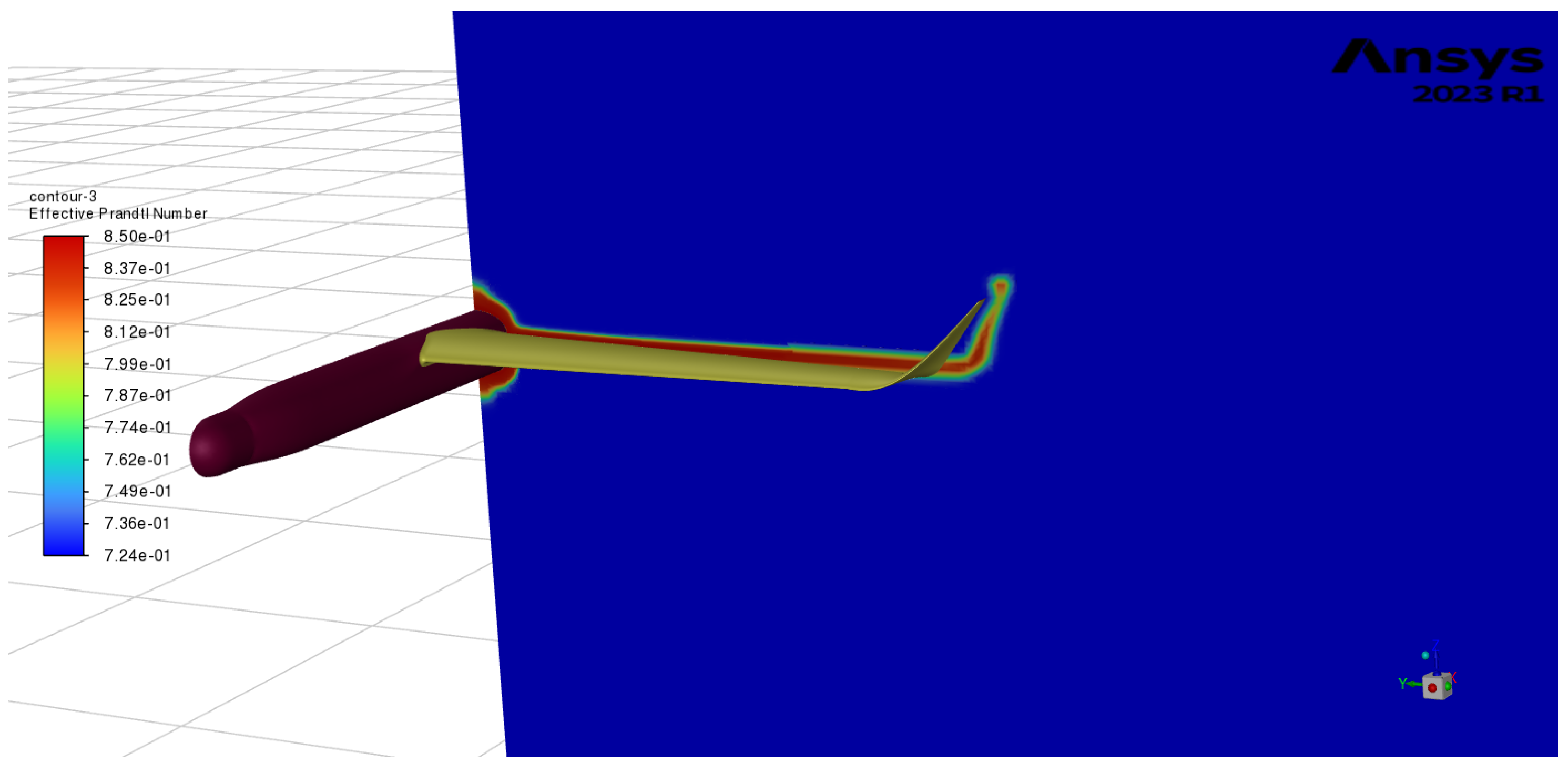
2.4. Computational Fluid Dynamics (CFD)

A full-scale (1:1) UAV model was designed for each configuration and analyzed using Computational Fluid Dynamics (CFD) to compare their aerodynamic performance with baseline results. The computational domain dimensions and boundary conditions were tailored to reflect the UAV’s operational environment and altitude. Simulations were conducted using ANSYS Fluent (https://www.ansys.com/products/fluids/ansys-fluent/ansys-fluent-trial, accessed on 1 March 2025), employing the Reynolds-Averaged Navier-Stokes (RANS) equations, coupled with the Spalart-Allmaras turbulence model. The computational domain dimensions for the UAV model were 10.0 × 5.0 × 25.0 m. The Navier-Stokes equations were discretized using the Finite Volume Method (FVM) and solved in terms of RANS equations, assuming incompressible flow and steady-state conditions, with an appropriately refined mesh. The first cell wall distance was calculated and set to target a Y + value of approximately 1, ensuring accurate resolution of the boundary layer evolution. A mesh independence study was conducted to confirm that mesh refinement did not influence the solution, identifying the optimal mesh size for computational efficiency. Pressure and temperature values were calculated based on the UAV’s maximum operational altitude and applied to the computational domain. The inlet velocity was set to 23.7 m/s (cruise velocity), with a corresponding Reynolds number of 3.86 10 5 , based on the UAV’s mean aerodynamic chord (MAC). Outlet conditions were applied with no pressure gradient difference, and turbulence intensity and length scale were specified as 3.7% and 0.7 m, respectively, corresponding to the UAV’s length and operating Reynolds number. Additionally, a symmetry boundary condition was imposed along the longitudinal plane to reduce computational costs while maintaining solution accuracy.

3. Results

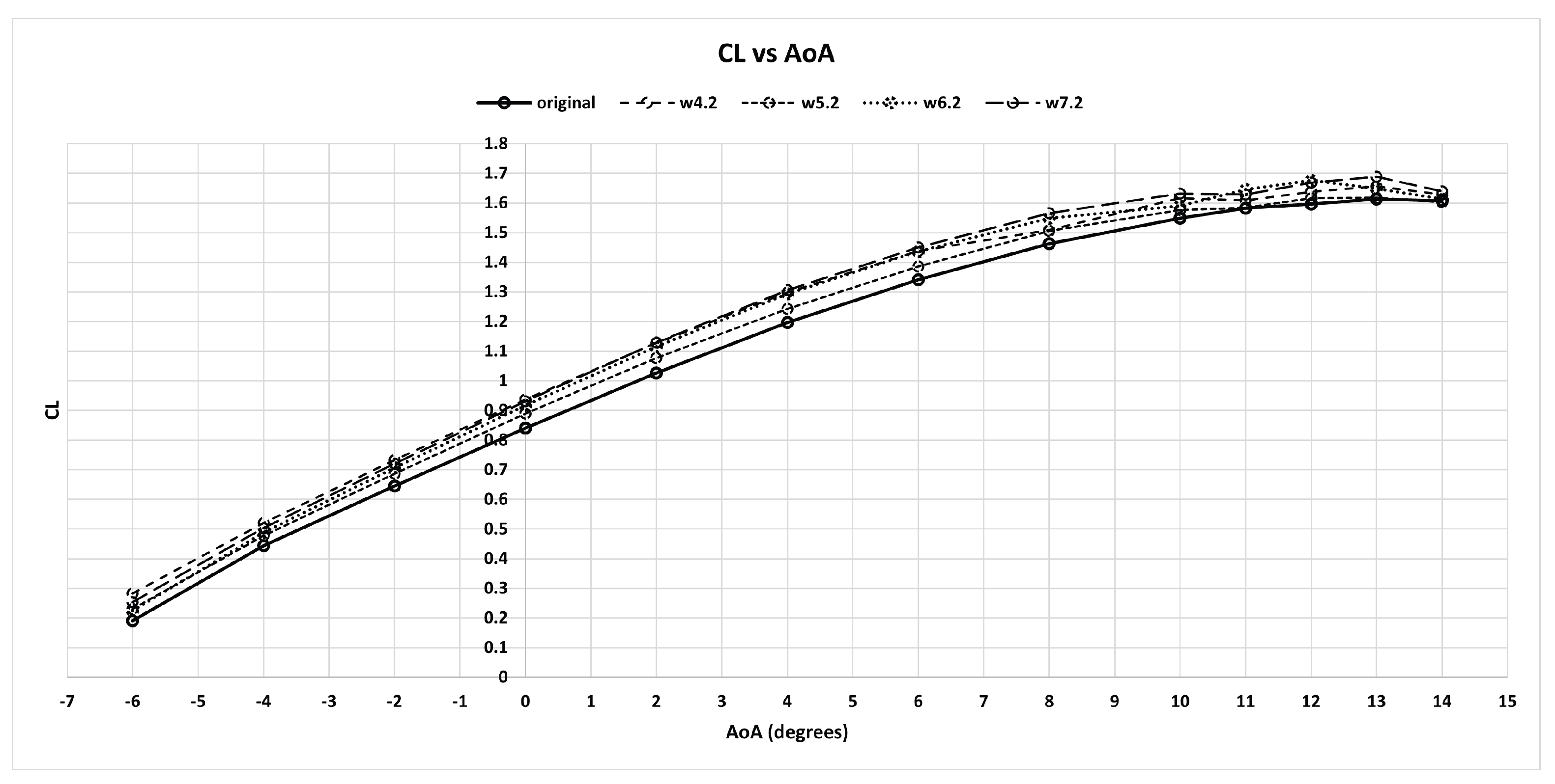
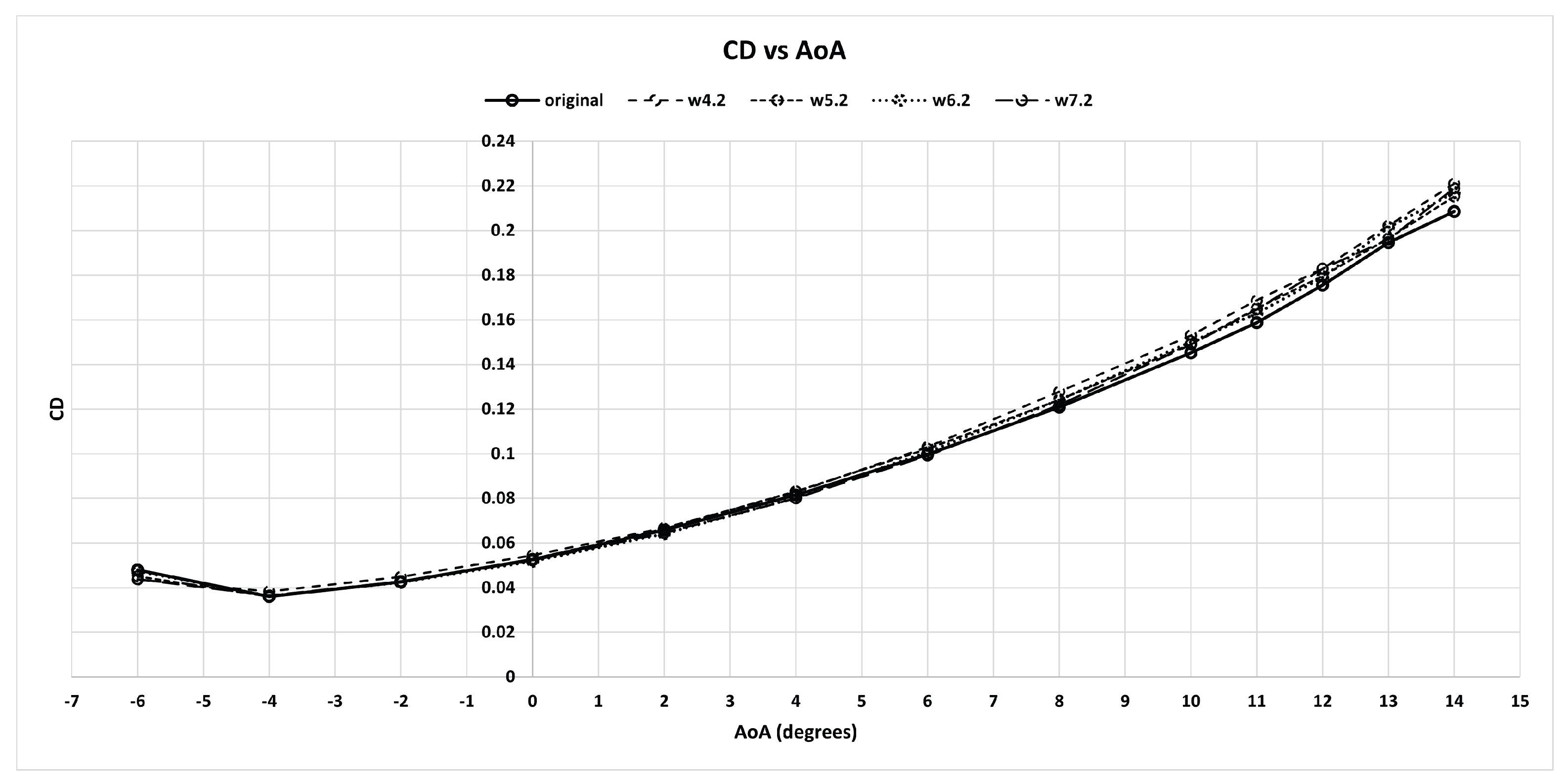
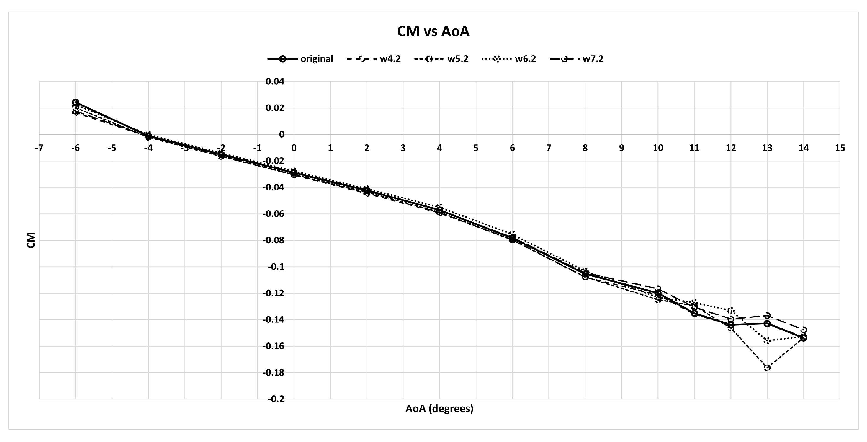
3.1. Aerodynamic Results and Comparison

The first step involves extracting key aerodynamic characteristics from high-fidelity CFD simulations. Figure 3, Figure 4, Figure 5 and Figure 6 illustrate the primary aerodynamic coefficients— C L , C D , C M , and C L / C D —for each model across various angles of attack (AoA). Table 2 presents the maximum lift coefficient, minimum drag coefficient, and maximum lift-to-drag ratio, along with their differences compared to the original configuration. The W 7.2 configuration achieved the highest increase in C L m a x (+4.48%) with a 1.29% rise in C D m i n . The maximum lift-to-drag ratio for all configurations, including the original design, occurs at zero degrees angle of attack ( 0 AoA), with the W 7.2 configuration again showing the largest positive difference.

3.2. Performance Evaluation

To evaluate the performance of each configuration, in terms of range and endurance in the cruise phase Equations (1) and (2) were used, as presented in [2]. These equations describe the range and endurance of a propeller-driven electric aircraft. In Equation (1), L/D is the Lift-to-Drag ratio, E s b is the battery-specific energy, η b 2 s the total system efficiency from the battery to the motor output shaft, η p the propeller efficiency, m b is the battery mass, and m the aircraft mass. Equation (2) has the same terms as Equation (1) including the term V, which is the aircraft velocity. The range (R) is maximized by flying at the speed with the best L / D . The best L / D is given at zero degrees AoA in each configuration. Thus, we assume that the aircraft flies at 0 o A o A and the velocity of the aircraft changes in each configuration to achieve the required lift force levels to achieve level flight. Therefore, based on these observations, the results for range (R) and endurance (E) are listed in Table 3.
R = 3.6 L D E s b η b 2 s η p g m b m ,
E = 3.6 L D E s b η b 2 s η p g V m b m ,

3.3. Optimal Configuration

In this subsection, the optimal winglet configuration will be selected, and results from high-fidelity simulations will be presented to compare it with the original UAV configuration. Based on Section 3.1 and Section 3.2, the optimal winglet configuration is identified as W 7.2 . Figure 7 and Figure 8 display the pressure coefficient contours on the wing surface. In the original configuration (Figure 7), airflow detachment occurs at the trailing edge of the wingtip due to vortex formation. With the addition of the winglet, this detachment is minimized, and the vortex is shifted to the winglet tip, where it appears significantly smaller, as shown in Figure 9 and Figure 10, which illustrates the Effective Prandtl Number in the area behind the wing. The turbulent flow caused by the wake of the wing is depicted by the red region; for the optimal configuration, the turbulent flow seems to be substantially smaller. Consequently, the lift coefficient increases while the drag coefficient decreases (see Table 4). The optimal configuration was further assessed for stability and control, with results compared to the Original configuration, as detailed in the following section.

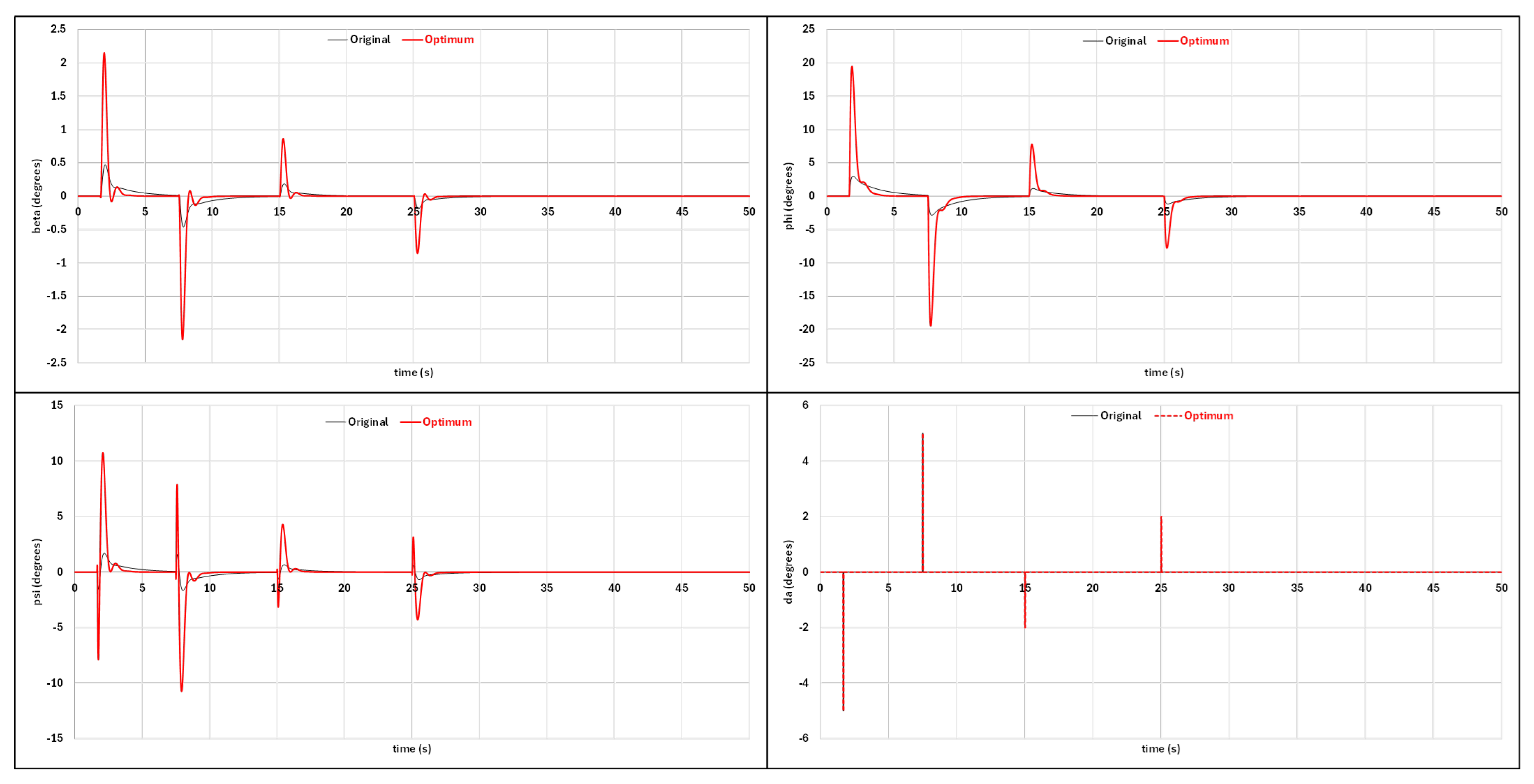
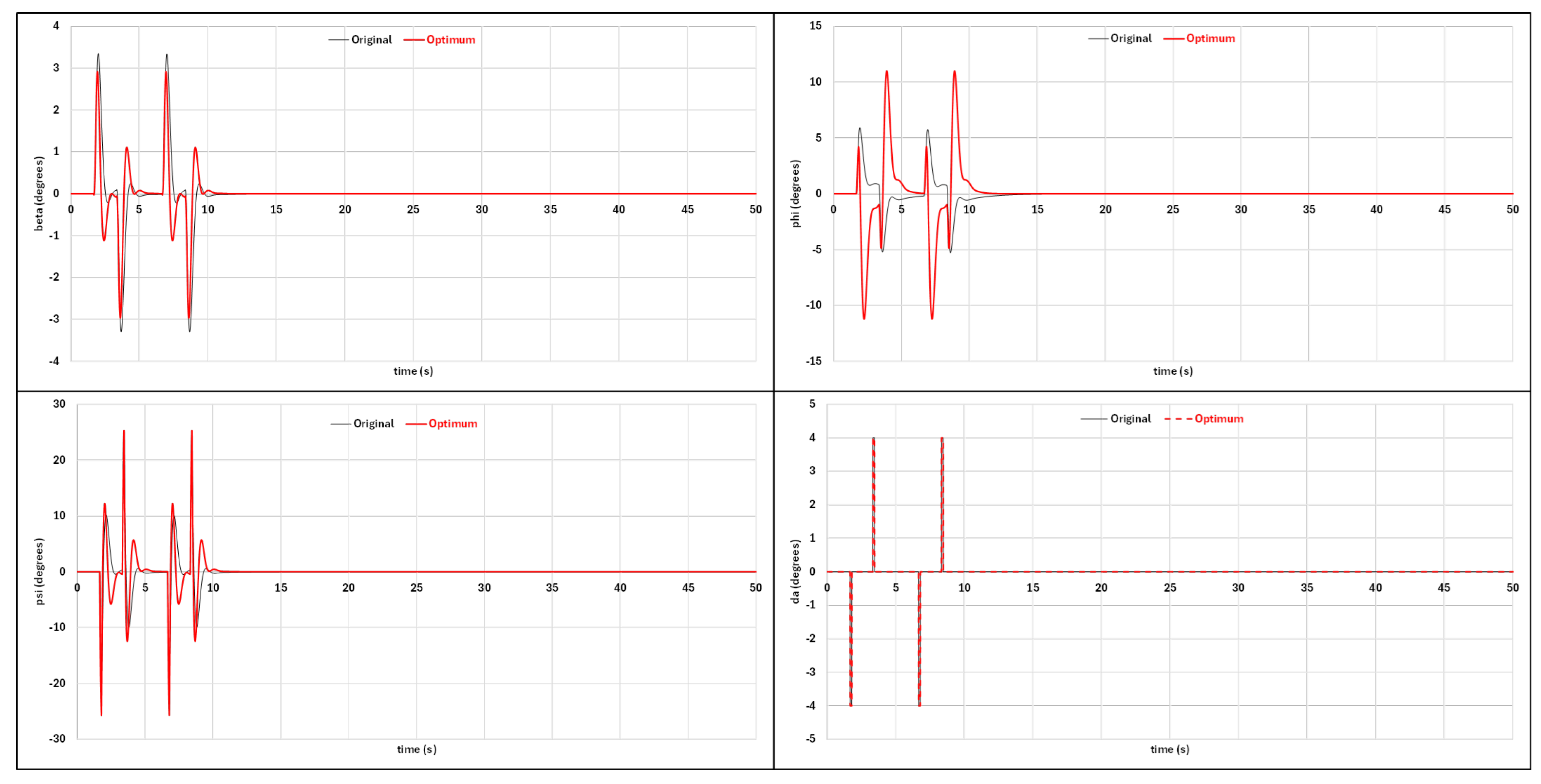
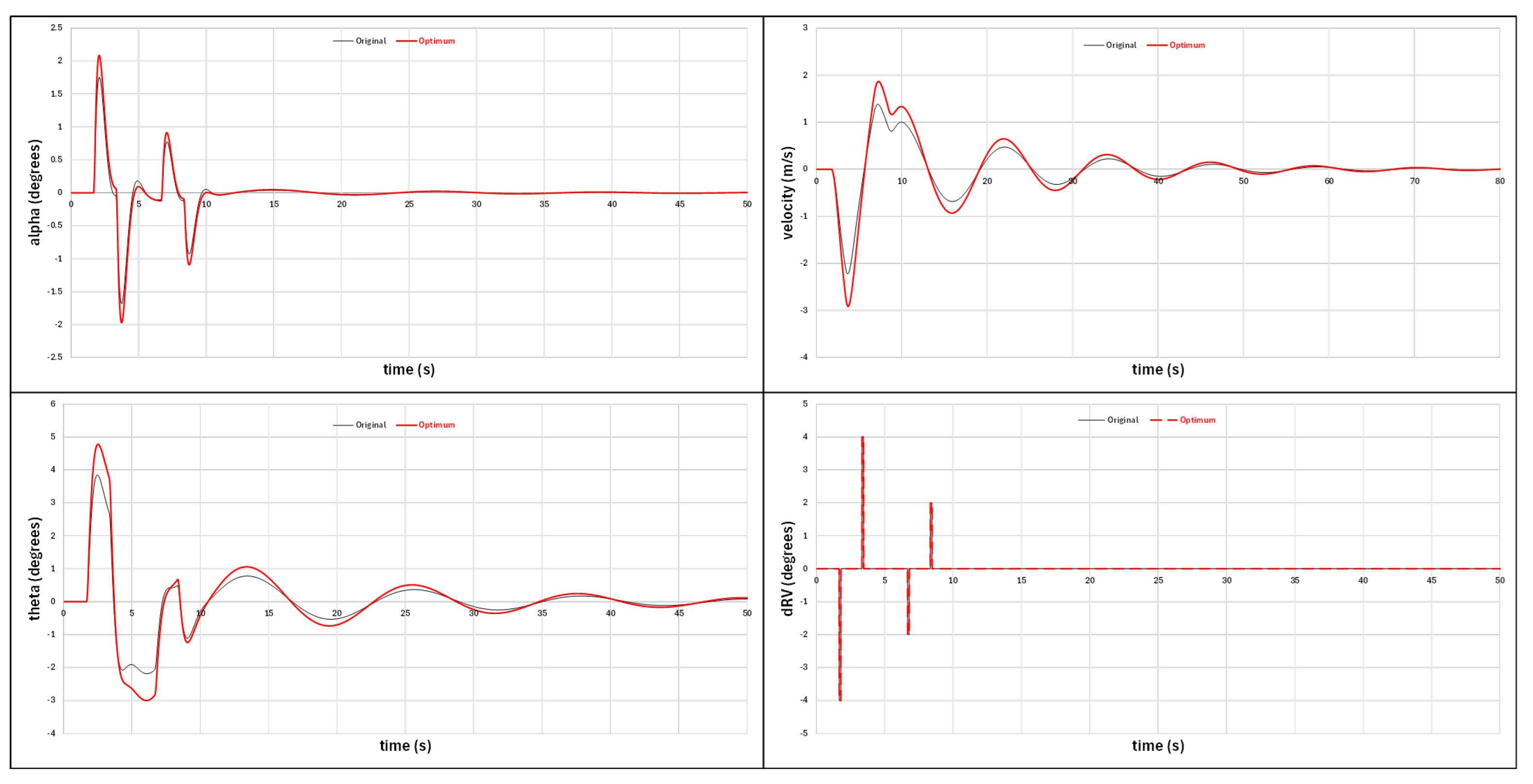
3.4. Stability and Control Evaluation

Following the performance evaluation, where the optimal winglet configuration for the UAV was selected, a stability and control assessment was conducted, comparing the optimized configuration with the original configuration. CFD analyses were performed to obtain stability and control derivatives for both configurations. Subsequently, a MATLAB (R2024b) simulation provided insights into the stability and control characteristics of each configuration. Figure 11 and Figure 12 illustrate the oscillations of sideslip angle ( β ), roll angle ( ϕ ), and yaw angle ( ψ ) along with the required aileron and ruddervator deflections for lateral stability during level flight (cruise phase). Figure 13 presents the poles for Spiral, Roll subsidence, and Dutch roll modes for both models. An increase in Spiral and Roll subsidence poles was observed, attributed to a rise in the C l β derivative caused by the added side area of the winglet, resulting in enhanced lateral stability.
Figure 14 and Figure 15 represent the longitudinal stability response of the UAV. Figure 14 shows the oscillations of alpha( α ), theta( θ ), and velocity(V) with the required ruddervator deflection. Phugoid and Short-period modes poles are presented in Figure 15. The differences observed here are mainly in the Phugoid mode pole, caused by the increase in C L a derivative.

4. Conclusions

In this study, various winglet designs were analyzed to determine their impact on the aerodynamic performance, stability, and control of a UAV, with the goal of identifying an optimal configuration. For all winglet configurations, the lift coefficient increases, while the drag coefficient remains nearly constant as in the original baseline configuration or decreases. This improvement is attributed to the additional surface provided by the winglet (particularly for blended winglets), resulting in a superior lift-to-drag ratio compared to the original configuration. The differences observed among the winglet designs are due to variations in their geometric characteristics and airfoil profiles. Designs with a symmetrical airfoil at the winglet tip produce smaller vortices, resulting in reduced drag. Based on the results in Table 3 and Table 4, the optimal winglet configuration is Winglet 7.2 (denoted as W7.2). CFD simulations indicate that this design generates smaller vortices at the winglet tip compared to the original design and eliminates flow separation at the wingtip. Additionally, vortex dissipation occurs sooner in the Optimal design. In terms of lateral stability, the Spiral and Roll Subsidence mode poles show a significant improvement in stability with the winglet, while the Dutch roll mode poles remain similar to those of the Original design. The oscillations in sideslip ( β ), roll ( ϕ ), and yaw ( ψ ) angles are comparable between designs, with a slight increase in oscillation amplitude but similar damping times. For longitudinal stability, the Phugoid mode poles are nearly identical for both the Original and Optimal designs. However, the Short Period mode poles indicate a slight improvement in longitudinal stability with the Optimal winglet. Oscillations in the angle of attack ( α ), pitch angle ( θ ), and velocity show a minor increase in amplitude, with damping occurring at nearly the same rate. In summary, the implementation of winglets on the UAV’s wing significantly enhances aerodynamic performance and provides a modest improvement in stability and control.

Author Contributions

Conceptualization, E.N. and E.K.; methodology, E.N.; software, E.N.; validation, E.N.; formal analysis, E.N.; investigation, E.N.; resources, E.N.; data curation, E.N.; writing—original draft preparation, E.N and S.K.; writing—review and editing, E.N. and S.K.; visualization, E.N.; supervision, S.K. and V.K.; project administration, E.N., E.K., S.K. and V.K.; All authors have read and agreed to the published version of the manuscript.

Funding

This research received no external funding.

Institutional Review Board Statement

Not applicable.

Informed Consent Statement

Not applicable.

Data Availability Statement

Data are available on request.

Conflicts of Interest

The authors declare no conflict of interest.

References

  1. Gudmundsson, S. General Aviation Aircraft Design: Applied Methods and Procedures; Butterworth-Heinemann: Oxford, UK, 2021. [Google Scholar]
  2. Raymer, D.P. Aircraft Design: A Conceptual Approach, 6th ed.; AIAA Education Series; American Institute of Aeronautics & Astronautics: Reston, VA, USA, 2018. [Google Scholar]
  3. Whitcomb, R.T. A Design Approach and Selected Wind-Tunnel Results at High Subsonic Speeds for Wing-Tip Mounted Winglets. Technical Report, National Aeronautics and Space Administration. 1976. Available online: https://ntrs.nasa.gov/citations/19760019075 (accessed on 1 March 2025).
  4. Gratzer, L.B. Blended Winglet. United States Patent No. 5348253, 20 September 1994. [Google Scholar]
  5. Panagiotou, P.; Kaparos, P.; Yakinthos, K. Winglet design and optimization for a MALE UAV using CFD. Aerosp. Sci. Technol. 2014, 39, 190–205. [Google Scholar] [CrossRef]
  6. Zhang, L.; Ma, D.; Yang, M.; Wang, S. Optimization and analysis of winglet configuration for solar aircraft. Chin. J. Aeronaut. 2020, 33, 3238–3252. [Google Scholar] [CrossRef]
  7. Eguea, J.P.; Bravo-Mosquera, P.D.; Catalano, F.M. Camber morphing winglet influence on aircraft drag breakdown and tip vortex structure. Aerosp. Sci. Technol. 2021, 119, 107148. [Google Scholar] [CrossRef]
  8. Utomo, M.T.S.; Yohana, E.; Mahendra, C.; Utama, I.Y. Analysis of blended winglet parameters on the aerodynamic characteristics of NXXX aircraft using Computational Fluid Dynamics (CFD). Results Eng. 2024, 24, 102901. [Google Scholar] [CrossRef]
  9. Roskam, J.; Lan, C. Airplane Aerodynamics and Performance; Airplane design and analysis, Roskam Aviation and Engineering; Darcorporation: Lawrence, KS, USA, 1997. [Google Scholar]
Figure 1. Winglet design methodology flowchart.
Engproc 90 00111 g001
Figure 2. Winglet configurations.
Engproc 90 00111 g002
Figure 3. C L v s A o A for Original, W4.2, W5.2, W6.2, and W7.2 configurations.
Engproc 90 00111 g003
Figure 4. C D v s A o A for Original, W4.2, W5.2, W6.2, and W7.2 configuration.
Engproc 90 00111 g004
Figure 5. C L / C D v s A o A for Original, W4.2, W5.2, W6.2, and W7.2 configuration.
Engproc 90 00111 g005
Figure 6. C M v s A o A for Original, W4.2, W5.2, W6.2, and W7.2 configuration.
Engproc 90 00111 g006
Figure 7. Pressure coeff. contours–Original conf.
Engproc 90 00111 g007
Figure 8. Pressure coeff. contours—Optimal conf.
Engproc 90 00111 g008
Figure 9. Eff. Prandtl number contours—Original conf.
Engproc 90 00111 g009
Figure 10. Eff. Prandtl number contours—Optimal conf.
Engproc 90 00111 g010
Figure 11. beta( β ), psi( ψ ) and phi( ϕ ) oscillations with aileron deflection.
Engproc 90 00111 g011
Figure 12. beta( β ), psi( ψ ) and phi( ϕ ) oscillations with ruddervator deflection.
Engproc 90 00111 g012
Figure 13. Lateral Stability poles—Spiral, Roll subsidence and Dutch roll modes.
Engproc 90 00111 g013
Figure 14. alpha( α ), velocity(V) and psi( ψ ) oscillations with ruddervator deflection.
Engproc 90 00111 g014
Figure 15. Longitudinal Stability poles—Phugoid and Short period modes.
Engproc 90 00111 g015
Table 1. Characteristics of UAV.
CharacteristicSymbolValue
Take-off weight (kg) W T O 14.3
Wing Area (m2) S r e f 0.6
Wingspan (m) b w 2.3
UAV length (m)l1.6
Wing Aspect RatioAR8.8
Wing Taper Ratio λ 0.5
Wing root chord (m) C r 0.375
Battery mass (kg) m b 2.6
Battery Spec. Energy (kW/kg) E s b 145
Total system efficiency (battery to motor output shaft) η b 2 s 0.9114
Propeller efficiency η p 0.785
Table 2. Aerodynamic coefficients results.
A/AConfig. C Lmax C Dmin C L / C D max C Lmax Div . C Dmin Div . C L / C D max Div .
1Original1.61330.036015.9440---
2W11.61900.036916.15210.35%2.46%1.29%
3W1.11.61980.036916.25600.40%2.54%1.92%
4W21.61220.036616.1189-0.07%1.68%1.09%
5W2.11.62120.036616.22720.49%1.70%1.75%
6W31.62500.036316.19500.72%0.80%1.55%
7W3.11.62680.036416.22940.83%0.99%1.76%
8W41.66080.038416.77892.86%6.37%4.98%
9W4.11.65670.038417.21582.62%6.21%7.39%
10W4.21.65750.037517.71372.67%4.14%9.99%
11W51.64570.037616.16371.97%4.34%1.36%
12W5.11.64820.036816.61842.12%2.07%4.06%
13W5.21.61750.036016.81570.26%0.14%5.18%
14W61.63850.036317.18931.54%0.82%7.24%
15W6.11.66640.036317.44193.19%0.89%8.59%
16w6.21.67530.036317.67823.70%0.83%9.81%
17W71.65620.037217.03142.59%3.22%6.38%
18W7.11.65530.036817.48242.54%2.23%8.80%
19W7.21.68890.036517.81794.48%1.29%10.52%
20W7.31.64870.036817.71842.15%2.26%10.01%
Table 3. Range and Endurance results.
A/AConfig.Range (km)Endurance (hr)Range Div.Endurance Div.
1Original110.371.34--
2W1111.811.381.29%3.06%
3W1.1112.531.391.92%3.80%
4W2111.581.371.09%2.52%
5W2.1112.331.381.75%3.30%
6W3112.111.371.55%2.64%
7W3.1112.351.381.76%2.9%
8W4116.151.464.98%8.64%
9W4.1119.181.527.39%12.24%
10W4.2122.621.589.99%15.33%
11W5111.891.391.36%3.79%
12W5.1115.041.434.06%6.50%
13W5.2116.411.455.18%7.79%
14W6118.991.497.24%10.02%
15W6.1120.741.528.59%11.97%
16W6.2122.381.559.81%13.63%
17W7117.901.486.38%9.60%
18W7.1121.021.538.80%12.78%
19W7.2123.341.5710.52%14.94%
20W7.3122.651.5810.01%15.20%
Table 4. Aerodynamic coefficients at zero angle of attack.
A/AConfig. C L 0 C D C L 0 V cruise C L 0 Div . C D C L 0 Div .
1Original0.8410.052722.93--
2W10.8720.054022.513.56%2.30%
3W1.10.8740.053822.493.79%1.91%
4W20.8660.053722.592.87%1.81%
5W2.10.8680.053522.563.14%1.42%
6W30.8600.053122.672.21%0.67%
7W3.10.8610.053122.662.35%0.60%
8W40.9100.054222.047.57%2.73%
9W4.10.9360.054421.7210.21%3.05%
10W4.20.9500.053621.5711.51%1.69%
11W50.8840.054722.364.86%3.55%
12W5.10.8850.053322.345.03%1.02%
13W5.20.8890.052922.305.42%0.25%
14W60.8930.052022.245.89%−1.46%
15W6.10.9070.052022.087.27%−1.44%
16W6.20.9170.051921.968.28%−1.69%
17W70.9020.052922.146.76%0.40%
18W7.10.9190.052621.928.55%−0.28%
19W7.20.9300.052221.799.63%−0.99%
20W7.30.9470.053421.6111.19%1.31%
Disclaimer/Publisher’s Note: The statements, opinions and data contained in all publications are solely those of the individual author(s) and contributor(s) and not of MDPI and/or the editor(s). MDPI and/or the editor(s) disclaim responsibility for any injury to people or property resulting from any ideas, methods, instructions or products referred to in the content.

