1. Introduction
In the global economy, Low Earth Orbit (LEO) satellites are of increasing importance in asset tracking, vehicular navigation and emergency communication, among others. The main enabler for this is the decline in the cost of launching satellites into LEO, which plays a vital role in opening up this ‘New Space’ economy [
1]. These launch costs have been steadily declining over the past decade, thus opening up new opportunities for companies to design, develop, and launch constellations.
Indoor signal coverage has always been challenging for higher-orbiting satellite constellations such as the Global Positioning System (GPS) [
2]. This is due to the limited Power on Ground (PoG) provided by these satellites, which could lead to unreliable services and bad connectivity in indoor environments. LEO satellites could provide a solution to this problem, due to the shorter path the signal must travel to reach the User Equipment (UE) [
3]. This indoor connectivity unmistakably could be used by a wide variety of applications such as asset tracking, vehicular navigation, and emergency communication [
2]. Multiple LEO constellations are currently operational, which facilitates the possibility of conducting real-world experiments of the indoor signal strength [
4]. Furthermore, calculating wall material losses quickly becomes very difficult due to a large number of variables to take into account [
2,
5]. Therefore, in-situ measurements are the preferred method [
2].
In this work, we provide a coverage analysis of different indoor environments for the Orbcomm satellite constellation. This constellation provides a downlink in the Very High Frequency (VHF) band, which could result in better indoor coverage. More specifically, the constellation utilizes a downlink frequency range of 137 MHz up to 138 MHz. Our contribution is (1) an assessment of the limits and possibilities of indoor coverage of Orbcomm LEO satellites, and (2) a quantification of how strong these Orbcomm satellite signals propagate into different indoor environments.
This paper is outlined as follows.
Section 2 analyses similar, previously conducted studies on this topic.
Section 3 provides an outline of the research methodology.
Section 4 supplies the results in terms of coverage and
Section 5 discusses these results. Finally,
Section 6 draws the conclusion of the research.
2. Related Work
A limited amount of studies have been conducted on the topic of the indoor signal strength of LEO satellites. A few experiments have already been conducted using the Iridium constellation, which utilizes the L-band frequency (1610 MHz up to
MHz) to transmit downlink packets [
6,
7]. However, higher frequencies experience significantly more wall attenuation than lower frequencies [
5].
A first study simulated the differences in the Carrier-to-Noise Density Ratio (
) between LEO constellations and Medium Earth Orbit (MEO) constellations in an indoor environment. Ferre et al. have shown that in simulation, the indoor
of LEO satellites is similar to the outdoor
of Medium Earth Orbit satellites [
8]. More specifically Starlink, OneWeb, and Kuiper, which are all situated in LEO, showed a similar indoor
to the outdoor
of the Galileo constellation which is situated in MEO. In the simulation the outdoor
of Galileo is
dB-Hz, similar results were observed for Starlink, OneWeb and Kuiper in an indoor setting. More specifically, the Starlink constellation had an indoor
of
dB-Hz, the OneWeb Constellation had a
of
dB-Hz and Kuiper had a
of
dB-Hz. To conduct this simulation, the QUAsi Deterministic RadIo channel GenerAtor (QuaDRiGa) framework was used in addition to MATLAB [
9]. Furthermore, the frequencies used in the simulation matched with the real constellation frequencies as well as the antenna parameters [
8]. The values put forward in this paper do deviate from what is commonly found in other papers. Specifically, the outdoor
of GPS typically ranges between 30 dB-Hz and 50 dB-Hz which was not the case in this paper [
7,
10].
Second, a study by Reid et al. conducted real-life measurements of the
of LEO satellites [
6]. These experiments were performed in a 13-story office building. The experiment consisted of measuring the
of Iridium Satellite Time and Location (STL) signals. Additionally, a GPS receiver was used to evaluate if the Ground Receiving Station (GRS) could use this MEO constellation to locate itself. The results of this study showed that even on the 13th floor the GPS signals could not penetrate inside well enough to determine the location. A minimum of four satellite signals are necessary to determine the location of the receiver and in this study, only one to two satellite signals arrived strong enough to decode. In contrast to the Iridium STL signals, which were received with high
on the 13th floor. Moreover, the Iridium STL signals even arrived with high
inside on the second floor. More specifically, these signals arrived with a
between 45– 55 dB-Hz [
6].
A third and last study, similar to that of Reid et al., was conducted by Enge et al. They measured
inside a metal container [
7]. These measurements showed that the
of the Iridium STL signals inside of the container were similar to that of GPS in an outdoor environment (± 45 dB-Hz).
The above studies have shown the potential of indoor satellite communication from LEO. However, a more complete picture in terms of environments is needed to judge the feasibility. Hence, this work aims to analyze the received signal strength in different indoor rooms and floor levels.
3. Material and Methodology
We will analyze the signal strength in various outdoor and indoor environments. To evaluate the link quality, two parameters are commonly utilized. The first parameter is the Carrier-to-Noise Ratio
. Which is the ratio of carrier power over noise power in the channel [
3]. This parameter is a good indicator of system performance and can be calculated as such [
11]:
with
in dB,
is the carrier power in dBW and
is the noise power in dBW [
3]. The second commonly used parameter is the
which is the ratio of carrier power to the noise power per unit bandwidth. To calculate the
the following formula can be used [
3]:
with
in dB-Hz,
in dB and
the bandwidth in dB-Hz.
3.1. Receiver Setup
To measure the signal power of Orbcomm satellites in different environments, we constructed a receiver, which consists of a Software Defined Radio (SDR) and an antenna connected via a one-meter coaxial cable. In what follows, we will further describe these components.
An SDR provides a flexible and versatile radio platform [
12]. Previously, these physical layers were implemented in hardware, but hardware redesign can be time-consuming and costly. The SDR, by contrast, has the possibility to adapt to different protocols, bandwidths, as well as frequencies [
13]. Furthermore, the data can easily be saved and post-processed. This makes it a great choice for this type of research. For this paper, the Ettus B210 was used which has the ability to receive signals between 70 MHz and 6 GHz and with a maximum bandwidth of up to 56 MHz. This SDR utilizes the AD9361 chip which is a high-performance transceiver [
14]. The two receivers onboard feature a 12-bit resolution and a configurable gain between 0 and
dB. When the center frequency is set to 800 MHz, the Noise Figure (NF) is equal to 2 dB and the accuracy is ±2 dB [
15]. The NF is not indicated for the frequency range that we utilize, therefore, this is the closest available value.
Two main factors should be taken into account when selecting a receiving antenna from the wide range of available options. First, the polarization of the transmitting antenna on the satellite should ideally match the polarization of the GRS antenna, otherwise, this will result in polarization losses. Second, the gain of the antenna should be taken into account. A high-gain antenna results in a stronger received signal but requires tracking the satellites, whereas an omnidirectional antenna does not require tracking [
3,
16].
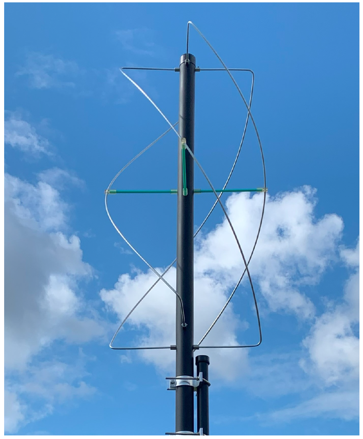
For our setup, we selected an antenna which was optimal for receiving the Orbcomm constellation. This constellation utilizes a Right Hand Circular Polarized (RHCP) signal with downlink frequencies between 137 MHz and 138 MHz. Therefore, we selected the Diamond DPKE137 antenna, as shown in
Figure 1. This antenna is a RHCP quadrifilar helix antenna designed to receive this frequency band [
17]. The quadrifilar helix antenna is an improved version of the regular helical antenna. Adding extra windings tightens the radiation pattern and minimizes sidelobes. Moreover, the quadrifilar helix antenna is more omnidirectional than the helical antenna [
18].
3.2. The Orbcomm Constellation
Since 1995, the Orbcomm satellite constellation has provided users with the ability to transmit and receive information in remote areas. Multiple sectors leverage this constellation, such as the maritime sector which uses the Orbcomm satellite constellation to transmit and receive Automatic Identification System (AIS) data. Furthermore, in the transport sector, the constellation is used to track and get status updates from vehicles [
19].
The Orbcomm system consists of UE, a space segment, and Earth stations. The space segment consists of two generations of satellites, namely, Orbcomm Generation 1 (OG1) and Orbcomm Generation 2 (OG2). The characteristics of the constellation as they were designed can be found in
Table 1.
The Orbcomm space segment functions as a link between the user and a gateway station on Earth. The satellites transmit a constant downlink signal that user devices can tune into. On this downlink channel, user devices can find the active uplink channels of that satellite. The user device can use these channels to transmit data to the satellite, which in turn relays it to the Earth gateway station. The downlink frequencies are positioned between 137 MHz and 138 MHz and the antenna subsystem of these Orbcomm satellites consists of a RHCP quadrifilar helix antenna which transmits with an Effective Isotropic Radiated Power (EIRP) of 12 dBW [
20].
The 137– 138 MHz band is not exclusively used by Orbcomm for downlink communication. Multiple meteorological satellites use this frequency range to communicate, for instance, the National Oceanic and Atmospheric Administration (NOAA) satellites have multiple downlink channels in this band [
20]. The band is also used by the recently launched SpaceBEE constellation [
4]. Despite the shared use of this frequency band, there is no overlap between these systems. They each use their own well-defined frequency ranges within this band [
20].
Currently, the Orbcomm constellation does not exactly meet the specifications of
Table 1. At the time of writing, the actual OG1 constellation consist of 22 functional satellites and one semi-operational satellite. Most of the OG1 satellites are currently also in a lower orbit which is between 750 km and 790 km [
21]. The OG2 constellation consists of 12 functional satellites [
21]. Some confusion surrounds this subject since at the moment, even the official Orbcomm website does not correctly display which satellites are operational [
19]. However, ‘operational’ does not necessarily mean that the satellite is actively transmitting. During the measurement campaign, very few signals from OG1 satellites were received. This is in contrast with the operational OG2 satellites, which are all actively transmitting.
3.3. Data Processing
In this paper, multiple satellite passes were recorded. These recordings were scheduled in SDR Console, a software program used to record the incoming IQ data. The recording starts once a satellite reaches an elevation angle of 5° and continues as long as the satellite remains at an elevation angle above 5°. This window of recording was calculated with the help of Two Line Element (TLE) files. These publicly available files precisely define the current orbit of satellites and can be used to predict the future trajectory [
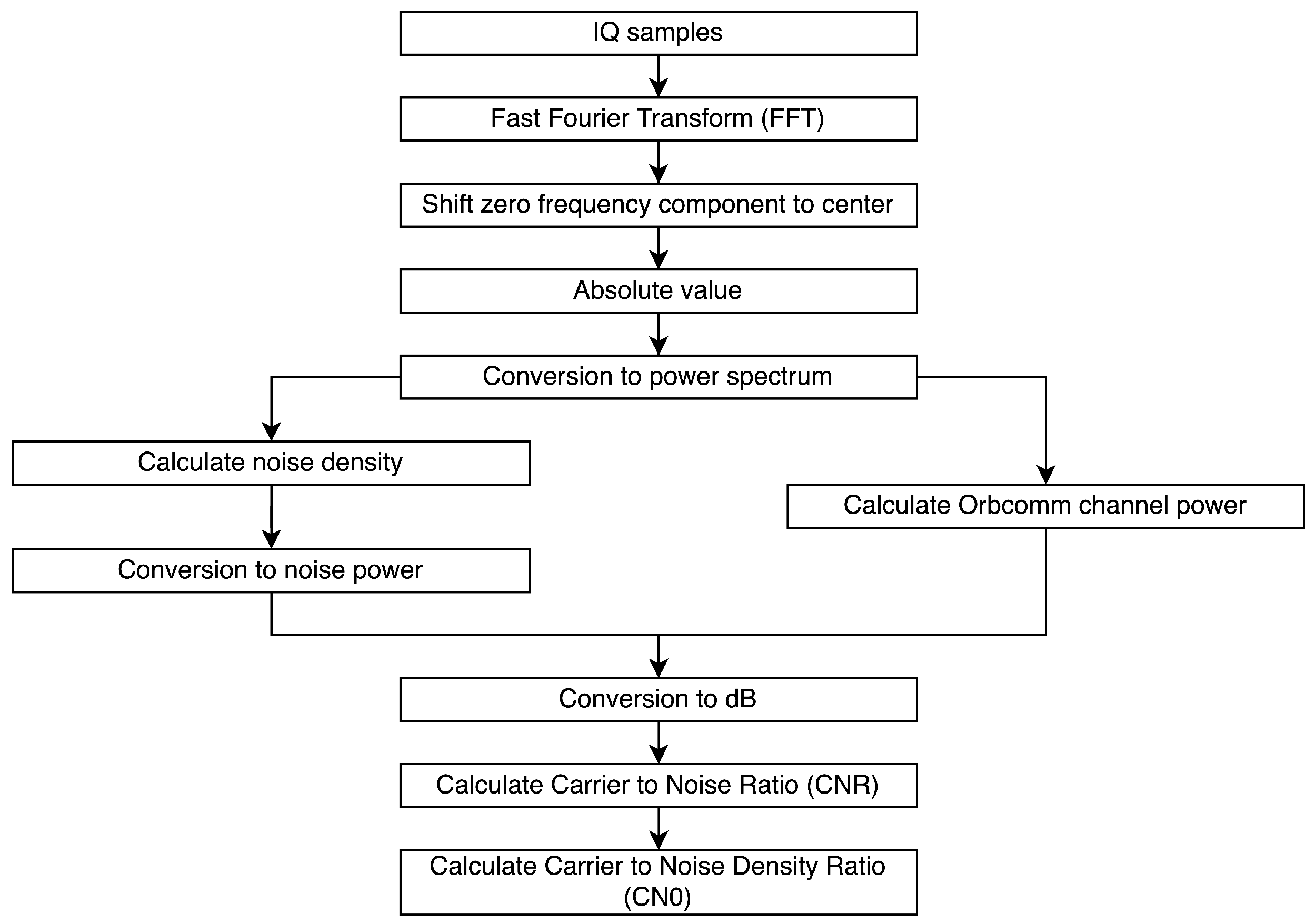
21]. In practice, this resulted in recording fragments of about 12–15 min. The sample rate of the SDR was set to 1 MHz and captured the full Orbcomm downlink spectrum from 137 MHz to 138 MHz. After recording the satellite passes, the data is processed offline. The processing flow is illustrated in
Figure 2. Firstly, the recording gets split into 1 s fragments and fed into the processing algorithm where it is windowed to prevent spectral leakage [
22]. After this, the conversion to the frequency domain is made by applying a Fast Fourier Transform (FFT). The zero frequency component is shifted to the center and the absolute value is calculated. Then, we make the conversion to the power spectrum [
22]. To calculate
, first, the average noise power per bin is calculated. This is done by sorting the bins and discarding the highest bins that match the active Orbcomm channels and DC bin. Subsequently, the noise density is calculated. To get an estimate of the noise power in the Orbcomm channel, the noise density is multiplied by the bandwidth. Following this, the conversion to dBW is made. To calculate
, the peak bin within an Orbcomm channel is identified and the surrounding bins are summed. Afterwards, the conversion to dBW is made. Finally, to calculate the
and
the formulas of
Section 3 are employed.
3.4. Environmental Influences on Measurements
Due to external influences, measurements at different points in time or at different locations will never be exactly the same. One of the most significant influences is interference. In an indoor environment, many electrical devices are present and most of them emit some sort of Radio Frequency Interference (RFI). Additionally, the ionospheric Total Electron Content (TEC) changes over time and this results in different scintillation effects. Ionospheric scintillation results in rapid fluctuations of the amplitude and phase which is caused by electron density irregularities and has been observed the most on VHF frequencies [
3].
5. Discussion
In this study, we found that the Orbcomm satellite signals propagated into all rooms of a suburban home. We compared and quantified signal strength in various environments, the results of which are summarized in
Figure 4, illustrating the differences between the environments.
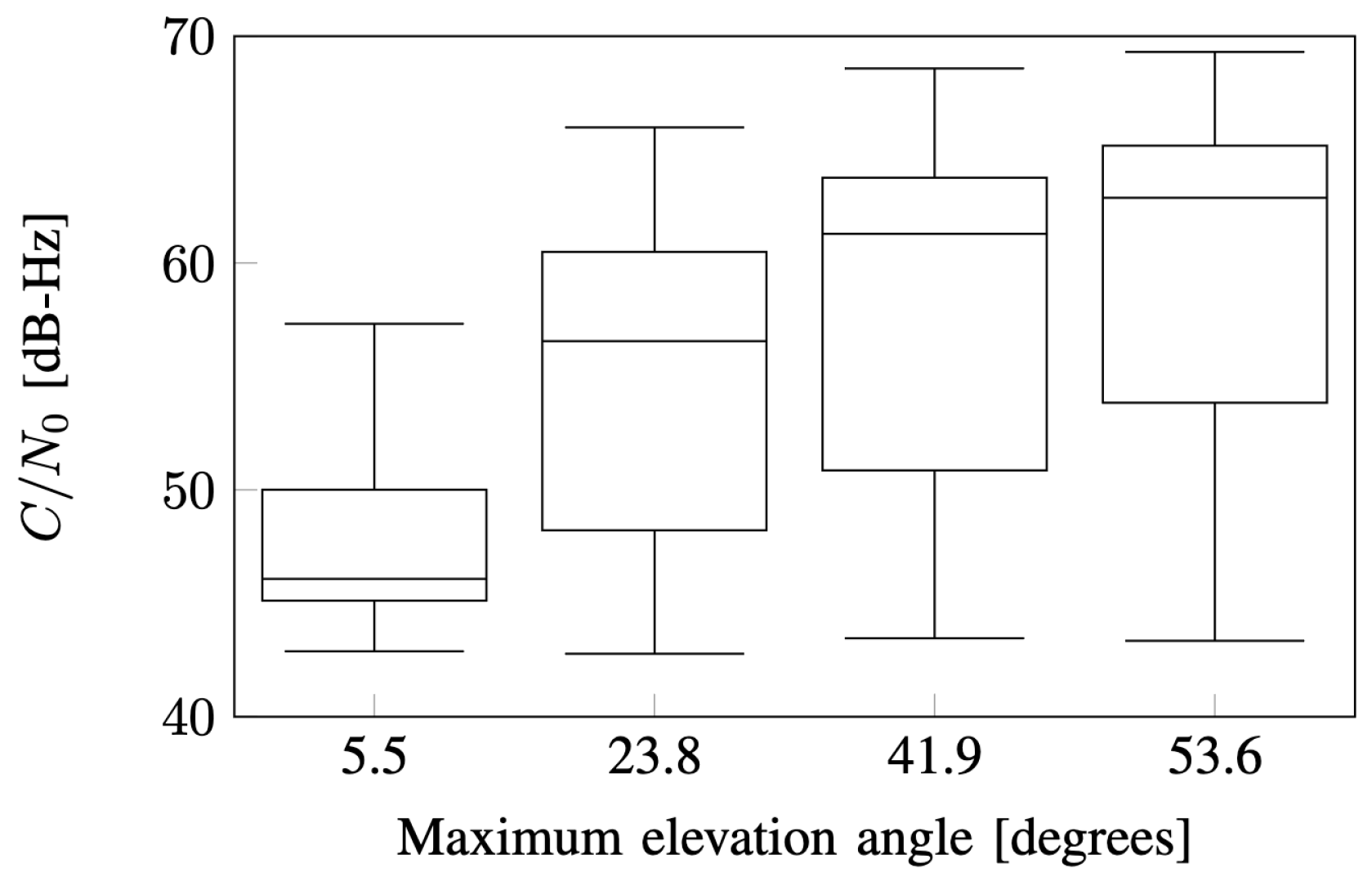
When examining the results from the outdoor measurements, a clear correlation between elevation angle and signal strength is present, which is to be expected. This can be observed in
Figure 3. Despite the less-than-ideal conditions in the suburban environment, the signal was still received remarkably strong. The indoor signal strength is notably weaker. In the attic, the strongest signals were received out of all indoor environments. When comparing the 40° maximum elevation angle range of the attic to the outdoor measurements, the peak adjacent values are 13 dB-Hz lower. Similarly, the median is
dB-Hz lower. When analyzing the median of the other rooms, it can be observed that the first floor is
dB-Hz below the outdoor median and the ground floor
dB-Hz below the outdoor median. Finally, the median
of the basement is
dB-Hz below the outdoor median. Remarkable is that the median
of the ground floor at low elevation angles is higher than the one of the first floor, which might be due to the large windows. Another aspect to consider in indoor environments is that a higher elevation angle does not necessarily imply a higher signal strength, as is illustrated in
Figure 4. In an indoor environment, material attenuation also plays a significant role in link performance. The attenuation is influenced by the elevation angle but also the azimuth angle of the satellite.
When comparing our work to the one conducted by Reid et al., some similarities and differences can be identified. Reid et al. also conducted real-life measurements of the
. However, these measurements were of Iridium satellites inside an office building. The
results varied between 45 and 60 dB-Hz on the higher floor levels and between 45 and 55 dB-Hz on the lower floor levels [
6]. It is important to note a significant distinction between the study by Reid et al. and the present study. Specifically, this work utilizes the Orbcomm satellite constellation, which operates in the VHF frequency range and has an EIRP of 12 dBW [
20]. This differs from the Iridium constellation used by Reid et al., which utilizes a bursty L-Band downlink with an EIRP between
dBW and
dBW [
4]. Therefore, some differences in results are to be expected. Nonetheless, this study indicates that the Orbcomm constellation results in similar
values in the attic and on the ground floor as the Iridium constellation on the lower floors of an office building.
Furthermore, when comparing our
results to those of GNSS, a distinctly higher
can be observed from the Orbcomm constellation. The
of GPS in an outdoor environment is approximately 45 dB-Hz [
7], whereas the Orbcomm satellites reach a peak
of approximately 70 dB-Hz in an outdoor environment. Furthermore, the Orbcomm LEO satellite signals exhibit high
indoors even in comparison to outdoor GPS signals, reaching higher values as GPS in every location. However, it should be noted that in this study, we were unable to detect signals with a CNR below 0 dB. Thus, the lowest value we were able to detect was
dB-Hz.
6. Conclusions
The aim of this research was to evaluate the indoor coverage of Orbcomm satellites within a suburban setting. These satellites operate in LEO and transmit on the VHF band. By conducting multiple outdoor and indoor measurements, we examined the variations in signal strength across different environments. More specifically, the attic, the first floor, the ground floor, the basement and the garden were evaluated. Undoubtedly, the outdoor satellite signals were most strongly received. Furthermore, a clear correlation between a higher elevation angle and a higher signal strength was present. In an indoor setting, the satellite signals were received most strongly in the attic. However, a substantial difference in signal strength between outdoor and indoor was noted. Furthermore, similar signal strengths were observed on the above-ground floors. Notably, the Orbcomm satellite signals were received in the basement, which is constructed out of thick concrete walls and slabs, albeit with low power and only for a short duration of time.
Overall, this study proves that the Orbcomm satellite signals penetrate deeply indoors. The signals even arrived with high carrier-to-noise density ratio in multiple environments. The high Power on Ground highlights the feasibility of indoor satellite communication, which is simply not possible with the current implementation of Global Navigation Satellite Systems (GNSS) in MEO. Therefore, along with the declining costs associated with launching them, LEO satellites offer an interesting opportunity for future indoor satellite communication and navigation applications.


