Abstract
In this work, a novel analytical equation is developed to accurately predict the mechanical behavior of thin-walled beams. The FEM was used for building the model and obtaining the results. The new equation developed is useful for the calculation of the displacement of a beam simply supported at its ends subjected to torsion loads, applied in opposite side areas of the Finite Element Method (FEM) model. The software Eureqa 1.24.0 was used to find hidden analytical models that were validated thereafter. The aim is to provide a formula that makes possible the comparison of analytic calculations with numerical calculations on bending and torsion combined load. A FEM model of a hollow-box beam with rectangular cross-section loaded with torsion was built and analytical calculations were performed. The analytic calculations were compared with the numeric results in order to know if the results are approximated. The results show good agreement. In the future, other models, such as internally reinforced beams, could also be tested with this methodology. Also, different conditions could be applied to the model studied in this work in order to evaluate the limitations and validity of the developed analytical model.
1. Introduction
Engineers utilize thin-walled hollow-box beams a lot because they are strong for their weight and efficient in terms of structure. To accurately forecast how they will act when there are both torsion and bending loads, you need a torsional displacement equation that is both correct and works with bending behavior. But even after many studies, a generic, proven analytical model for this purpose is still hard to find. Vo and Lee [1] looked at how bending and torsion work together in composite closed-section box beams. Their work gave us useful information about how stiffness changes. Still, their conclusions cannot be directly applied to isotropic thin-walled rectangular beams because they only looked at composite materials. Lukić and Zrnić [2] also looked at the flexural–torsional vibration of beams that were loaded axially, focusing on coupled deformation modes. This study is useful for dynamic analysis, but it does not give us clear tools for predicting static deflection under torsion. Wan and Mahendran [3] looked into how bending stress changes the torsional rigidity of rectangular shapes. Even though their results show how important it is to think about how stiffness changes, they did not come up with a way to anticipate displacement using math. Xu et al. [4] came up with a higher-order beam theory for analyzing buckling under difficult loading and boundary conditions. Their study moves theoretical modeling forward, but it is mostly about buckling and takes a lot of computer power to run. Kim and Kim [5] looked into twisted box-section beams, focusing on how well they worked structurally. But their shapes are different from the straight beam shapes that are usually used in real life. Eisenberger [6] talked about torsional analysis in bars with varying cross-sections, but his model does not work for thin-walled rectangular beams with fixed geometry. Vinson [7] gave us a basic idea of how thin-walled structures behave when they are under different types of stress. This work is very thorough; however, it is more of a theoretical overview than a source of proven predictive models. Wan and Mahendran [8] looked at hollow flange channel sections to find out how strong they were when twisted. But their work is mostly about strength and failure, not how things bend. Seo et al. [9] came up with a way to use numbers to predict lateral distortional buckling in beams having web openings. Their method improves the accuracy of designs, but it is still numerical and does not produce an analytical displacement equation. Paczos [10] did experiments on non-standard flange C-beams, which gave useful information but does not apply to hollow-box rectangular profiles in general. Chen et al. [11] looked into how cold-formed steel beams behave when they are bent unevenly and how they interact with each other. Their paper is interesting from an experimental point of view, but it does not look at torsional loading. Finally, Banerjee and Biswas [12] looked into flexural–torsional buckling in composite materials. This helped us grasp how buckling works, but they did not give us any analytical solutions for torsional displacement in rectangular isotropic beams.
Together, these studies provide a strong foundation for developing a torsion displacement equation that ensures compatibility with bending in thin-walled hollow-box beams, addressing both theoretical and experimental aspects. While previous studies have explored the structural performance of thin-walled beams, there is a lack of simple, validated analytical equations that specifically predict torsional displacement in rectangular thin-walled hollow-box beams. The existing equations fail to predict the behavior for beam with low-to-moderate thickness. The study aims to develop an analytical equation that accurately predicts the deflection of thin-walled hollow-box beams under torsional loads.
2. Numerical Procedure
In this work, linear static analyses were done in the FEM software ANSYS Workbench 2025 R1. One of the numerical models, with a single concentrated load and degree of freedom constraints, is shown in Figure 1a,b, in different angles. Figure 1c shows the supports/fixture of the beam, which is in its entire lower face, as shown in blue color.
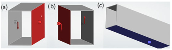
Figure 1.
FEM model showing applied loads (a,b) and supports/fixture (c).
The applied binary load has an intensity of 10,000 N and was applied on the side faces/areas, as shown in Figure 1a,b. Areas where the loads are applied are shown in red. The binary forces, generating a torque, are shown in red arrows, in the same figures. The models are constrained at the lower face/area. As the type of analysis performed is linear static, the strength limits of the material were not considered for yield. For this reason, ANSYS assumes that the results always vary linearly with the intensity of the applied loads. For FEM modeling purposes, the material properties are those of the structural steel: Young modulus E is 2 × 10¹¹ Pa, the Poisson coefficient ν is 0.3 [−] and the density ρ is 7850 kg/m3. The mesh applied to the FEM model is shown on Figure 2.
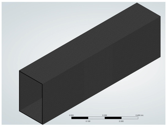
Figure 2.
Meshed model.
The element size of the mesh shown in Figure 2 is 3 mm. The mesh type is quadrilateral mapped. The element used was SOLID186. That element type was selected automatically by ANSYS Workbench. With the selected element size of 3 mm, the number of elements of the model is 218,770. The parameters of the samples studied are shown in Table 1. In Table 1, t is the thickness, b is the section width, h is the section height and L is the length.

Table 1.
Samples studied.
3. Results and Discussion
3.1. Mesh Convergence
A mesh sensitivity analysis was performed to select the element size that yields the most accurate results for the numerical model. Element sizes of 96, 48, 24, 12, 6 and 3 mm were studied. The y deflection results are shown in Figure 3.
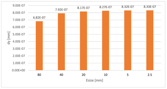
Figure 3.
Mesh convergence results—y deflection.
The results of Figure 3 were analyzed by means of Equation (1):
where δyx is the deflections by the model with the highest element size of the comparison and δyx−1 is the deflections by the model with the lowest element size of the comparison. Figure 4 shows results calculated with Equation (1), using the deflections shown in Figure 3.
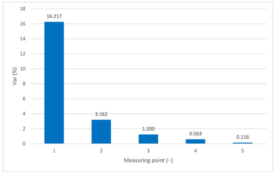
Figure 4.
Mesh convergence results—Error.
The element size of 3 mm was selected as it results from the lowest error of all element sizes.
Figure 3 and Figure 4 present the mesh convergence analysis, which is crucial for ensuring the reliability of the FEM results. In Figure 3, the y-direction deflection values for various mesh sizes (ranging from 96 mm to 3 mm) show increasing precision as the mesh is refined. Figure 4 quantifies the relative error between successive mesh sizes, showing a clear decrease in error with finer meshes. The smallest element size of 3 mm yielded the lowest error, indicating an optimal balance between accuracy and computational efficiency for the FEM model.
3.2. Validation of the Equation
In this section, the numerical results obtained in ANSYS are compared with the analytical ones, obtained by the new equation (Equation (2)). Equation (2) was obtained in the software Eureqa, from the company Nutonian [13,14], by using the dataset of Table 1 as input, as well as the numerical deflections shown in Figure 5. A similar study was performed for ribbed plates in [15].
where δyn is the deflections by the numerical method and δya is the deflections by the analytical method.
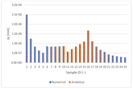
Figure 5.
Comparison between analytical results (by the new equation) and the numerical results (obtained in ANSYS Workbench 2025 R1): y deflection.
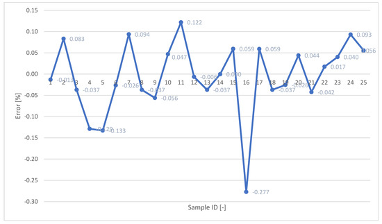
Figure 6.
Comparison between analytical results (by the new equation) and the numerical results (obtained in ANSYS Workbench 2025 R1: errors.
Figure 5 and Figure 6 compare the deflection results from the newly developed analytical equation with those obtained from the FEM simulations. Figure 5 shows a strong visual correlation between the analytical and numerical results across different beam configurations. Figure 6 provides a quantitative assessment of the accuracy, with the relative error (as defined in Equation (3)) remaining below 0.3% in all cases. The maximum observed error of 0.277% confirms that the analytical model performs with high precision and is closely aligned with the FEM data. Overall, the results demonstrate that the analytical equation reliably reproduces the FEM outcomes, validating its use for predicting torsional displacement in rectangular thin-walled hollow-box beams. The low error rates suggest that the model can serve as a practical alternative to time-consuming numerical simulations in many engineering applications.
This study developed and validated a new analytical equation for predicting linear torsional deflection in simply supported thin-walled hollow-box beams with rectangular cross-sections. The equation was derived using simulations in ANSYS Workbench 2025 R1 and symbolic regression with Eureqa software. Validation results showed excellent agreement, with a maximum error of only 0.277%, confirming the equation’s high accuracy within the tested geometrical and loading conditions. A key aspect of this work was the mesh convergence analysis, which ensured the reliability of the FEM results. As the mesh was refined from 96 mm down to 3 mm, deflection values fairly stabilized and relative error decreased significantly. The 3 mm mesh yielded the lowest error, indicating that further refinement would not meaningfully improve the accuracy, but would increase significantly the computational time and power required to solve the analytical model. The resulting analytical model is both relatively simple and precise and aims to offer engineers a reliable tool to predict torsional deflection without relying solely on computational simulations. This is particularly valuable for preliminary design and verification tasks.
4. Conclusions
The approach presented, which couples FEM data with symbolic regression, proved to be highly effective, bridging the gap between complex numerical analysis and practical engineering formulas. This research also addresses a notable gap in the literature: few studies provide validated, accessible equations for predicting deflection under torsional loads in rectangular hollow-box beams. The proposed model fills this gap by offering a focused, high-accuracy solution for a commonly used structural element. However, the scope of the model is limited to the specific boundary and loading conditions studied. The developed model does not yet account for more complex geometries, variable support conditions, or internal reinforcements. In future work, this methodology should be applied to a wider range of structural configurations, to test its generalizability. Despite these limitations, the study provides a replicable and effective framework for deriving analytical models from FEM data, with strong potential for broader application in structural engineering. In the future, the developed application might be tested in internally reinforced thin-walled beams, such as those already studied in [16,17,18].
Funding
This research received no external funding.
Informed Consent Statement
Not applicable.
Data Availability Statement
The datasets generated during and/or analyzed during the current study are available from the corresponding author upon reasonable request.
Conflicts of Interest
The author declares no conflicts of interest.
References
- Vo, T.P.; Lee, J. Flexural–torsional behavior of thin-walled closed-section composite box beams. Eng. Struct. 2011, 33, 321–331. [Google Scholar] [CrossRef][Green Version]
- Lukić, D.; Zrnić, N. Flexural-torsional vibration analysis of axially loaded thin-walled beams. J. Braz. Soc. Mech. Sci. Eng. 2008, 30, 262–268. [Google Scholar]
- Macikowski, K.; Warda, B.; Mitukiewicz, G.; Dimitrova, Z.; Batory, D. Change in the torsional stiffness of rectangular profiles under bending stress. Materials 2022, 15, 2567. [Google Scholar] [CrossRef]
- Xu, F.; Zhang, S.; Wu, K.; Dong, Z. Buckling analysis of thin-walled box beams under arbitrary loads with general boundary conditions using higher-order beam theory. J. Mech. Sci. Technol. 2015, 29, 1461–1470. [Google Scholar]
- Kim, Y.Y.; Kim, J.H. Structural performance of thin-walled twisted box-section structures. Buildings 2015, 5, 1007–1022. [Google Scholar]
- Eisenberger, M. Nonuniform torsional analysis of variable and open cross-section bars. Thin-Walled Struct. 2007, 45, 927–932. [Google Scholar] [CrossRef]
- Vinson, J.R. The Behavior of Thin-Walled Structures: Beams, Plates, and Shells; Springer: Berlin/Heidelberg, Germany, 1989. [Google Scholar]
- Wan, H.X.; Mahendran, M. Behavior and strength of hollow flange channel sections under torsion and bending. Thin-Walled Struct. 2011, 49, 551–560. [Google Scholar]
- Seo, J.K.; Mahendran, M.; Paik, J.K. Numerical method for predicting the elastic lateral distortional buckling moment of a mono-symmetric beam with web openings. Thin-Walled Struct. 2011, 49, 1534–1542. [Google Scholar] [CrossRef][Green Version]
- Paczos, P. Experimental investigation of C-beams with non-standard flanges. J. Constr. Steel Res. 2011, 67, 1230–1237. [Google Scholar] [CrossRef]
- Chen, M.T.; Young, B.; Martins, A.D.; Camotim, D.; Dinis, P.B. Experimental investigation on cold-formed steel lipped channel beams affected by local-distortional interaction under non-uniform bending. Thin-Walled Struct. 2017, 119, 202–215. [Google Scholar] [CrossRef]
- Banerjee, A.; Biswas, S. Flexural–torsional buckling of thin-walled composite beams with arbitrary lay-ups. Compos. Struct. 2012, 94, 1031–1037. [Google Scholar]
- Schmidt, M.; Lipson, H. Distilling Free-Form Natural Laws from Experimental Data. Science 2009, 324, 81–85. [Google Scholar] [CrossRef] [PubMed]
- Schmidt, M.; Lipson, H. Eureqa, version 0.98 beta; Nutonian: Somerville, MA, USA, 2013.
- Silva, H.M.; Wojewoda, J. Determination of the product of inertia of stiffened plates based on Finite Element Method results. Eng. Struct. 2020, 207, 110201. [Google Scholar] [CrossRef]
- Silva, H.M.; Meireles, J.F. Structural Optimization of internally reinforced beams subjected to coupled and uncoupled bending and torsion loadings for industrial applications. Mech. Mech. Eng. 2018, 21, 329–351. [Google Scholar]
- Silva, H.M.; Meireles, J.F. Numerical study on the mechanical behaviour of hollow-box beams subjected to static loadings. Mech. Mech. Eng. 2017, 21, 871–884. [Google Scholar]
- Silva, H.M.; Meireles, J.F. Effective Mechanical Behavior of sandwich beams under uncoupled bending and torsion loadings. Appl. Mech. Mater. 2014, 590, 58–62. [Google Scholar] [CrossRef]


Disclaimer/Publisher’s Note: The statements, opinions and data contained in all publications are solely those of the individual author(s) and contributor(s) and not of MDPI and/or the editor(s). MDPI and/or the editor(s) disclaim responsibility for any injury to people or property resulting from any ideas, methods, instructions or products referred to in the content. |
© 2025 by the author. Licensee MDPI, Basel, Switzerland. This article is an open access article distributed under the terms and conditions of the Creative Commons Attribution (CC BY) license (https://creativecommons.org/licenses/by/4.0/).