Proceeding Paper

Robust Backstepping Sliding Mode Control for a Morphing Quadcopter UAV

by
Ibrahim Abdullahi Shehu
1,*,
Zaharuddeen Haruna
2,
Muhammad Bashir Mu’azu
2,
Muhammad Bashir Abdurrazaq
2,
Norhaliza Abdul wahab
3 and
Abubakar Umar
2
1
Department of Electrical Engineering, Ahmadu Bello University, Zaria 810107, Nigeria
2
Department of Computer Engineering, Ahmadu Bello University, Zaria 810107, Nigeria
3
Faculty of Electrical Engineering, Universiti Teknologi Malaysia, Johor Bahru 81310, Malaysia
*
Author to whom correspondence should be addressed.
Eng. Proc. 2025, 87(1), 86; https://doi.org/10.3390/engproc2025087086
Published: 24 June 2025
(This article belongs to the Proceedings of The 5th International Electronic Conference on Applied Sciences)

Abstract

Recently, morphing quadcopters have gained an unprecedented popularity due to their nature of flexibility, self-controlled arm management and diversified application. It has been established that in morphing quadcopter control, aerial morphing generally introduces time-varying parameters into the dynamic model, thereby increasing the complexity of the control problem, in addition to the non-linearity, coupling dynamics, and external disturbances present in the model. Thus, to address those challenges, this research aimed at developing a robust backstepping sliding mode controller (BSMC) for morphing quadcopter position and orientation control. to achieve the stated aim, mathematical model of an active morphing quadcopter (a foldable drone) was presented considering five morphing formations (X, H, T, O, and Y). Following the development of the system model, the proposed control method was designed in two stages: a high-performance sliding mode controller (HSMC) for attitude control to ensure chattering-free and fast convergence of the orientation angles and a backstepping controller for position control. The robustness and effectiveness of the proposed controller were investigated and benchmarked against a backstepping control approach. The simulation results obtained show the effectiveness of the developed controller against the backstepping approach in the presence of parameter variations and external disturbances.

1. Introduction

1.1. Background

Quadcopter has been a nascent platform for researchers in the field of aerial robotics. Though, conventional quadcopter platform has demonstrated a promising solution in many areas of applications however, navigating and traversing complex environment with obstacles and narrow openings remain a challenge to research and applications [1]. This necessitate the research of morphing concept in quadcopter platforms [2]. Literally, morphology is defined as the structural change in shape which gives an organism chance of survival in its natural habitat [3]. With respect to aerial robotic technology, morphology is define as the various geometrical shapes drone can takes on inflight or at hover state to achieve certain task, mission or minimize energy consumption [2,4]. The morphing function generally allows quadcopter to navigate structured and unstructured environments such as damaged buildings, underground tunnels, caves, and narrow openings [2,5]. It has been established that control of morphing quadcopter system is challenging due to the underactuation, parameter uncertainties, and disturbances. This calls for investigating robust nonlinear control methods due its established advantages against the conventional control methods. It is evidently proved that, robust control method can curtail the loss of stability and control due to the presence of aerodynamic nonlinearity, coupling dynamics, parametric and nonparametric uncertainties [6,7].

1.2. Related Works

Various research works have developed innovative morphing concepts for the purpose of navigating natural environment both structured and unstructured [2]. Those morphing concepts are generally classified into active and passive morphing. The passive morphing is non-electrically actuated, while the active refers to electrically actuated [8].
Among the excelling works reported in the literature includes a quadcopter with tilting propellers that allows for fully actuated flight using four additional servomotors [9]; a quadcopter that uses a single servomotor to rotate the position of its propellers for wingspan reduction as reported in [10]; a morphing quadcopter that uses a servomotors to actuate a scissor-like structure geometry as reported in [11]; a morphing quadcopter that uses a single servomotor to change the angle of its arms in an X-shape [12]; and a passive morphing quadcopter that uses spring and hinges to morph its arm reported by [8]. Also, a foldable arm reconfigurable drone for inspection was reported by [13], a variable arm morphing quadcopter that can attain two morphing formations (X,H) was reported in [14]. Moreover, Wallace et al. in [15] developed quadcopter system with dynamic inertia and centre of gravity, Falanga et al. in [5] developed a morphing quadcopter with five morphing formations and Derrouaoui et al. in [16] extended the work of Falanga to rotating and extendable arms reconfigurable quadcopter system. Refs. [17,18] proposed morphing aerial vehicles in which the propellers and rotors can tilt around their axes to overcome mobility limitation, improve stability and control. A multi-link aerial robot based on active morphing concept was reported in [19]. Belmououb et al. in [20] proposed backstepping control for a foldable quadcopter system under external disturbances.

1.3. Paper Organization

This paper is structured as follows: Section 2 present detail of system modelling. Backstepping sliding mode control synthesis is presented in Section 3 of the paper. Section 4 of the paper is devoted to simulation results and discussion. Finally, Section 5 is on conclusion and future works.

2. System Modelling

2.1. System Description

The morphing quadcopter investigated in this research as presented in Figure 1 is based on the concept proposed in [5,21]. The system is consisting of a central body, four servo rotating arms, and four rotors at the edge of each rotating arm. The rotation of the arms are independent while respecting servo rotation angles ( 0 π ). If σ i is assumed to be servo rotation angle, and each arm has four successive degree of rotations σ i = π , π 2 , π 4 , 0 then, the system has the morphing formations in Table 1.

2.2. Model Assumptions

  • The central body is assumed to be a rigid square cuboid hosting the battery and other avionics components, rotating arms are assumed to be rectangular rod, the servomotor is assumed to be rectangular cuboid and the motors (rotors) are assumed to be cylindrical.
  • The morphing quadcopter is comprising of a finite number of objects called components, each of which has constant density.
  • The centre of gravity and the body frame origin coincide.
  • The thrust and drag forces are proportional to the square of propeller’s speed.

2.3. System Modelling

The mathematical model of the morphing quadcopter has been developed based on the multi-body modelling approach taking into cognisant, the variation of the centre of gravity (CoG), the global inertia matrix, and rotation of the arms [5,21]. Note, the conventional quadcopter in Figure 1 in which the mathematical expression relating the velocities, external forces and moment applied to CoG is given by Equation (1) [22]. M 1 , M 2 , M 3 and M 4 are the rotors of the vehicle. Also, F 1 , F 2 , F 3 , F 4 are the thrust generated by the rotors M 1 , M 2 , M 3 , M 4 respectively.
x ¨ = cos Φ sin θ cos η + sin Φ sin η m U 1 + A x m x ˙ φ ¨ = J y J z J x θ ˙ η ˙ + J r ω r J x θ ˙ η ˙ + U 2 J x + A x J x φ ˙ 2 y ¨ = cos Φ sin θ sin η sin Φ sin η m U 1 + A y m y ˙ θ ¨ = J z J x J y φ ˙ η ˙ + J r ω r J y φ ˙ η ˙ + U 3 J y + A y J y θ ˙ 2 z ¨ = g + cos Φ cos e t a m U 1 + A z m z ˙ η ¨ = J x J y J z φ ˙ θ ˙ + U 4 J y + A z J z η ˙ 2
where U i , i = 1 , 4 are the input vector defined as:
U 1 U 2 U 3 U 4 = l b ( ω 1 2 + ω 2 2 + ω 3 2 + ω 4 2 ) l b ( ω 1 2 ω 2 2 + ω 3 2 + ω 4 2 ) l b ( ω 1 2 ω 2 2 ω 3 2 + ω 4 2 ) l b ( ω 1 2 ω 2 2 ω 3 2 ω 4 2 )
Note that, morphing quadcopter COG is dependent on geometry, therefore, the expression for the COG with respect to the morphing angles σ i can be computed as in:
r c o g = m c b r c b + i = 1 4 m a r m r a r m , i + m s v r s v , i + m m o t r m o t , i m c b + i = 1 4 m a r m + m s v + m m o t
where r c b , r a r m , i , r s v m , i and r m o t , i are the position vectors of central body, arms, servomotors and rotors respectively. While, m c b , m a r m , m s v & m m o t are the mass of central body, arms, servos and rotors respectively. The position vectors of the rotating arms with respect to servo rotation angle can be express as in:
r a r m , 1 r a r m , 2 r a r m , 3 r a r m , 4 = x 1 , y 1 x 2 , y 2 x 3 , y 3 x 4 , y 4 = a 2 l cos σ 1 a 2 + l sin σ 1 a 2 + l cos σ 2 a 2 + l sin σ 2 a 2 + l cos σ 3 a 2 l sin σ 3 a 2 l cos σ 4 a 2 l sin σ 4
The expression in Equations (3) and (4) are functions of servo rotation angle σ i and are used for the computation of global inertia in Equation (5). Using Hugein’s parallel axis theorem [5], the global inertia of the morphing quadcopter system is as presented in:
J g = J c b m c b r c b r c o g 2 + i = 1 4 J a r m , i m a r m r a r m , i r c o g 2 + i = 1 4 J m o t , i m m o t r m o t , i r c o g 2 + i = 1 4 J s v , i m s v r s v , i r c o g 2
where, J c b , J a r m , J m o t & J s v are the inertias of central body, arm, servos and motors respectively. The mapping between the total thrust forces, the moments applied at COG and velocities can be presented as:
τ t , τ x , τ y , τ z , t = A ω 1 2 , ω 2 2 , ω 3 2 , ω 4 2 t
where, A is the control allocation matrix defined as:
A = b b b b b x 1 r c o g b x 2 r c o g b x 3 r c o g b x 4 r c o g b y 1 r c o g b y 2 r c o g b y 3 r c o g b y 4 r c o g d d d d
Substituting the respective expressions for the global inertia of Equation (5), position vector of Equation (4) and the centre of gravity variation of Equation (3) into Equations (1) and (2) will give the general mathematical model of the morphing quadcopter.

3. Control Synthesis

The backstepping sliding mode controller is design through the following steps;

3.1. State Space Formulation

Let the choice of state variables be define as: φ , φ ˙ , θ , θ ˙ , η , η ˙ , z , z ˙ , x , x ˙ , y , y ˙ , which can equivalently be expressed as: x 1 , x 2 , x 3 , x 4 , x 5 , x 6 , x 7 , x 8 , x 9 , x 10 , x 11 , x 12 . Using state space formulation, the dynamic expressions can be expressed as in:
x ˙ 1 = x 2 x ˙ 2 = α 1 x 4 x 6 + α 2 x 4 ω r + U 2 β 1 + δ 1 x 2 2 x ˙ 3 = x 4 x ˙ 4 = α 3 x 2 x 6 + α 4 x 2 ω r + U 3 β 2 + δ 2 x 4 2 x ˙ 5 = x 6 x ˙ 6 = α 5 x 2 x 4 + U 4 β 3 + δ 3 x 6 x ˙ 7 = x 8 x ˙ 8 = g + cos φ cos θ m U 1 + δ 4 x 8 x ˙ 9 = x 10 x ˙ 10 = U y m + δ 5 x 10 x ˙ 11 = x 12 x ˙ 12 = U x m + δ 6 x 12
where α i , β i , δ i , U x , and U y are defined as;
α 1 = J g y J g z J g x , α 2 = J r J g x α 3 = J g z J g x J g y α 4 = J r J g y α 5 = J g x J g y J g z β 1 = 1 J g x β 2 = 1 J g y δ 1 = A x J g x , δ 2 = A y J g y δ 3 = A z J g z , δ 4 = A z J m δ 5 = A x m δ 6 = A y m β 3 = 1 J g z
U y = c o s φ sin θ cos η + sin φ sin η U 1 U x = c o s φ sin θ cos η + sin φ sin η U 1

3.2. Control Structure

The control structure as presented in Figure 2 consists of position, attitude and servo morphing formation controllers. The position controller is based on backstepping approach while the orientation controller is designed based on high performance sliding mode control approach. Servo morphing controller is designed based PI control structure.

3.3. Backstepping Sliding Mode Control (BSMC)

Here, the main objective is to find a suitable control laws U(t) for position and orientation control. Reference to the state space model of Equation (8), the tracking error can be simplified as in Equation (9).
ε i = x i d x i i = 1 , 3 , 5 , 7 , 9 , 11 x i x ˙ d ( i 1 ) + c i 1 ε i 1 = ε ˙ i + c i 1 ε i 1 i = 2 , 4 , 6 , 8 , 10 , 12
where, c is positive constant satisfying Hurwitz criterion c i > 0 , i [ 1 , 12 ] and x i d are the desired command signals. Let the chosen Lyapunov candidate be defined as in Equation (10).
V i = 1 2 ε i 2 i = 1 , 3 , 5 , 7 , 9 , 11 1 2 V i 1 2 + ε i 2 i = 2 , 4 , 6 , 8 , 10 , 12
Let the choices of the sliding surfaces be defined based upon the synthesized tracking errors of Equation (9) which will permit the synthesis of stabilizing control laws as;
S s = ε j = x j x ˙ i d + c i ε i = ε ˙ i + c i ε i j = 2 , , 12 , i = 1 , , 11
where S s are the dynamic sliding surfaces. The derivative of the sliding surface with respect to time can be simplified as:
S ˙ φ = ε ¨ 1 + c 1 ε ˙ 1 = x ¨ 1 d x ˙ 2 + c 1 ε ˙ 1 x ¨ 1 d + c 1 ε ˙ 1 α 1 x 4 x 6 + α 2 x 4 ω r + β 1 U 2 + δ 1 x 2 2 x ¨ 1 d + c 1 x ˙ 1 d x ˙ 1 α 1 x 4 x 6 + α 2 x 4 ω r + β 1 U 2 + δ 1 x 2 2 x ¨ 1 d + c 1 x ˙ 1 d α 1 x 4 x 6 + α 2 x 4 ω r + β 1 U 2 + δ 1 x 2 2 c 1 x ˙ 1
where, x ˙ i d and x ¨ i d are the first and second derivatives of desired orientation command signals. Recall, the chosen Lyapunov candidate of Equation (10), then the Euler angles with respect to the lyapunove candidates can be expressed as:
V φ = 1 2 ε 1 2 + ε 2 2 S φ = x 2 x ˙ 1 d + c 1 ε 1
The time derivatives of Equation (13) can be presented as:
V ˙ φ = ε 1 ε ˙ 1 + ε 2 ε ˙ 2 ε 1 ε ˙ 1 + S φ S ˙ φ = ε 1 ε ˙ 1 + S φ x ˙ 2 x ˙ 1 d c 1 ε 1 S φ α 1 x 4 x 6 + α 2 x 4 ω r + β 1 U 2 + δ 1 x 2 2 x ˙ 1 d c 1 ε 1
Remark 1. 
The chosen sliding surfaces is the time derivatives of the respective sliding surfaces satisfying the following condition; S φ < 0 .
Therefore, using exponential reaching law to arrive at;
S ˙ φ = q 1 s i g n ( S φ ) k 1 S φ = x ˙ 2 x ¨ 1 d + c 1 ε 1 q 1 s i g n ( S φ ) k 1 S φ = α 1 x 4 x 6 + α 2 x 4 ω r + β 1 U 2 + δ 1 x 2 2 x ¨ 1 d + c 1 ε 1
The expression in Equation (15) can further be simplified as:
q 1 s i g n ( S φ ) k 1 S φ = α 1 x 4 x 6 + α 2 x 4 ω r + β 1 U 2 + δ 1 x 2 2 x ¨ 1 d + c 1 ε 1
Following the above steps, the control laws for the orientation can be extracted as in:
U a t t = U 2 = 1 β 1 q 1 s i g n ( S φ ) k 1 S φ α 1 x 4 x 6 + α 2 x 4 ω r + δ 1 x 2 2 x ¨ 1 d + c 1 ε 1 U 3 = 1 β 2 q 2 s i g n ( S θ ) k 2 S θ α 3 x 2 x 6 + α 4 x 2 ω r + δ 2 x 4 2 x ¨ 3 d + c 3 ε 3 U 4 = 1 β 3 q 3 s i g n ( S ψ ) k 3 S ψ α 5 x 2 x 4 + α 6 x 6 ω r + δ 3 x 6 2 x ¨ 5 d + c 5 ε 5
where, q 1 , q 2 , q 3 > 0 and k 1 , k 2 k 3 > 0 , such that ( q i , k i ) + 2 can be determined according to performance metrics using trial and error or optimization technique.
Remark 2. 
To avoid ‘sign’ function chattering problem, ‘tanh’ function can be used and it is defined as: t a n h x = e x e x e x + e x .
For position control, let define new sliding manifold and choose control Lyapunov function as:
V s = 1 2 ε j 2 j = 7 , 9 , 11 , s = x , y , z
where ε j = x j d x j is the tracking error. The derivative of tracking error in the x-position is defined as ε 7 and can be expressed as in:
ε ˙ 7 = x ˙ 7 d x ˙ 7 = x ˙ 7 d x 8
Similarly, the derivative of the control Laypunov candidate can be expressed as:
V ˙ x = ε 7 ε ˙ 7 = ε 7 x ˙ 7 d x 8
Lets redefine position sliding manifold to s x = v 1 x 8 , where v 1 is the virtual control for stabilizing the system at ε 7 = 0 . Therefore, derivative of the Lyapunov candidate expression can be as in:
V ˙ x = ε 7 x ˙ 7 d v 1 + s x
For V x stability, the virtual control can be designed as:
v 1 = x ˙ 7 d + ρ ε 7
where ρ is a positive constant satisfying Hurwitz. Combining and simplifying Equations (21) and (22) to arrive at;
V ˙ x = ε 7 ρ ε 7 + s x , ε ˙ 7 = ρ ε 7 + s x
Lets define a second Lyapunov candidate as:
V 2 x = 1 2 ε 7 2 + s x 2 V ˙ 2 x = ε 7 ε ˙ 7 + s x s ˙ x = ε 7 ρ ε 7 + s x + s x v ˙ 1 x ˙ 8 = ρ ε 7 2 + s x ε 7 + v ˙ 1 x ˙ 8
Lets introduce a second virtual control v 2 = U x . Now, extract x ˙ 8 from Equation (8) into Equation (24) and simplify it to:
V ˙ 2 x = ρ ε 7 2 + s x ε 7 + v ˙ 1 x ˙ 8 = ρ ε 7 2 + s x ε 7 + v ˙ 1 + U x + δ 6 x 8 V ˙ 2 x = ρ ε 7 2 + s x ε 7 + v ˙ 1 U x δ 6 x 8 = ρ ε 7 2 + s x ε 7 + v ˙ 1 v 2 δ 6 x 8
V 2 x can asymptotically be stabilized by designing the virtual control law as:
v 2 = ε 7 + v 1 ˙ δ 6 x 8 + ρ 2 s x
Substituting Equation (26) into Equation (25) and simplify it to:
V ˙ 2 z = ρ ε 7 2 + s x ε 7 + v ˙ 1 v 2 δ 6 x 8 = ρ ε 7 2 ρ 2 s x 2 0
where, ρ 2 is a positive constant satisfying Hurwitz condition. Repeating the same process for y and z positions, the designed control laws v 2 , v 4 v 6 can be extracted as in:
v 2 = ε 7 + v 1 ˙ δ 6 x 8 + ρ 2 s x v 4 = ε 9 + v ˙ 3 δ 5 x 10 + ρ 4 s y v 6 = ε 11 + v ˙ 5 + g δ 4 x 12 + ρ 6 s z
Similarly, the virtual control laws settings of v 2 , v 4 v 6 are as in the following:
v 2 = U x = cos φ sin θ cos ψ + sin φ sin ψ m U 1 v 4 = U y = cos φ sin θ sin ψ sin φ sin ψ m U 1 v 6 = U z = cos φ cos θ m U 1
Remark 3. 
The variables U x , U y , U z are terms that may be available directly or through measurement. Thus, the variables can be regarded as known in the controlled system and the control input U 1 can be solved.
Taking into consideration the nonholonomic constraints for the system, the expressions for the higher order nonholonomic constraints can be obtained from the system dynamics Equation (8) as:
tan θ = x ˙ 8 δ 6 x 8 cos x 5 + x ˙ 10 δ 5 x 10 sin x 5 x ˙ 12 δ 4 x 12 + g sin φ = x ˙ 8 δ 6 x 8 sin x 5 + x ˙ 10 δ 5 x 10 cos x 5 x ˙ 8 δ 6 x 8 2 + x ˙ 10 δ 5 x 10 2 + x ˙ 12 δ 4 x 12 + g 2
Therefore, position control laws can be extracted as:
v 2 = m U 1 ε 7 + x ¨ 7 d + ρ 1 ε ˙ 7 δ 6 x 8 + ρ 2 s x U 1 0 v 4 = m U 1 ε 9 + x ¨ 9 d + ρ 3 ε ˙ 9 δ 5 x 10 + ρ 4 s y U 1 0 v 6 = m cos φ cos θ ε 11 + x ¨ 11 d + ρ 5 ε ˙ 11 + g δ 4 x 12 + ρ 6 s z

4. Results and Discussion

In this section, simulation results are presented for servo arms control, position and orientation controls of the morphing quadcopter system.

4.1. Servo Arm Control

Servomotors are employed for geometric reformation from standard X-configuration to specific task formations. PI-controllers are designed for precise arms control. The simulation results for servo tracking, inertias, and centre of gravity variations are as presented in Figure 3.

4.2. Position and Orientation Control

To evaluate the performance of the developed control strategy, the morphing quadcopter is planned to track a circular path defined as x = 5 sin t , y = 5 cos t , and z = 0.5 t while changing formation every 20 s simulation time. The results for both position, and orientation are as presented in Figure 4.

4.3. Performance Evaluation

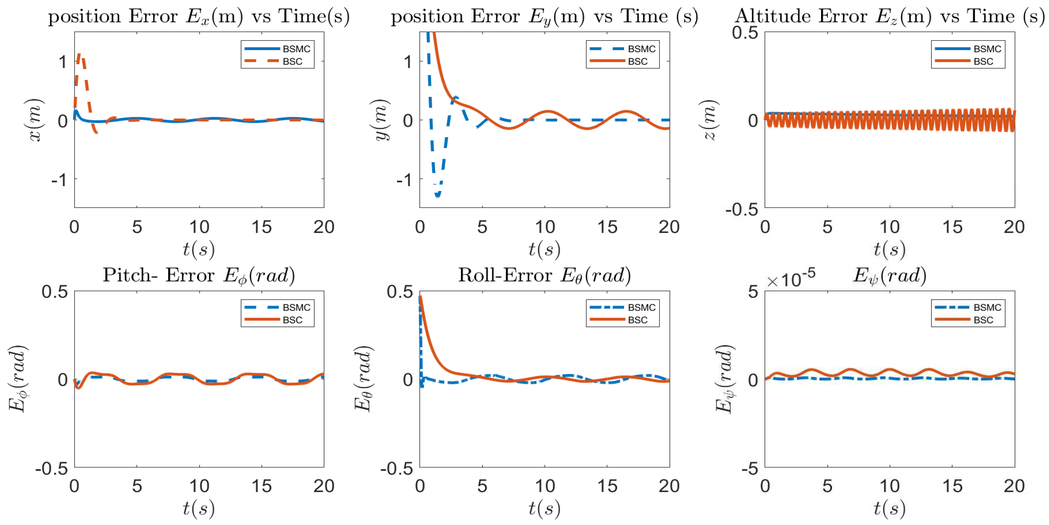
To evaluate the performance of the developed control algorithm, it is evaluated against BSC developed by [20,21]. The control error simulation results is as presented in Figure 5.

4.4. Results Interpretations

As presented in Figure 3, the developed PI control strategy for position control of servo arms shows a very good tracking performance with minimum deviations of 0.8 radian and 0.042 radian. This indicates the minimum and maximum deviations from all the morphing configurations. Also, maximum of 0.05 s settling time has been observed in all the investigated morphing configurations. Moreover, it can be observed from Figure 3, each morphing formation is resulting to centre of gravity and inertias ( I x x , I y y ) variations. This is due to the existence of geometric reformation and rotation angles along x y plane. The above stated variations are the basis for changes in system dynamics. It is essential to note that, the maximum and minimum overshoots of the servo arms are key parameters for morphing quadcopter motion planning in tight environment. The position and orientation results of Figure 4 show the ability of BSMC algorithm to adapt all sudden changes in dynamics and model uncertainty due to geometric reformation. It can also be concluded from the tracking performance of Figure 4 and control error of Figure 5 the ability of BSMC algorithm to successfully track the desired position x , y and z, and Euler angles ( ϕ , θ , ψ ) with minimum errors. Analysing the inset plots of Figure 5, and control error of Figure 5 there exist zero overshoot, fast convergence to stable neighbourhood hence, the closed loop system is stable. The 3D path visualization of Figure 6 shows the success of the proposed BSMC algorithm in tracking the desired path with a small error.

5. Conclusions

This research is on mathematical modelling of morphing quadcopter and development of robust backstepping sliding mode controller for position and orientation control. It has been established that, because of parameter variations, uncertainties and disturbances present in the morphing quadcopter model, controlling such kind of unconventional vehicles will be challenging and difficult. However, nonlinear robust control methods such as BSMC has been established as a suitable candidate solution. Though, the parametric variations of centre of gravity, inertias and allocation matrix imposes the change in system dynamics and affect the stability and control performance of the vehicle, the developed BSMC method managed to tracked the position and orientation with minimum deviation. To ascertain the performance of the developed BSMC, it is evaluated against the backstepping approach from the works of [20,21]. Overall, the obtained error results in both position and orientation Figure 5 show that the proposed BSMC strategy outperforms in terms of accuracy, deviation, and settling time. Therefore, this research has established the ability of the developed BSMC algorithm to control morphing quadcopter position and orientation even in the presence of parametric and nonparametric uncertainties.

Future Work

This research assumed and set control parameters to be constants however, in real scenario, these parameters are not constant but depend on the desired trajectory, its complexity and weather conditions. Also, the developed control algorithm has not been evaluated in the event of actuator failure, fault tolerance and trajectory tracking in unstructured environment. Therefore, future research will work on those limitations.

Author Contributions

Conceptualization, methodology and original draft preparation, I.A.S., validation and analysis, Z.H., project administration and software development M.B.A., review, editing and supervision M.B.M. and N.B.A. Latex programming and visualization, A.U. All authors have read and agreed to the published version of the manuscript.

Funding

This research received no external funding.

Informed Consent Statement

All authors have read and agreed to the published version of the manuscript.

Conflicts of Interest

The authors declare no conflict of interest.

References

  1. Shehu, I.A.; Mohammed, M.; Sulaiman, S.H.; Abdulkarim, A.; Alhassan, A.B. A Review on Unmanned Aerial Vehicle Energy Sources and Management. In International Conference on Emerging Applications and Technologies for Industry 4.0 (EATI’2020); Abawajy, J.H., Choo, K.K.R., Chiroma, H., Eds.; Lecture Notes in Networks and Systems; Springer: Cham, Switzerland, 2021; Volume 254. [Google Scholar] [CrossRef]
  2. Tothong, T.; Samawi, J.; Govalkar, A.; George, K. Morphing Quadcopters: A Comparison Between Proposed and Prominent Foldable Quadcopters. In Proceedings of the 2020 11th IEEE Annual Information Technology, Electronics and Mobile Communication Conference (IEMCON), Vancouver, BC, Canada, 4–7 November 2020; pp. 0589–0596. [Google Scholar]
  3. Hoffmann, K.A.; Chen, T.G.; Cutkosky, M.R.; Lentink, D. Bird-inspired robotics principles as a framework for developing smart aerospace materials. J. Compos. Mater. 2023, 57, 679–710. [Google Scholar] [CrossRef]
  4. Floreano, D.; Mintchev, S.; Shintake, J. Foldable drones: From biology to technology. Bioinspir. Biomimetics Bioreplication 2017, 10162, 1016203. [Google Scholar]
  5. Falanga, D.; Kleber, K.; Mintchev, S.; Floreano, D.; Scaramuzza, D. The foldable drone: A morphing quadrotor that can squeeze and fly. IEEE Robot. Autom. Lett. 2018, 4, 209–216. [Google Scholar] [CrossRef]
  6. Belmouhoub, A.; Bouzid, Y.; Medjmadj, S.; Hocine Derrouaoui, S.; Guiatni, M. Backstepping control merged with disturbances observer for quadrotor with rotating arms. J. Unmanned Syst. 2024, 12, 61–74. [Google Scholar] [CrossRef]
  7. Derrouaoui, S.H.; Bouzid, Y.; Guiatni, M. Nonlinear robust control of a new reconfigurable unmanned aerial vehicle. Robotics 2021, 10, 76. [Google Scholar] [CrossRef]
  8. Bucki, N.; Mueller, M.W. Design and control of a passively morphing quadcopter. In Proceedings of the 2019 International Conference on Robotics and Automation (ICRA), Montreal, QC, Canada, 20–24 May 2019; pp. 9116–9122. [Google Scholar]
  9. Nemati, A. Designing, Modeling and Control of a Tilting Rotor Quadcopter. Doctoral Dissertation, University of Cincinnati, Cincinnati, OH, USA, 2016. [Google Scholar]
  10. Riviere, V.; Manecy, A.; Viollet, S. Agile robotic fliers: A morphing-based approach. Soft Robot. 2018, 5, 541–553. [Google Scholar] [CrossRef] [PubMed]
  11. Zhao, N.; Luo, Y.; Deng, H.; Shen, Y. The deformable quad-rotor: Design, kinematics and dynamics characterization, and flight performance validation. In Proceedings of the 2017 IEEE/RSJ International Conference on Intelligent Robots and Systems (IROS), Vancouver, BC, Canada, 24–28 September 2017; pp. 2391–2396. [Google Scholar]
  12. Desbiez, A.; Expert, F.; Boyron, M.; Diperi, J.; Viollet, S.; Ruffier, F. X-Morf: A crash-separable quadrotor that morfs its X-geometry in flight. In Proceedings of the 2017 Workshop on Research, Education and Development of Unmanned Aerial Systems (RED-UAS), Linköping, Sweden, 3–5 October 2017; pp. 222–227. [Google Scholar]
  13. Brown, L.; Clarke, R.; Akbari, A.; Bhandari, U.; Bernardini, S.; Chhabra, P.; Marjanovic, O.; Richardson, T.; Watson, S. The design of prometheus: A reconfigurable uav for subterranean mine inspection. Robotics 2020, 9, 95. [Google Scholar] [CrossRef]
  14. Papadimitriou, A.; Mansouri, S.S.; Kanellakis, C.; Nikolakopoulos, G. Geometry aware nmpc scheme for morphing quadrotor navigation in restricted entrances. arXiv 2021, arXiv:2101.02965. [Google Scholar]
  15. Wallace, D.A. Dynamics and Control of a Quadrotor with Active Geometric Morphing. Master’s Thesis, University of Washington, Washington, DC, USA, 2016. Available online: http://hdl.handle.net/1773/35518 (accessed on 1 January 2025).
  16. Derrouaoui, S.H.; Bouzid, Y.; Belmouhoub, A.; Guiatni, M. Enhanced nonlinear adaptive control of a novel over-actuated reconfigurable quadcopter. In Proceedings of the 2023 International Conference on Unmanned Aircraft Systems (ICUAS), Warsaw, Poland, 6–9 June 2023; pp. 229–234. [Google Scholar]
  17. Ryll, M.; Bülthoff, H.H.; Giordano, P.R. First flight tests for a quadrotor UAV with tilting propellers. In Proceedings of the 2013 IEEE International Conference on Robotics and Automation, Karlsruhe, Germany, 6–10 May 2013; pp. 295–302. [Google Scholar]
  18. Hintz, C.; Torno, C.; Carrillo, L.R.G. Design and dynamic modeling of a rotary wing aircraft with morphing capabilities. In Proceedings of the 2014 International Conference on Unmanned Aircraft Systems (ICUAS), Orlando, FL, USA, 27–30 May 2014; pp. 492–498. [Google Scholar]
  19. Zhao, M.; Anzai, T.; Shi, F.; Chen, X.; Okada, K.; Inaba, M. Design, modeling, and control of an aerial robot dragon: A dual-rotor-embedded multilink robot with the ability of multi-degree-of-freedom aerial transformation. IEEE Robot. Autom. Lett. 2018, 3, 1176–1183. [Google Scholar] [CrossRef]
  20. Belmouhoub, A.; Medjmadj, S.; Bouzid, Y.; Derrouaoui, S.H.; Guiatni, M. Enhanced backstepping control for an unconventional quadrotor under external disturbances. Aeronaut. J. 2023, 127, 627–650. [Google Scholar] [CrossRef]
  21. Derrouaoui, S.H.; Bouzid, Y.; Guiatni, M. PSO based optimal gain scheduling backstepping flight controller design for a transformable quadrotor. J. Intell. Robot. Syst. 2021, 102, 67. [Google Scholar] [CrossRef]
  22. Darvishpoor, S.; Roshanian, J.; Raissi, A.; Hassanalian, M. Configurations, flight mechanisms, and applications of unmanned aerial systems: A review. Prog. Aerosp. Sci. 2020, 121, 100694. [Google Scholar] [CrossRef]
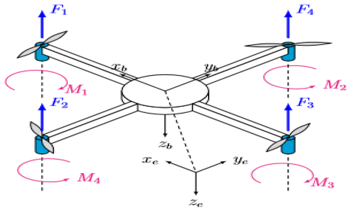
Figure 1. Quadcopter Model.
Engproc 87 00086 g001
Figure 2. Control Structure.
Engproc 87 00086 g002
Figure 3. Servo Tracking, Inertia and CG Variations.
Engproc 87 00086 g003
Figure 4. Position and Orientation Control.
Engproc 87 00086 g004
Figure 5. BSMC and BSC Control error Performance Evaluation for position and Orientation.
Engproc 87 00086 g005
Figure 6. 3D Spiral Trajectory Performance Evaluation.
Engproc 87 00086 g006
Table 1. Morphing Configurations.
S/N σ 1 σ 2 σ 3 σ 4 Configuration
1 π 4 π 4 π 4 π 4 X
2 π 2 0 π 2 0H
3 π 4 π 4 π 2 0Y
40 π 2 π 2 0T
5 π π π π O
Disclaimer/Publisher’s Note: The statements, opinions and data contained in all publications are solely those of the individual author(s) and contributor(s) and not of MDPI and/or the editor(s). MDPI and/or the editor(s) disclaim responsibility for any injury to people or property resulting from any ideas, methods, instructions or products referred to in the content.