Abstract
The beam–column connection is an important element in frame construction. Despite numerous studies, there is still no uniform procedure for shear force design across countries. We continue to witness serious problems and even collapse of buildings under seismic activity caused by failures in the beam–column connection of the frame. During the last 60 decades, a large number of experimental studies have been carried out on frame assemblies, where various parameters and their compatibility under cyclic activities have been investigated. What remains misunderstood is the magnitude and distribution of the forces passing through the joint and their involvement in the magnitude of the shear force. Here, the creation of a new mathematical model for the beam and column contributes significantly to our understanding of the flow of forces in the frame connection. For this purpose, the full dimensions of the beam and its material properties are taken into account. All investigations were carried out before crack initiation and after crack propagation along the face of the column, where it separates from the beam. In the present work, the beam is subjected to two symmetrical, transverse, uniformly distributed loads. Expressions are derived to determine the magnitudes of the support reactions from the beam, as a function of the height of its lateral edge. The load positions corresponding to the extreme values of the support reactions are determined. Numerical results are presented for the effect over the magnitudes of the support reactions from different strengths of concrete and steel on the beam. The results are compared with those given in the Eurocode for shear force calculation. It is found that the shear force determined by the proposed new model exceeds the force calculated by Eurocode by 4–62.5%, depending on the crack development stage and the beam materials.
1. Introduction
The transfer of forces in framed structures from beams to columns under dynamic loads can threaten the integrity of the connection. Determining the shear force in the connection continues to preoccupy researchers.
The first definition of shear force in a joint was given in [1] by Hanson and Connor (1967) as the horizontal force acting at the mid-height of the beam–column connection. Experimental and analytical studies conducted since the introduction of this definition have observed the influence of various variables on the response of the beam–column joint [2,3,4,5,6,7,8,9,10,11].
In Eurocode 8 [12], the beam forces contributing to the shear force are determined based on capacity design. These are the forces absorbed by the longitudinal reinforcing bars when the steel yields. The same assumption is also made in [13]. Nowadays, capacity design methods give additional consideration to the involvement of the concrete section and stirrups in the joint [14,15,16]. In [17], a graphical method called monograms is proposed to determine the geometric dimensions of the beam–column connection and the number of stirrups. In [18], the experimental results are compared with a 3D model, allowing the researchers to vary the characteristics of the construction materials used.
However, all these approaches do not answer the question of how large the shear force actually is. In [19,20,21,22,23], a beam and cantilever model is proposed to determine the magnitude of the shear force by considering the contribution of the concrete section, the beam dimensions, and the material characteristics of the constituent members. In this study, the forces transferred from the beam are determined as a result of two symmetrical, uniformly distributed loads. Determining the exact expressions of the beam’s forces before the beam–column connection allows the exact magnitude of the shear force to be calculated. The appearance of a crack between the beam and the column and its growth allows us to track the change in shear force in a limit stage. The results obtained for the magnitude of the shear force are compared with those given in the literature and prescribed in Eurocode 8 (2004) [12].
2. Materials
In their study [1], Hanson and Connor defined the shear force in an internal beam–column connection from Figure 1, by Equation (1).
where and are the compressive forces in concrete and in the longitudinal reinforcing bars in the beam passing through the connection; and are the tensile forces in the longitudinal reinforcing bars in the beam; and is the shear force of the column.
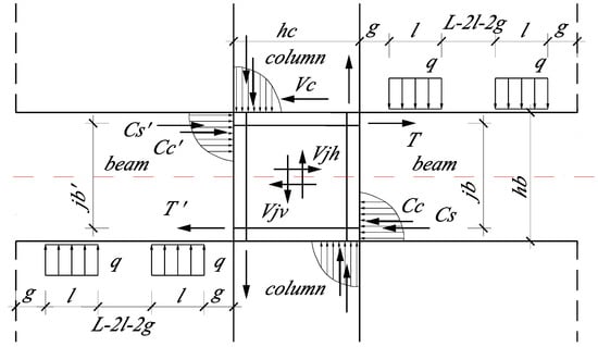
Figure 1.
Joint shear force: is the force transferred at the mid-height of a horizontal section (the red line), in an RC beam–column connection.
The difficulty encountered in determining the forces and from Equation (1) leads to the adoption in the literature of:
where and are the moments at the column face and and are the lever arms corresponding to these moments. The lever arms are assumed to remain constant during the deformation process.
In this article, the following tasks are set: 1. To derive expressions for the forces from Figure 1 and from Equation (1); 2. To use the derived expressions to calculate the forces for selected sections and determine the magnitude of the shear force; 3. To compare the resulting shear force values with those prescribed in Equation (2) and in Eurocode 8 [12]; 4. To investigate how much the magnitude of shear force changes when the material characteristics of some sections are changed.
3. Method
3.1. Support Reactions with Axial Force in the Strain Energy Expression
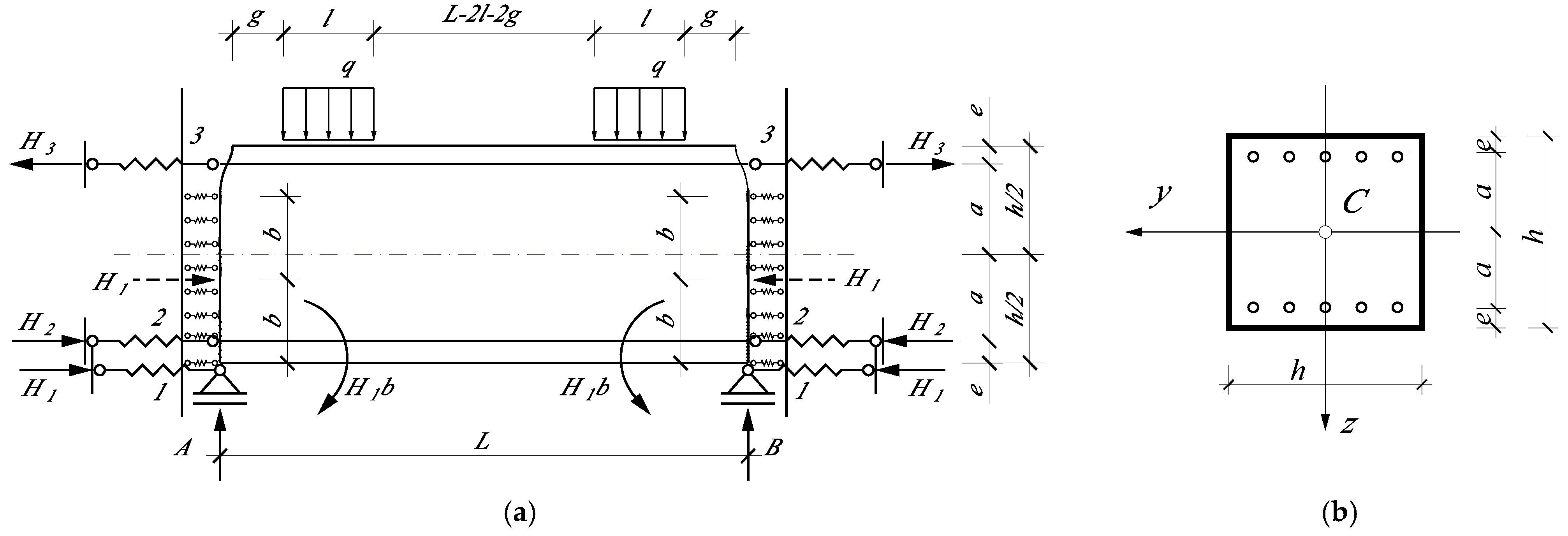
A frame structure beam is considered below. The beam is statically indeterminate, prismatic, and symmetrical. The beam is subjected to special bending and tension/compression, and the Bernoulli–Euler hypothesis is applied (Figure 2).
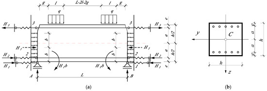
Figure 2.
Mathematical model of the beam; (a) Supports of a “simple” beam–column connection; (b) Cross-section of the beam: symmetrical.
The solution is based on Menabria’s theorem for statically indeterminate systems in first-order theory.
The potential energy of deformation in special bending, combined with tension (compression) and with the effects of linear springs taken into account, is as follows:
where is the bending moment in particular sections;
is the axial force of the beam;
is the support reaction at support 1, corresponding to a spring with a spring constant of . It is set as the reduced tensile/compressive stiffness of the concrete section by the multiplier ;
In supports 2 and 3, the support reactions and occur. The corresponding springs have spring constants and . They are set as the reduced tensile/compressive stiffness of the steel section by the multiplier and ;
is the length of the beam;
, , and are the tensile (compressive) stiffness of the concrete cross-section and the reinforcing bars, respectively;
, , and are the bending stiffness of the concrete cross-section and the reinforcing bars, respectively;
are the tensile (compressive) stiffness of the composite section;
are the bending stiffness of the composite section.
It is a well-known fact that, according to Menabria’s theorem, the desired hyperstatic unknown is determined by the condition of minimum potential energy with respect to it, or:
A mathematical model of a beam with a symmetrical cross-section is given in Figure 2a. The cross-section of the beam is shown in Figure 2b.
The equilibrium conditions of statics give, respectively:
The axial force and bending moment for the individual sections of the beam are substituted into Equation (3). We apply the solution according to Equation (4). The resulting horizontal support reactions are, respectively:
3.2. Support Reactions Without Axial Force in Strain Energy Expression
Neglecting the axial force in the strain potential energy expression, the support reactions become:
Introducing and into Equations (6) and (8) leads to the equations for a beam loaded uniformly along its entire length, based on [24,25].
The solution was performed in the symbolic environment of MATLAB R2017b [26].
4. Results and Discussion
For the numerical results, a beam with a cross-section of was introduced. The transverse load is with ; , , and . The distance varies in the interval and is monitored by the ratio . The length of the beam is .
When we consider rigid support between structural elements through the static schemes, we assume that the connections between them do not allow the sections to move or rotate. The rigid support has a larger , and from there, a larger . It was shown in [19] that it can be assumed with sufficient accuracy that and . Three examples are considered, each with a different moduli of elasticity for concrete and steel. The first example, Case I, is calculated with moduli of elasticity and . The second example, Case II, is for moduli of elasticity and [27]. The third example, Case III, is for and .
4.1. Comparison of Support Reaction Magnitude Results for Case I, Case II, and Case III
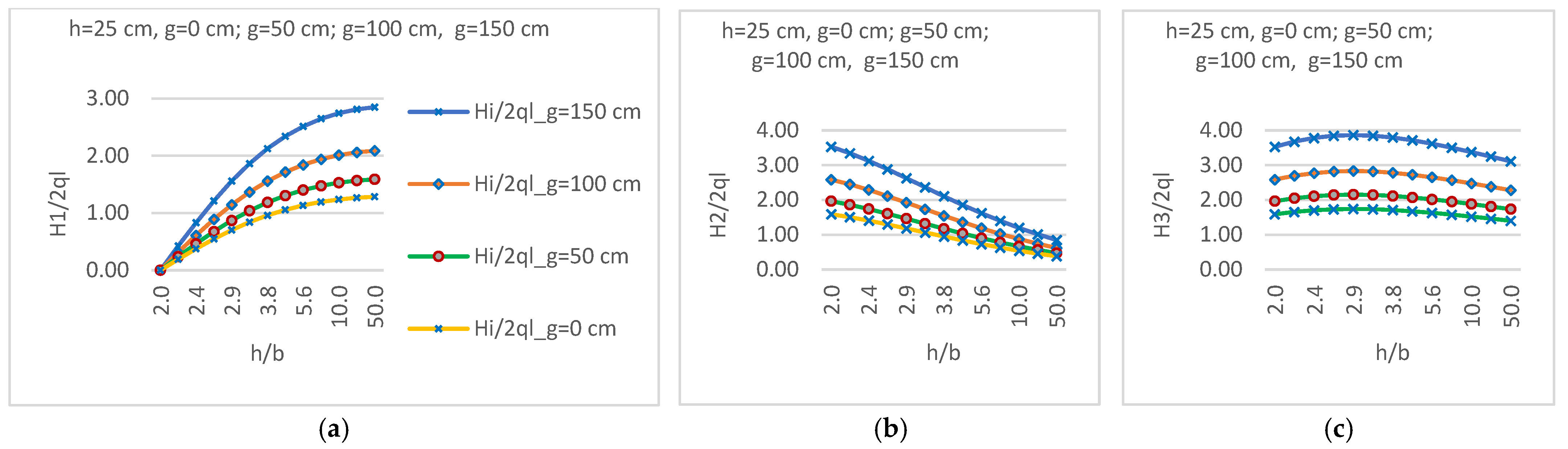
It can be seen from Figure 3 that the movement of the uniformly distributed loads towards the mid-section of the beam, with an increase of , leads to an increase in the magnitudes of the three support reactions. The growth of the crack between the beam and the column also leads to an increase in the support reaction and a decrease in the support reaction , while the support reaction increases to , and then decreases. This is observed in all three examples considered. The percentage differences in the magnitudes of the three support reactions for some characteristic values of for the three examples are shown in Table 1.
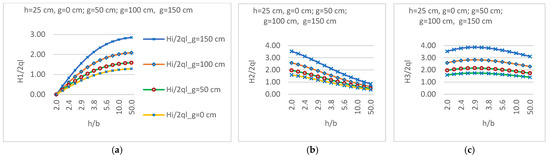
Figure 3.
Parameters of the three support reactions with variations in distance g and with an increase in the crack on the face of the column for Case I; (a) H1/2ql; (b) H2/2ql; (c) H3/2ql.

Table 1.
Percentage differences in the magnitudes of the three support reactions for the three examples.
The results in Table 1 are for and show that as the concrete modulus increases, the support reaction increases, and the support reactions and decrease. Larger steel moduli and lead to a decrease in and an increase in and .
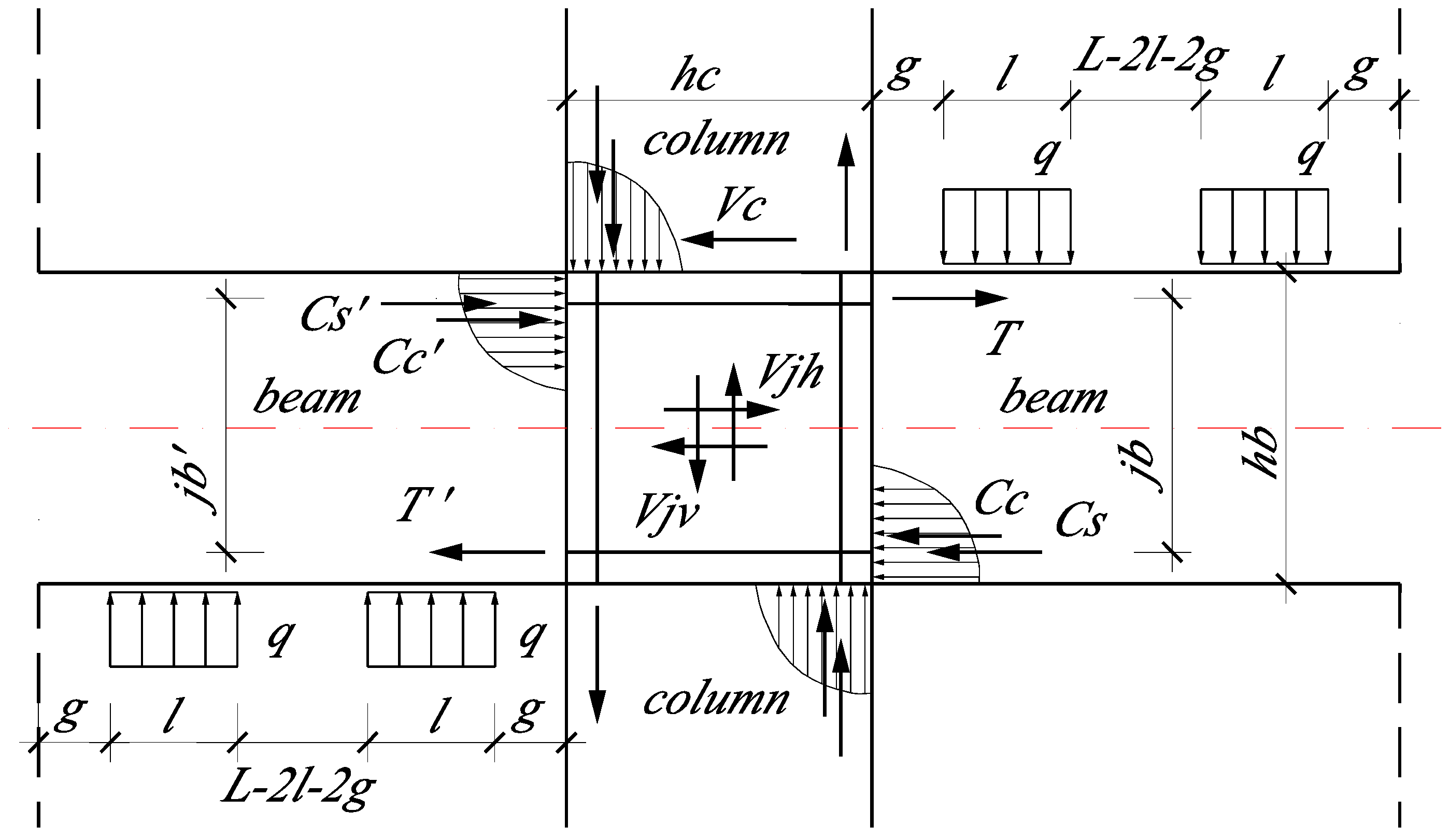
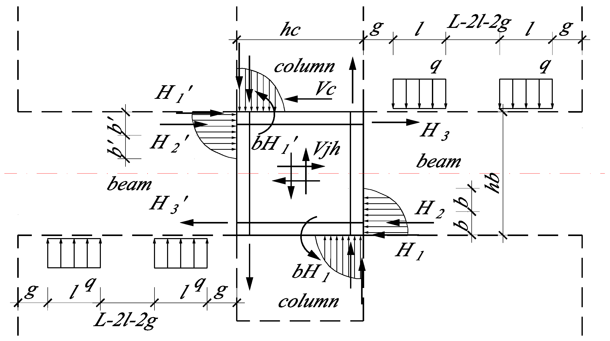
A model to determine the shear force in an RC interior beam–column connection is proposed on Figure 4.
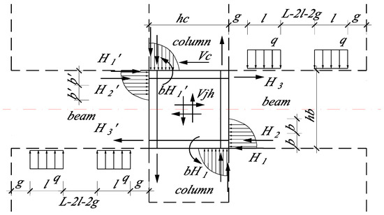
Figure 4.
Definition of joint shear force in interior RC beam–column connection. Distribution of forces.
If the frame is symmetrical and all other conditions being equal, we have equality for , , and . Then (9) becomes:
4.2. Comparison of the Results from Equation (2), Equation (10), and Eurocode
The values of were determined using the RuckZuck 4.0 software [28]. The beam has two rigid supports.
All results are converted into parametric form by dividing the load by 2ql.
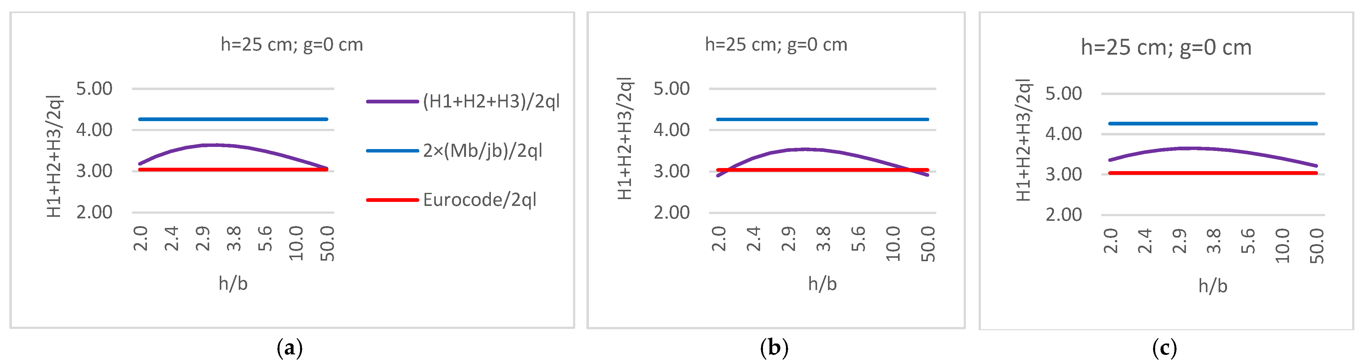
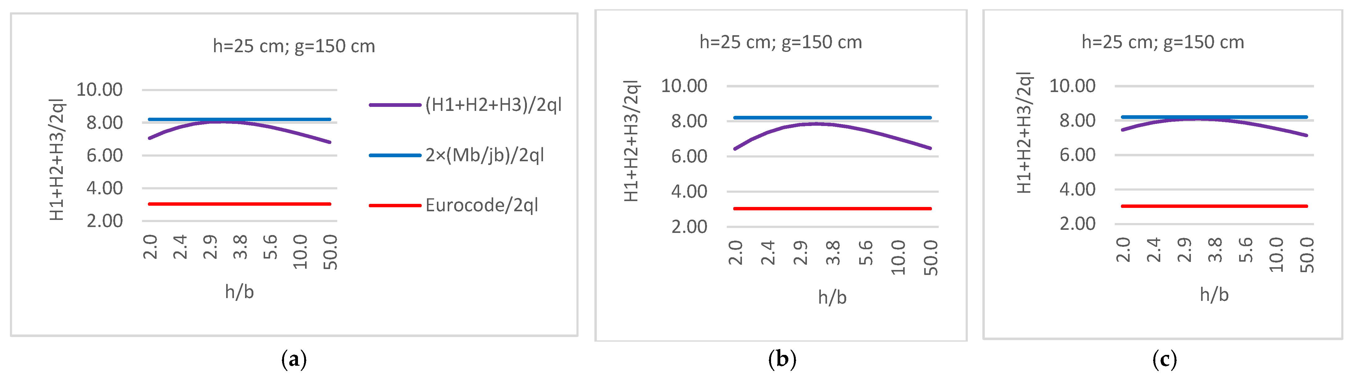
Figure 5 and Figure 6 provide information about the increase in shear force with the change in distance . For the specific material values, the magnitude of significantly exceeds the Eurocode limit. The percentage differences for the three considered examples at are shown in Table 2.
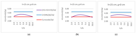
Figure 5.
Comparison of the parameters of the three support reactions for distance g = 0 cm with Equation (2) and Eurocode for the three examples (a) Case I; (b) Case II; (c) Case III.
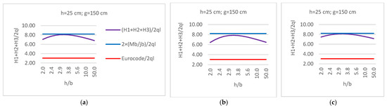
Figure 6.
Comparison of the parameters of the three support reactions for distance g = 150 cm with Equation (2) and Eurocode for the three examples (a) Case I; (b) Case II; (c) Case III.
Table 2.
Comparison of the parameters of the three support reactions for distance g = 150 cm with Equation (2) and with Eurocode.
5. Conclusions
The expressions for the horizontal support reactions for the beam of a frame structure with two uniformly distributed loads are derived. The obtained forces are used to calculate the shear force in the beam–column connection. The method allows us to take into account the participation of the concrete cross-section in the total magnitude of the shear force. The dimensions of the beam and the material characteristics of the composite elements are also taken into account and have an impact on the shear force. The expressions allow us to select different combinations of data and to calculate the shear force as it is at the specific load. Joint designs should be carried out based on these determined forces.
Funding
This research received no external funding.
Institutional Review Board Statement
Not applicable.
Informed Consent Statement
Not applicable.
Data Availability Statement
The data presented in this study are available upon request from the corresponding author.
Conflicts of Interest
The author declares no conflicts of interest.
References
- Hanson, N.W.; Connor, H.W. Seismic Resistance of Reinforced Concrete Beam-Column Joint. J. Struct. Div. 1967, 93, 533–560. [Google Scholar] [CrossRef]
- Park, R.; Keong, Y.S. Test on structural concrete beam-column joints with intermediate column bars. Bull. New Zealand Natl. Soc. Earthq. Eng. 1979, 12, 189–203. [Google Scholar] [CrossRef]
- Paulay, T. Equilibrium criteria for reinforced-concrete beam-column joints. ACI Struct J. 1989, 86, 635–643. [Google Scholar]
- Park, R. A Summary of Results of Simulated Seismic Load Tests on Reinforced Concrete Beam-Column Joints, Beams and Columns with Substandard Reinforcing Details. J. Earthq. Eng. 2002, 6, 147–174. [Google Scholar] [CrossRef]
- Javad, S.; Bengar, H.A.; Parvin, A. Analytical prediction of seismic behavior of RC joints and columns under varying axial load. Eng. Struct. 2018, 174, 792–813. [Google Scholar] [CrossRef]
- Gombosuren, D.; Maki, T. Prediction of Joint Shear Deformation Index of RC Beam–Column Joints. Buildings 2020, 10, 176. [Google Scholar] [CrossRef]
- Hayat, K.F.; Tahir, M.F.; Khan, Q.Z. Numerical simulation and performance evaluation of beam column joints containing FRP bars and wire mesh arrangements. J. Mech. Contin. Math. Sci. 2021, 16, 112–130. [Google Scholar] [CrossRef]
- Kalogeropoulos, G.; Tsonos, A.-D.; Iakovidis, P. Hysteresis Behavior of RC Beam–Column Joints of Existing Substandard RC Structures Subjected to Seismic Loading–Experimental and Analytical Investigation. Buildings 2024, 14, 1609. [Google Scholar] [CrossRef]
- Kim, J.; LaFave, J.M. Key infuence parameters for the joint shear behaviour of reinforced concrete (RC) beam–column connections. Eng. Struct. 2007, 29, 2523–2539. [Google Scholar] [CrossRef]
- Shafaei, J.; Zareian, M.S.; Hosseini, A.; Marefat, M.S. Effects of joint flexibility on lateral response of reinforced concrete frames. Eng. Struct. 2014, 81, 412–413. [Google Scholar] [CrossRef]
- Ramaglia, G.; Lignola, G.P.; Fabbrocino, F.; Prota, A. Unified Simplified Capacity Model for Beam-Column Joints into RC Moment Resisting Frame. Appl. Sci. 2022, 12, 10709. [Google Scholar] [CrossRef]
- EN 1998-1; Eurocode 8: Design of Structures for Earthquake Resistance-Part 1: General Rules, Seismic Actions and Rules for Buildings. European Committee for Standardization: Brussels, Belgium, 2004; Volume 1, p. 231.
- Barbagallo, F.; Bosco, M.; Ghersi, A.; Marino, E.M.; Sciacca, F. A simple but effective capacity model for check and design of beam-column joints in RC seismic buildings. Procedia Struct. Integr. 2023, 44, 363–370. [Google Scholar] [CrossRef]
- Shiohara, H. New model for shear failure of RC interior beam-column connection. J. Struct. Eng. 2001, 127, 152–160. [Google Scholar] [CrossRef]
- Fardis, M.N. Shear strength model for RC joints, consistent with the shear design rules for prismatic members in the second-generation Eurocodes. Bull Earthq. Eng 2021, 19, 889–917. [Google Scholar] [CrossRef]
- Floridia, A.; Panarelli, D.; Rossi, P.P.; Spinella, N. Simplified evaluation of the shear strength of slender rectangular R.C. members with shear reinforcement. Procedia Struct. Integr. 2023, 44, 504–511. [Google Scholar] [CrossRef]
- Nicoletti, V.; Carbonari, S.; Gara, F. Beam-column joint nomogram: A simple and fast-to-use tool to evaluate the joint integrity in RC structures. Procedia Struct. Integr. 2023, 44, 371–377. [Google Scholar] [CrossRef]
- Angiolilli, M.; Gregori, A.; Tonelli, R.; Tonelli, C.; Ciuffetelli, E.; Peditto, A. Structural performance of unreinforced full-scale façade concrete beam-column joint under cyclic load. Procedia Struct. Integr. 2023, 44, 870–877. [Google Scholar] [CrossRef]
- Doicheva, A. Shear Force of Interior Beam–Column Joints under Symmetrical Loading with Two Transverse Forces on the Beam. Buildings 2024, 14, 3028. [Google Scholar] [CrossRef]
- Doicheva, A. Determination of the Shear Force in RC Interior Beam-Column Connections. Eurasia Proc. Sci. Technol. Eng. Math. 2023, 23, 361–371. [Google Scholar] [CrossRef]
- Doicheva, A. Distribution of Forces in RC Interior Beam–Column Connections. Eng. Proc. 2023, 56, 114. [Google Scholar] [CrossRef]
- Doicheva, A. Shear force in RC internal beam-column connections for a beam loaded with a transverse force occupying different possible positions. Eurasia Proc. Sci. Technol. Eng. Math. (EPSTEM) 2024, 29, 128–144. [Google Scholar] [CrossRef]
- Doicheva, A. Alteration of the Shear Force in an Internal Beam-Column Joint during the Initiation and Growth of a Crack in a Cantilever Beam. Procedia Struct. Integr. 2024, 66, 433–448. [Google Scholar] [CrossRef]
- Doicheva, A. Off-center supported beam with additional elastic supports, located along the height of the beam and loaded with a distributed transverse load. In Proceedings of the XXIII International Scientific Conference VSU’2023, Sofia, Bulgaria, 22–24 June 2023; Volume I, pp. 451–460. (In Bulgarian). [Google Scholar]
- Doicheva, A. Determination of Forces in an Internal Beam-Column Connection. Static Research; Dinev, D., Abdulahad, E., Eds.; Avangard Prima: Sofia, Bulgaria, 2024; p. 152. [Google Scholar]
- MATLAB, R2017b. The MathWorks Inc.: Natick, MA, USA, 2017.
- Doicheva, A.; Shu, Y.; Kusuhara, F.; Shiohara, H. Seismic tests on reinforced concrete beam-column joint sub-assemblages subject to lateral and long-term vertical load. Struct. Integr. Life 2023, 23, 269–276. [Google Scholar]
- RuckZuck, Version 4.0. Mursoft Wörgötter, Kump OEG: Graz, Austria, 2015.
Disclaimer/Publisher’s Note: The statements, opinions and data contained in all publications are solely those of the individual author(s) and contributor(s) and not of MDPI and/or the editor(s). MDPI and/or the editor(s) disclaim responsibility for any injury to people or property resulting from any ideas, methods, instructions or products referred to in the content. |
© 2025 by the author. Licensee MDPI, Basel, Switzerland. This article is an open access article distributed under the terms and conditions of the Creative Commons Attribution (CC BY) license (https://creativecommons.org/licenses/by/4.0/).