Abstract
Electric vehicles are replacing conventional vehicles in today’s world due to their eco-friendly operation and reduced maintenance. Although EVs offer advantages over conventional vehicles, there is a limited number of charging stations, and numerous power quality issues have emerged at these locations. This is due to the voltage, current, or frequencies being abnormal, which leads to sudden voltage drops, voltage swells, long interruptions, and short interruptions occurring at the charging stations. To address issues arising from client-side anomalies, we attach conventional FACTS devices closer to the load end. One such dependable custom power gadget for dealing with voltage sag is the one developed in this article, and it is called an enhanced dynamic voltage restorer (DVR). The proposed device continuously monitors the load voltage waveform and injects (or absorbs) the balance (or surplus) voltage into (or away from) the load voltage whenever a sag occurs. We develop a reference voltage waveform to achieve the aforementioned capabilities. In this paper, the methods of compensation for these problems at charging stations are discussed. Furthermore, the power quality problems are compensated for by the proposed system using an SVPWM controller. Simulation and real-time implementation are carried out, and the results are discussed. The inclusion of SVPWM control significantly improves voltage regulation and reduces THD by 60–70% compared to conventional PWM methods, which achieve only 40–50% reduction. The proposed DVR is designed for single-phase applications, making it suitable for low-voltage distribution systems and sensitive industrial loads. The proposed model provides a rapid response time (<10 ms), and the efficiency of the proposed DVR is found to be 92%, which is greater than that of conventional designs (86%).
1. Introduction
Electric vehicles (EVs) are revolutionizing the transportation business by offering a cleaner and more environmentally friendly alternative to traditional gasoline-powered cars. Unlike traditional automobiles that use internal combustion engines, EVs run on electric motors powered by rechargeable batteries. This method greatly reduces carbon emissions, reduces air pollution, and helps to save fossil fuel resources. Moreover, EVs have fewer moving components, which reduces maintenance costs and improves reliability. However, as EV usage grows, specific issues emerge, notably at charging stations. These stations, which are critical for EV operation, typically experience power quality problems such as voltage sags, harmonics, and fluctuations.
These disturbances can reduce charging efficiency, damage sensitive EV components such as battery systems and motor windings, and shorten the vehicle’s overall lifespan. Ensuring power quality at charging stations is critical for the reliable and efficient operation of EVs. Power quality issues in EV charging infrastructure impact charging efficiency and grid stability due to voltage sags and harmonic distortions [1]. While DVRs are commonly used for voltage sag mitigation, most applications focus on general power quality improvements without implementing real-time DVR-based compensation for EV stations [2]. In addition to charging stations, power transmission networks experience voltage fluctuations due to load variations and disturbances during power transfer, which can be mitigated using FACTS devices [3]. However, these solutions do not directly address DVR-based voltage sag compensation. The dynamic voltage restorer (DVR), consisting of inverters, transformers, and filters, is widely used to stabilize power transmission [3].
Several DVR control strategies have been explored to improve system performance. AC-AC converter-based DVRs eliminate the need for a DC link, making them suitable for weak grids, but they lack harmonic suppression and transient response optimization [4]. The synchronous reference frame (SRF)-based DVR control technique improves accuracy and speed but does not fully eliminate harmonics, which is critical for power-sensitive applications [5]. The impact of voltage sags on grid-fed EV charging stations has been analyzed to understand how voltage disturbances affect charging efficiency and grid stability [6]. While this study identifies the problem and discusses possible mitigation strategies, it does not propose an active compensation technique like DVR. Additionally, it lacks real-time transient response optimization and harmonic suppression, which are crucial for ensuring a stable EV charging environment. Unlike this approach, the proposed system integrates DVR-based voltage compensation, improving voltage stability and power quality for EV charging stations. Further research has examined fault ride-through (FRT) in hybrid grids, but without direct DVR-based compensation [7].
Voltage sag detection techniques have been proposed, yet most focus on monitoring rather than active mitigation [8]. DVR integration into EV fast-charging stations has been studied, but the transient response and harmonic suppression remain un-optimized [9]. Improved DVR strategies exist for voltage sag duration, yet real-time response and harmonic filtering have not yet been fully addressed [10].
In addition to overcoming these problems, the increasing use of EVs emphasizes the importance of incorporating renewable energy sources, such as solar and wind, into charging infrastructure. This strategy not only decreases reliance on the grid, but it also promotes global sustainability. However, renewable energy sources are inherently intermittent, which might result in significant changes in power quality. Advanced energy storage solutions, such as high-capacity batteries and super capacitors, are being investigated to offset these changes. Thus, a novel DVR is proposed with the following features:
- Blending of an injection transformer improves voltage compensation efficiency while maintaining a compact design.
- Also, the inclusion of SVPWM control significantly improves voltage regulation and reduces THD by 60–70% compared to conventional PWM methods, which achieve only 40–50% reduction.
- The SVPWM method enhances DC bus utilization and maintains a consistent switching frequency, which leads to improved inverter performance and efficiency.
- The proposed DVR is designed for single-phase applications, making it suitable for low-voltage distribution systems and sensitive industrial loads.
- The proposed model provides a rapid response time (<10 ms), ensuring effective compensation for voltage sags and swells in real-time applications.
- The efficiency of the proposed DVR is 92%, which is greater than that of conventional designs (86%); thus, it shows improved energy utilization.
- The DVR is simulated in MATLAB and tested for real-time operation.
2. Power Quality Problems
Here, the concerns regarding a utility provider’s ability to deliver a reliable electrical supply are outlined. The quality of electric power is affected by “supply continuity, voltage magnitude change, transients, and harmonic content in electrical signals” as discussed in Table 1. In order for electrical systems to perform properly and without failure, electrical quantities must be synchronized.

Table 1.
Power quality specifications.
Voltage drop is a major power quality concern in electrical systems (Figure 1). A custom power device can be connected to the load to correct voltage sags and safeguard sensitive equipment.
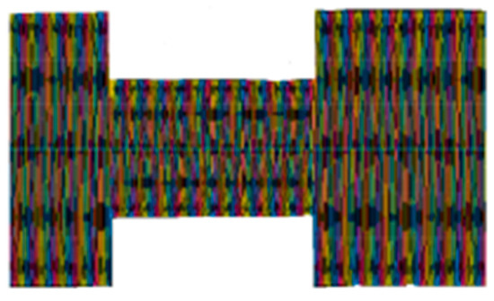
Figure 1.
Voltage sag waveform.
As shown in Figure 2, a voltage swell refers to a rapid increase in RMS voltage of 10% or more above the specified range for equipment, persisting for duration between half a cycle and one minute, contrasting with voltage sags. Voltage bulges are more perplexing and frequently associated with structural problem situations than voltage sags (plunges). This can happen when a specific line to ground shortage is balanced, which will raise the voltage level to different stages quickly, as shown in the model below. This will undoubtedly happen in ungrounded or floating ground delta structures. Increases in voltage level can also happen when an large weight is removed.
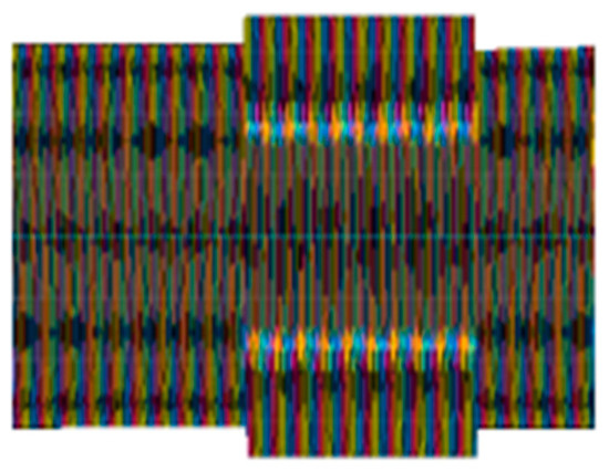
Figure 2.
Voltage swell waveform.
3. Proposed DVR System for Power Utility
As illustrated in Figure 3, a dynamic voltage restorer (DVR) consists of power electronic components such as transformers, voltage source inverters, PWM controllers, and passive filters. It enhances grid voltage using an injection transformer, where the primary winding connects to the inverter and the secondary winding links to the grid output. A DC link capacitor supplies DC voltage, which the inverter converts to AC using four MOSFET switches. LC filters smooth the inverter’s AC output before delivering it to the injection transformer. The inverter operates using Space Vector Pulse Width Modulation (SVPWM) to ensure precise and efficient performance.
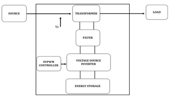
Figure 3.
Schematic representation of DVR.
Space Vector Pulse Width Modulation is an improved version of PWM and SPWM. SVPWM operates on the premise of “when the upper transistor is switched on, the corresponding lower transistor is switched off” as shown in Figure 4. At present, most of the power system uses 3-phase voltage sources. SVPWM is the most efficient and reliable control method for the effective usage of voltage and reducing the harmonics in the output. It is used to generate AC waveforms, with SVPWM providing benefits over other control methods, including a consistent switching frequency, lower harmonic distortion, and improved DC bus utilization. This technique can also increase output voltage by up to 15% compared to other approaches.
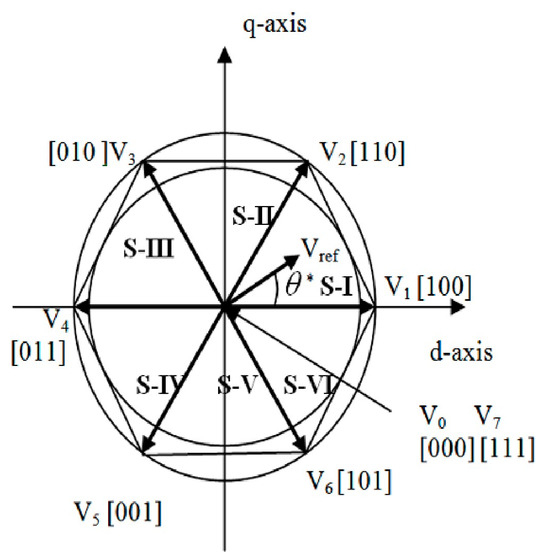
Figure 4.
Vector representation of switching gates.
SVPWM Control Algorithm Derivation:
The first step in SVPWM is transforming the three-phase voltage components(D,E,F) into a two-dimensional d-q reference frame using Clarke transformation:
where
- represents the projection along the horizontal axis (d-axis);
- represents the projection along the vertical axis (q-axis);
- This transformation simplifies PWM control and helps determine the sector location of
Using the transformed components, the magnitude of the reference voltage is
The angle θ (which determines the sector position) is
where
- The reference vector points towards the desired output voltage;
- determines in which sector (S-I to S-VI) the reference vector is located.
From the space vector diagram, the d-q plane is divided into six active vector sectors. To approximate the reference vector, the nearest two active vectors in the sector are selected for switching:
where
- T1 and T2 are the two active vectors;
- T0 represents the zero vector time, used to balance switching cycles;
- Ts is the switching period;
- Vdc is the DC-link voltage.
DVR Compensation Strategy:
Voltage sag occurs when the supply voltage falls below the nominal level:
DSAG = DNOM − DLOAD
To restore nominal voltage, the DVR injects
DINJ = DNOM − DLOAD
DVR Power Flow:
The DVR supplies power to maintain the required voltage level:
where
- PDVR is the real power injected by the DVR;
- ILOAD is the load current;
- is the phase angle between VINJ and ILOAD.
- * is the phase angle between Vref and V1.
4. Simulation and Experimentation
To model the dynamic voltage restorer, MATLAB/SIMULINK (2017a) software was utilized. The parameters of the DVR are depicted in Table 2. The inverter is controlled by the SVPWM technique, which reduces THD. The input, load and injected voltage waveforms are depicted in Figure 5, Figure 6 and Figure 7 respectively. In all the waveforms, the yellow, red and blue color represents the three phase voltages.
Table 2.
Simulation parameters.
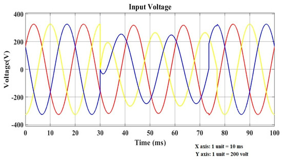
Figure 5.
Input waveform of DVR.
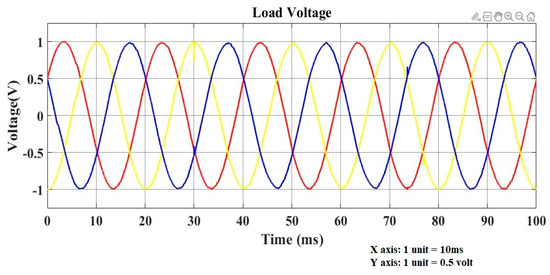
Figure 6.
Output waveform of DVR.
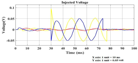
Figure 7.
Injected voltage waveform of DVR.
A DVR is designed for single-phase applications (Figure 8), and it is implemented to compensate for voltage sag issues in the grid system; its hardware parameters are given in Table 3. The setup includes a 48 V transformer, responsible for supplying AC voltage to the grid, and a 12 V transformer, which powers the controller and driver circuit. The DC link capacitor maintains a stable DC voltage, which is then transformed into AC voltage using a single-bridge VSI inverter operated by Space Vector PWM (SVPWM). To maintain power quality, passive filters are employed to eliminate harmonics and unwanted distortions. A 15 V injection transformer delivers the required compensated voltage to restore the grid output during disturbances. The system is tested under voltage sag conditions, where the grid voltage drops to 31 V in the absence of DVR compensation as shown in Figure 9.
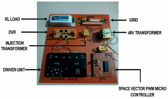
Figure 8.
Hardware model of proposed DVR.
Table 3.
Hardware parameters.
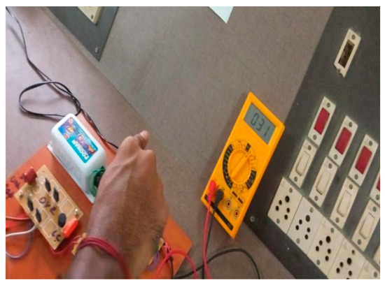
Figure 9.
Voltage at input.
Upon activation, the DVR effectively restores the output voltage to 44 V as shown in Figure 10, ensuring stable operation. For real-time monitoring and validation, measurement tools such as an oscilloscope and multi-meter are utilized to observe the voltage waveforms and overall system performance.
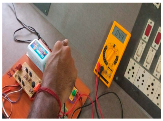
Figure 10.
Voltage at output before using DVR.
A comparative study was performed between conventional DVR and the proposed DVR, and the observations are given in Table 4. By implementing the discussed PWM in the proposed DVR, the THD is reduced by 70% as compared to the original value, whereas conventional PWM reduces only 40% from the original value. This shows that the discussed PWM method is effective when compared to the conventional PWM method.
Table 4.
Comparative study on DVR.
5. Conclusions
This paper presents an enhanced DVR that ensures continuous operation of EV charging stations by effectively mitigating voltage sags and disturbances, thereby safeguarding sensitive equipment and enhancing system reliability. The integration of an SVPWM controller improves the dynamic response and precision of the compensation process, resulting in better voltage regulation and stability. The simulation and real-time implementation results validate the system’s reliability, demonstrating improved efficiency and reduced Total Harmonic Distortion (THD). Additionally, the proposed DVR configuration is scalable and adaptable, making it suitable for future EV charging infrastructure demands while contributing to prolonged equipment lifespan and improved power quality. The real-time work of the proposed DVR is tested with an impedance load of 20Ω and 70 mH, where the implementation of SVPWM control improves voltage regulation and reduces THD by 60–70% compared to conventional PWM methods, which achieve only 40–50% reduction. The proposed model provides a rapid response time (<10 ms), and the efficiency of the proposed DVR is found to be 92%, which is greater than that of conventional designs.
Author Contributions
Conceptualization, T.M.; V.L. and D.R.; methodology, T.M. and K.S.S.; software, K.S.S. and V.T.N.; validation, V.L., K.S.S. and D.R.; investigation, T.M.; D.R. and S.K.E.; writing—original draft preparation, V.L. and K.S.S.; writing—review and editing, supervision, V.L. and K.S.S. All authors have read and agreed to the published version of the manuscript.
Funding
This research received no external funding.
Institutional Review Board Statement
Not applicable.
Informed Consent Statement
Not applicable.
Data Availability Statement
Data are contained within the article.
Conflicts of Interest
The authors declare no conflicts of interest.
References
- Soomro, A.H.; Larik, A.S.; Mahar, M.A.; Sahito, A.A.; Soomro, A.M.; Kaloi, G.S. Dynamic Voltage Restorer—A Comprehensive Review. Energy Rep. 2021, 7, 6786–6805. [Google Scholar] [CrossRef]
- Das, J. Power Quality Issues with Electric Vehicle Charging Stations. In Advanced Technologies in Electric Vehicles; Academic Press: Cambridge, MA, USA, 2024; pp. 187–205. [Google Scholar]
- Farhadi-Kangarlu, M.; Neyshabouri, Y.; Mohammadi, F. Operation of the AC-AC Converter Based Dynamic Voltage Restorer in Weak Distribution Systems. In Proceedings of the 12th Power Electronics, Drive Systems, and Technologies Conference (PEDSTC), Tabriz, Iran, 2–4 February 2021; pp. 1–5. [Google Scholar]
- Essam, A.; Ul-Haq, A.; Iqbal, A.; Jalal, M.; Anjum, A. SRF-Based Versatile Control Technique for DVR to Mitigate Voltage Sag Problem in Distribution System. Ain Shams Eng. J. 2020, 11, 99–108. [Google Scholar]
- Manmadharao, S.; Satputaley, R.J.; Keshri, R.K.; Raghava, B.V.S. Effects of Voltage Sag on Grid-Fed Electric Vehicle Charging Station. In Proceedings of the IEEE 12th Energy Conversion Congress & Exposition—Asia (ECCE-Asia), Singapore, 24–27 May 2021; pp. 1755–1760. [Google Scholar]
- Uthra, R.; Suchitra, D. Fault Ride Through in Grid Integrated Hybrid System Using FACTS Device and Electric Vehicle Charging Station. Energies 2021, 14, 3828. [Google Scholar] [CrossRef]
- Saribulut, L.; Ameen, A. Voltage Sag Detection and Compensation Signal Extraction for Power Quality Mitigation Devices. Energies 2023, 16, 5999. [Google Scholar] [CrossRef]
- ManmadhaRao, S.; Satputaley, R.J.; Keshri, R.K.; Patne, N.R.; Buja, G. Voltage Sag Mitigation Using DVR in Grid-Fed EV Fast Charging Station. In Proceedings of the AEIT International Conference on Electrical and Electronic Technologies for Automotive (AEIT AUTOMOTIVE), Virtual, 17–19 November 2021; pp. 1–6. [Google Scholar]
- Li, Z.; Su, Y.; Guan, T.; Sun, Y.; Hu, K.; Xiang, Z. Improved Strategy for Dynamic Voltage Restorers Considering Voltage Sag Duration. In Proceedings of the Chinese Automation Congress (CAC), Shanghai, China, 6–8 November 2020; pp. 4679–4684. [Google Scholar]
- Chankhamrian, W.; Pinthurat, W.; Marungsri, B. Voltage Dip Mitigation by Series Dynamic Voltage Restorer in Electrical Power System Connected with a Sensitive Resistive Load. In Proceedings of the International Conference on Power, Energyand Innovations (ICPEI), Phrachuap Khirikhan, Thailand, 18–20 October 2023; pp. 70–75. [Google Scholar]


Disclaimer/Publisher’s Note: The statements, opinions and data contained in all publications are solely those of the individual author(s) and contributor(s) and not of MDPI and/or the editor(s). MDPI and/or the editor(s) disclaim responsibility for any injury to people or property resulting from any ideas, methods, instructions or products referred to in the content. |
© 2025 by the authors. Licensee MDPI, Basel, Switzerland. This article is an open access article distributed under the terms and conditions of the Creative Commons Attribution (CC BY) license (https://creativecommons.org/licenses/by/4.0/).