1. Introduction
The efficiency and reliability of power distribution systems are essential for ensuring a stable electricity supply across residential, commercial, and industrial sectors. One of the most critical components of these systems is the distribution transformer, which steps down high-voltage electricity to a usable level for end consumers. However, transformers are prone to failures due to excessive load, aging, overheating, insulation breakdown, and environmental factors, leading to costly disruptions and maintenance challenges [
1]. The voltage reduction procedure is essential for providing safe and useful power to residential and industrial consumers. The distribution transformer is essential for the final voltage adjustment in the electrical distribution network, serving as a fundamental component of the power delivery system. The functionality relies on a complex electromagnetic circuit that must be carefully developed and executed to guarantee efficient operation. To improve the reliability and efficiency of transformers, it is essential to meticulously choose particular auxiliary components and build an exact magnetic circuit, in addition to a sturdy structure and an optimum insulating system [
2].
The operation and maintenance of distribution transformers present some challenges. Overloaded working circumstances and insufficient thermal control are common, resulting in expedited transformer aging and diminished performance. These issues highlight the imperative for data-driven methodologies to monitor and control these devices effectively. Precise and ongoing data gathering can assist in detecting operational inefficiencies and reducing future breakdowns, hence ensuring the durability and dependability of the transformer [
3]. The health and safety of transformers are crucial in electrical distribution systems, as even minor problems can lead to major failures, resulting in extensive equipment damage and negatively affecting the overall stability of the power network. Proactive monitoring and accurate problem diagnosis are essential for minimizing equipment damage and improving network stability [
4,
5]. Traditional transformer monitoring techniques rely on periodic manual inspections, which are inefficient, time-consuming, and unable to provide real-time insights into the operational status of transformers [
6]. To address these limitations, IoT-based smart monitoring systems have emerged as a transformative solution for real-time data acquisition and predictive maintenance [
7]. These systems integrate advanced sensor technologies, wireless communication, and cloud-based analytics to monitor critical transformer parameters, such as voltage, current, temperature, and fault conditions [
8].
Several studies have highlighted the advantages of IoT-driven transformer monitoring systems in enhancing reliability and reducing maintenance costs. Acakpovi et al. proposed a wireless monitoring system using Arduino and XBee modules, which enabled real-time transformer condition tracking and automated fault diagnosis [
9]. Similarly, Zhang et al. introduced an IoT-based monitoring system integrated with ensemble machine-learning techniques to enhance fault detection accuracy [
10]. Also, Srivastava and Tripathi developed a cloud-connected health monitoring framework for distribution transformers, which utilized data analytics to predict failures before they occurred [
11].
Wireless IoT-based monitoring systems are widely used in the business sector to monitor critical performance from remote locations [
12]. These systems enable predictive maintenance, reducing downtime and operational costs while extending the transformer’s lifespan. The processed data can be accessed via mobile applications, providing critical insights into transformer health and operational status [
13]. Furthermore, online measuring devices collect and analyze sensor data over time, ensuring accurate real-time monitoring and fault detection [
14]. Despite these advancements, challenges remain in optimizing transformer monitoring systems for scalability, cost-effectiveness, and integration with smart grid infrastructures [
15]. Recent research suggests that leveraging cloud computing, AI-based predictive models, and remote-control mechanisms can further enhance the performance and responsiveness of transformer monitoring solutions. By incorporating real-time monitoring, fault diagnosis, and predictive maintenance capabilities, IoT-based systems can significantly improve transformer lifespan, minimize downtime, and ensure uninterrupted power supply [
16].
This research introduces an IoT-driven distribution transformer health monitoring system that enhances power grid reliability through real-time monitoring, fault detection, and predictive maintenance. Using ESP32, voltage, current, and temperature sensors, the system continuously tracks transformer health and transmits data to the Blynk app for remote access. This approach reduces reliance on manual inspections, minimizes downtime, and extends the lifespan of the system. The system ensures cost-effective and proactive maintenance by integrating wireless monitoring, automated fault detection, and cloud-based analytics, optimizing power distribution efficiency. The proposed solution contributes to sustainable energy management and the development of intelligent power grids.
2. Proposed Methodology
The proposed system is a comprehensive design methodology that aims to create a strong and efficient system for monitoring critical parameters of distribution transformers.
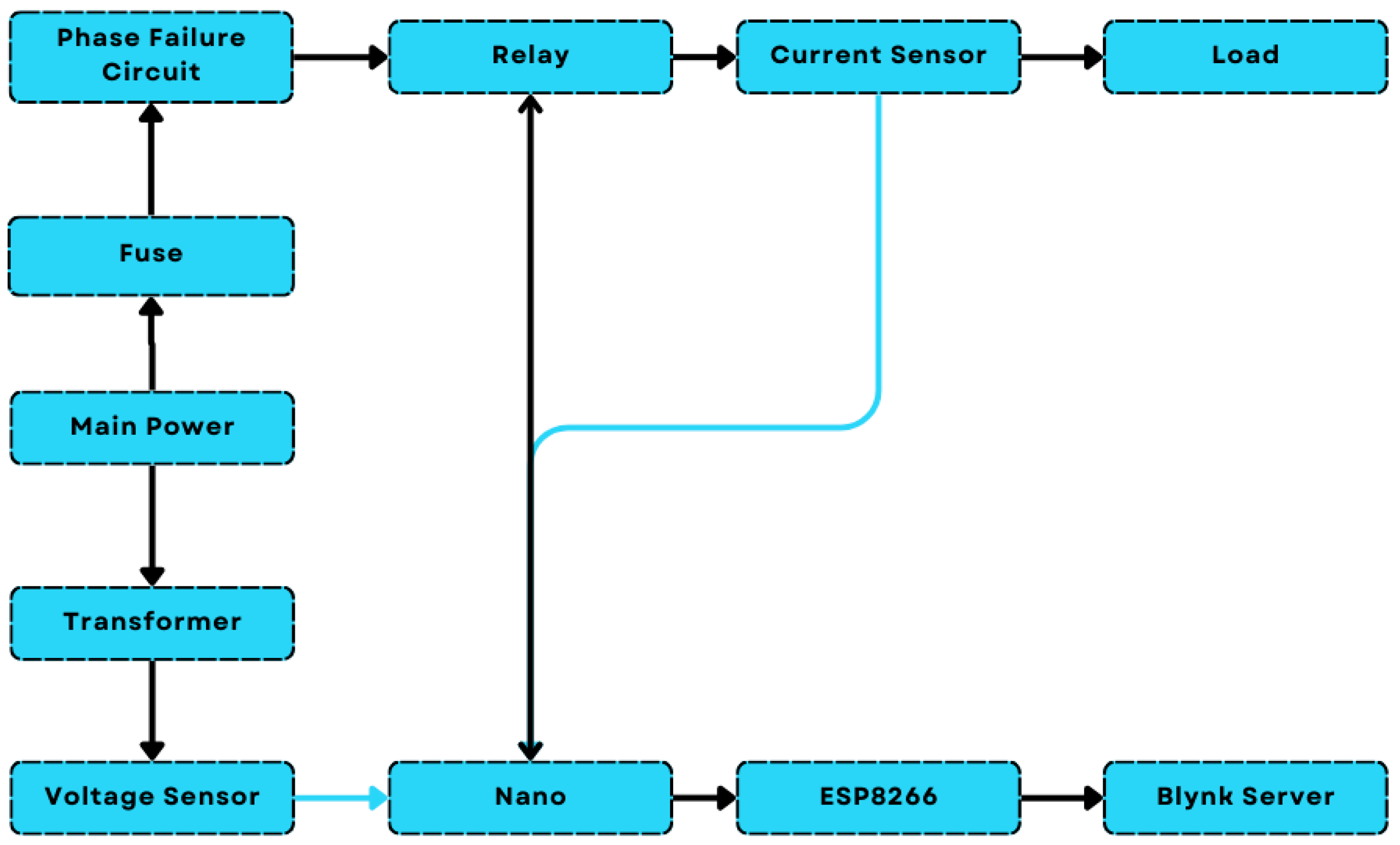
Figure 1 shows the block diagram of the proposed system; the proposed system consists of a complex network of components that monitor distribution transformers. The system includes voltage sensors, current sensors, temperature sensors, a relay system, and a 2A fuse. The design phase focuses on integrating these components for fault detection and protection. The connectivity and visualization phase uses the Blynk platform for real-time data access. The validation phase ensures the system aligns with objectives and robust fault detection mechanisms. The implementation phase brings the system to life, integrating sensors, relay systems, and Blynk connectivity for optimal performance and health. The system also allows for remote monitoring via the Blynk platform, enhancing reliability and efficiency. The symbiotic network ensures seamless data flow, protective measures activation, and enriched data transmission for remote monitoring. This sophisticated and reliable system is ideal for effective distribution transformer condition monitoring in power distribution systems.
The circuit diagram of the proposed system is shown in
Figure 2; it includes voltage sensors (ZMPT101B) to measure electrical characteristics, current sensors (ACS712) to track current flow, and a temperature sensor (DS18B20) to monitor body and oil temperatures. A relay system (BC547 transistor and 5 V relay) provides fault protection, including overvoltage, overcurrent, phase failure, and earth faults, while a 2A fuse ensures circuit safety by breaking during excessive current. The microcontroller (ESP32) connects to the Blynk platform for real-time data visualization and remote monitoring. This system enables seamless data flow, fault detection, and efficient transformer condition monitoring.
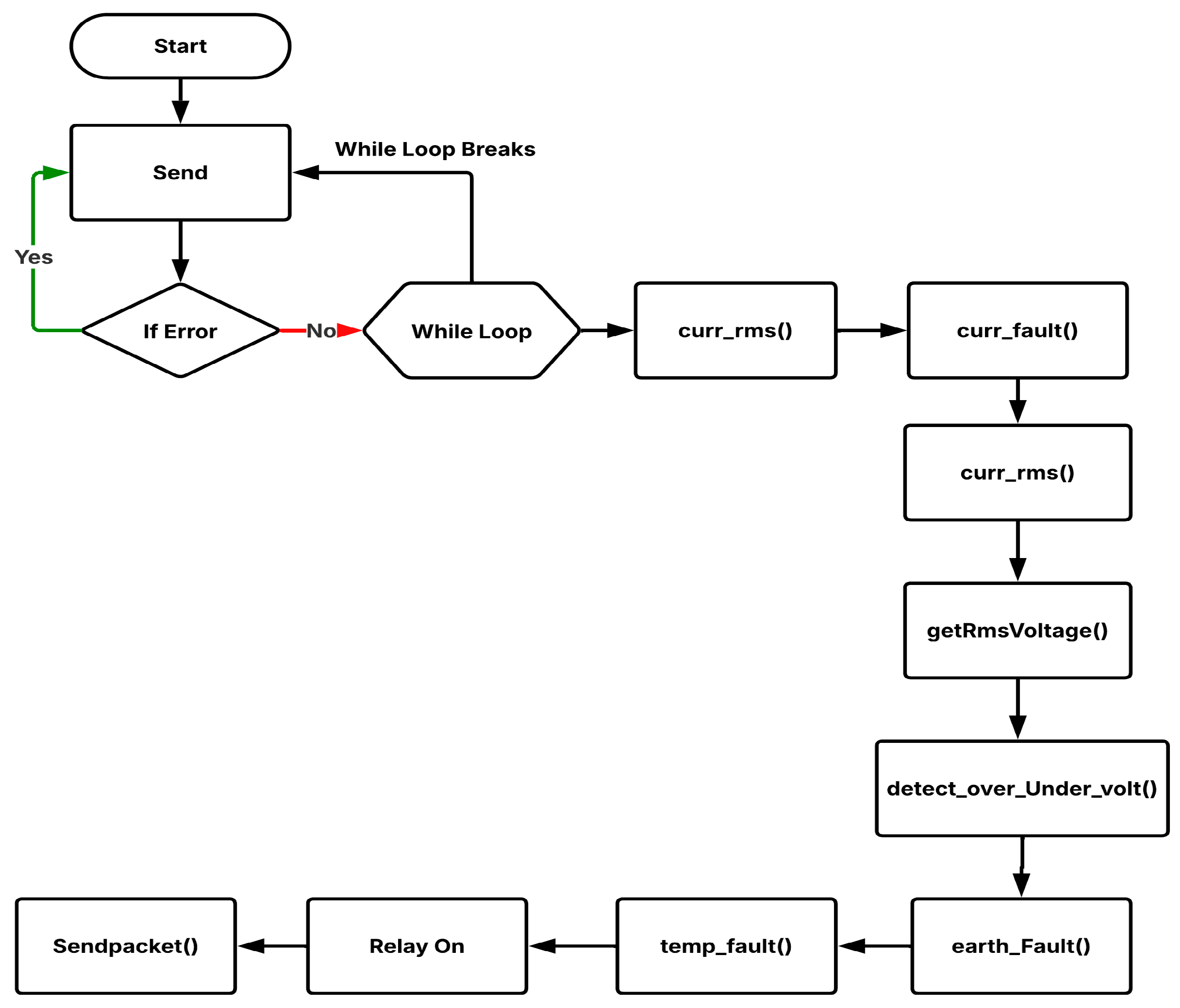
Figure 3 is a flowchart that outlines the operation of an IoT-driven health monitoring system for a smart power grid distribution transformer. It starts with a “Start” node, leading to the “Send” operation for data transmission. A decision step, “IF Error”, checks for errors. If an error occurs, the system loops back to resend data; otherwise, it enters a “While Loop” for continuous monitoring until a condition is met. Within the loop, functions assess the transformer’s health, curr_rms() calculates current RMS, curr_fault() detects current faults, getRmsVoltage() retrieves voltage RMS, detect_over_under_volt() evaluates voltage anomalies, earth_fault() checks for ground faults, and temp_fault() identifies temperature issues. If the parameters are satisfactory, the relay activates, ensuring proper operation. Finally, the sendpacket() function transmits data for analysis. This process ensures real-time monitoring, fault detection, and predictive maintenance for smart grids. The proposed system can be scaled for large-scale power distribution networks by employing multiple IoT nodes with centralized cloud storage for data processing. However, challenges such as network latency, data security, and integration with legacy infrastructure must be addressed. Future work will focus on optimizing communication protocols and implementing AI-driven predictive maintenance for improved scalability.
3. Results and Discussion
Figure 4 shows a prototype of an IoT-based transformer health monitoring system for smart grids. The system features components on a wooden board that tracks voltage, current, and temperature. A microcontroller gathers sensor data and sends it to a remote platform via IoT.
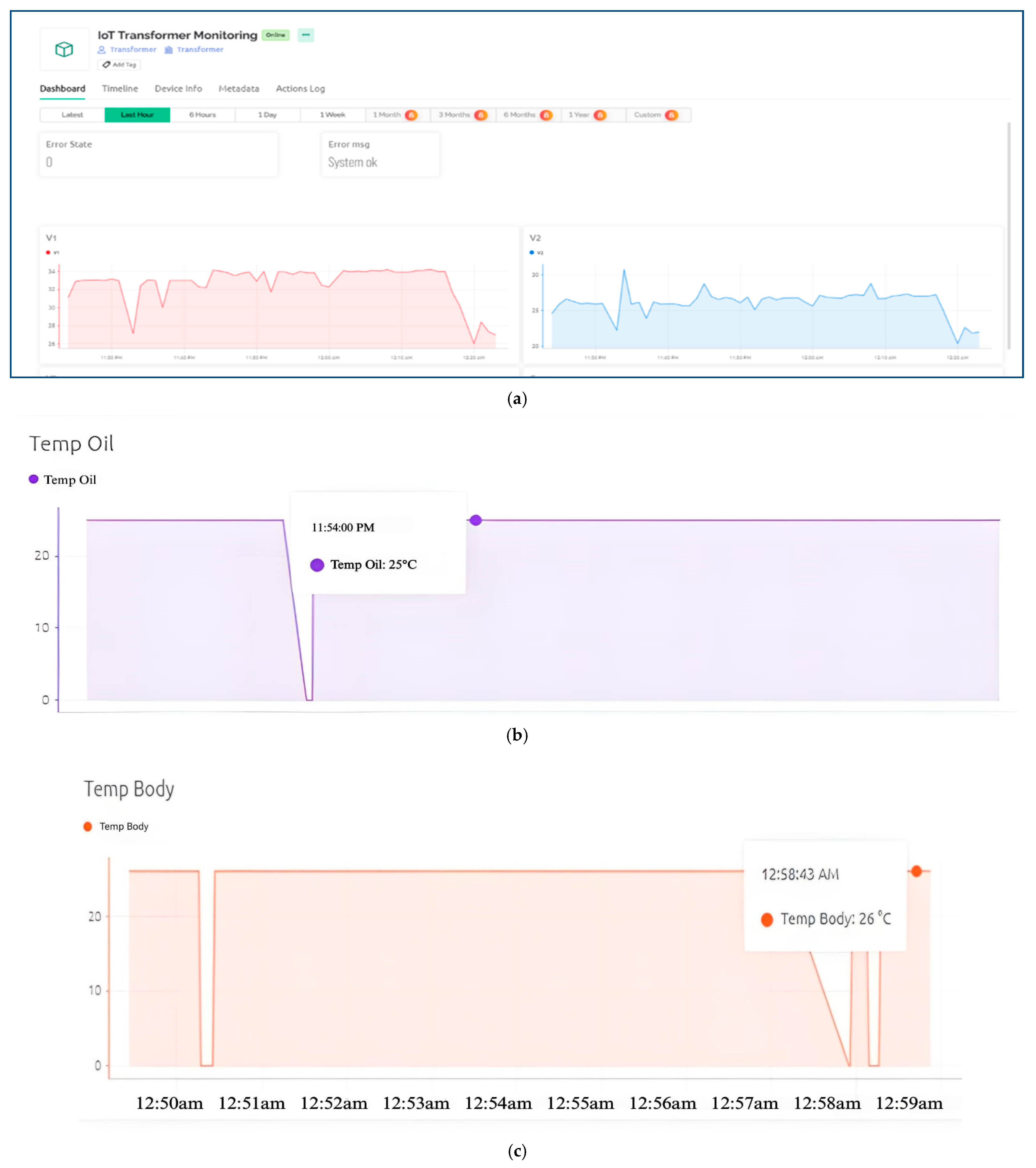
Figure 5 shows the system that monitors key electrical parameters via an online dashboard.
Figure 5a shows real-time graphs of voltage (V1, V2) and current, with V1 (red) and V2 (blue) indicating stable operation. The status reads “Error State: 0” and “Error Message: System OK”, confirming no faults.
Figure 5b monitors the transformer oil temperature, which remains stable at 25 °C, indicating optimal performance without overheating.
Figure 5c shows transformer body temperature data under normal operating conditions. The temperature remains stable at around 26 °C, with slight fluctuations due to transient disturbances, sensor inaccuracies, or loading variations. Despite these deviations, the overall temperature profile remains consistent, indicating the transformer operates within safe thermal limits. The recorded temperature at 12:58:43 A.M. is 26 °C, confirming the system’s effective monitoring capability.
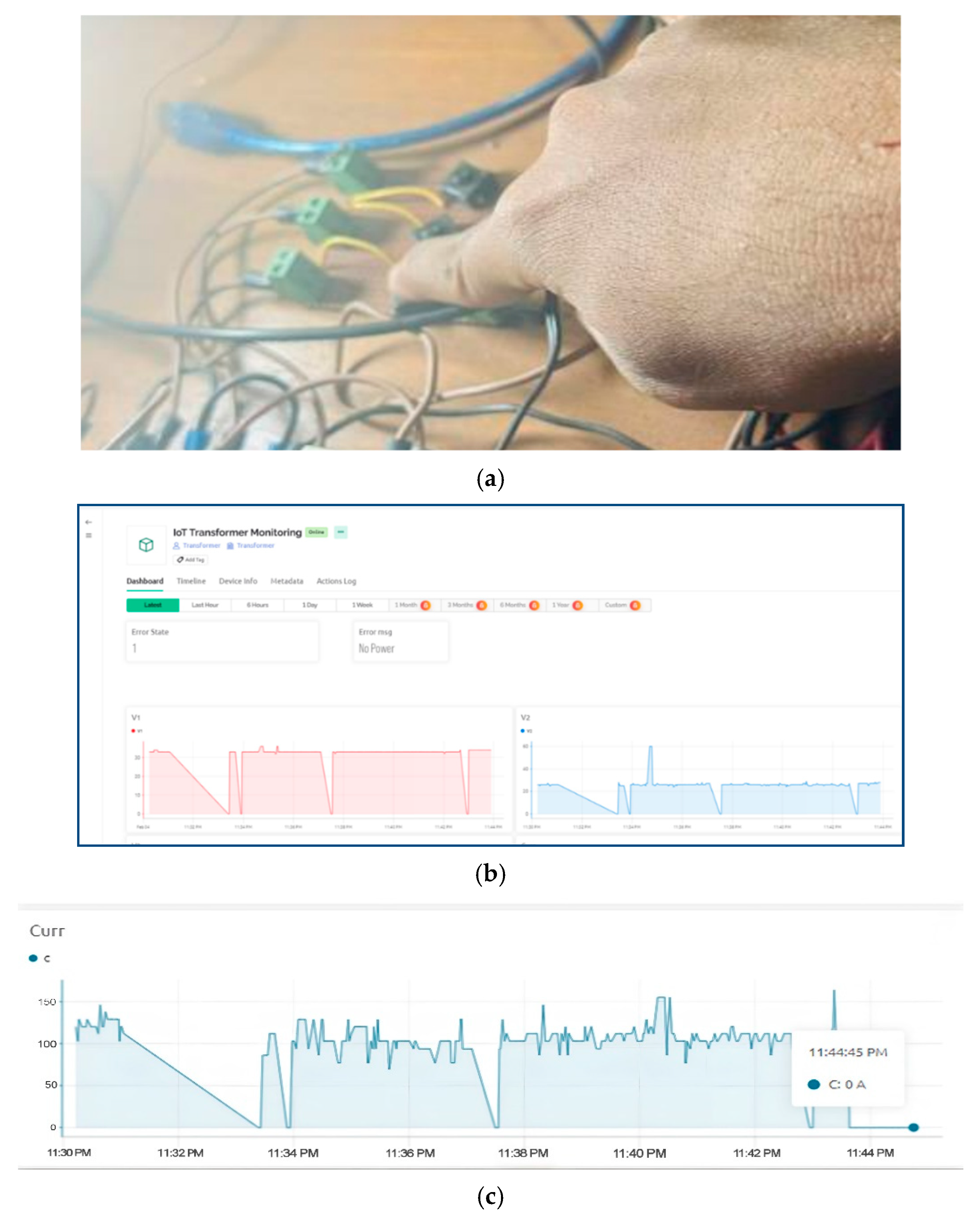
Figure 6 illustrates an initial failure. The image captures a physical inspection of the transformer setup, and
Figure 6a shows a manual assessment of the connections and components.
Figure 6b shows the system output during a failure and provides diagnostic insights via the dashboard, showing an “Error State” with the message “No Power”, indicating a power failure. Graphs display voltage (V1) fluctuations and drops, along with current (V2) variations, highlighting the impact on power transmission. These anomalies confirm the system’s effectiveness in fault detection and alerting, emphasizing the importance of real-time monitoring for proactive maintenance in smart grids.
The graph in
Figure 6c shows the transformer’s behavior after a phase failure. A current drop indicates the failure, followed by fluctuations from transients and reconnection attempts. The current then drops to zero, activating protective mechanisms. This highlights the IoT system’s effectiveness in detecting and recording phase failures, providing real-time insights, alerts, and interventions for reliability and safety.
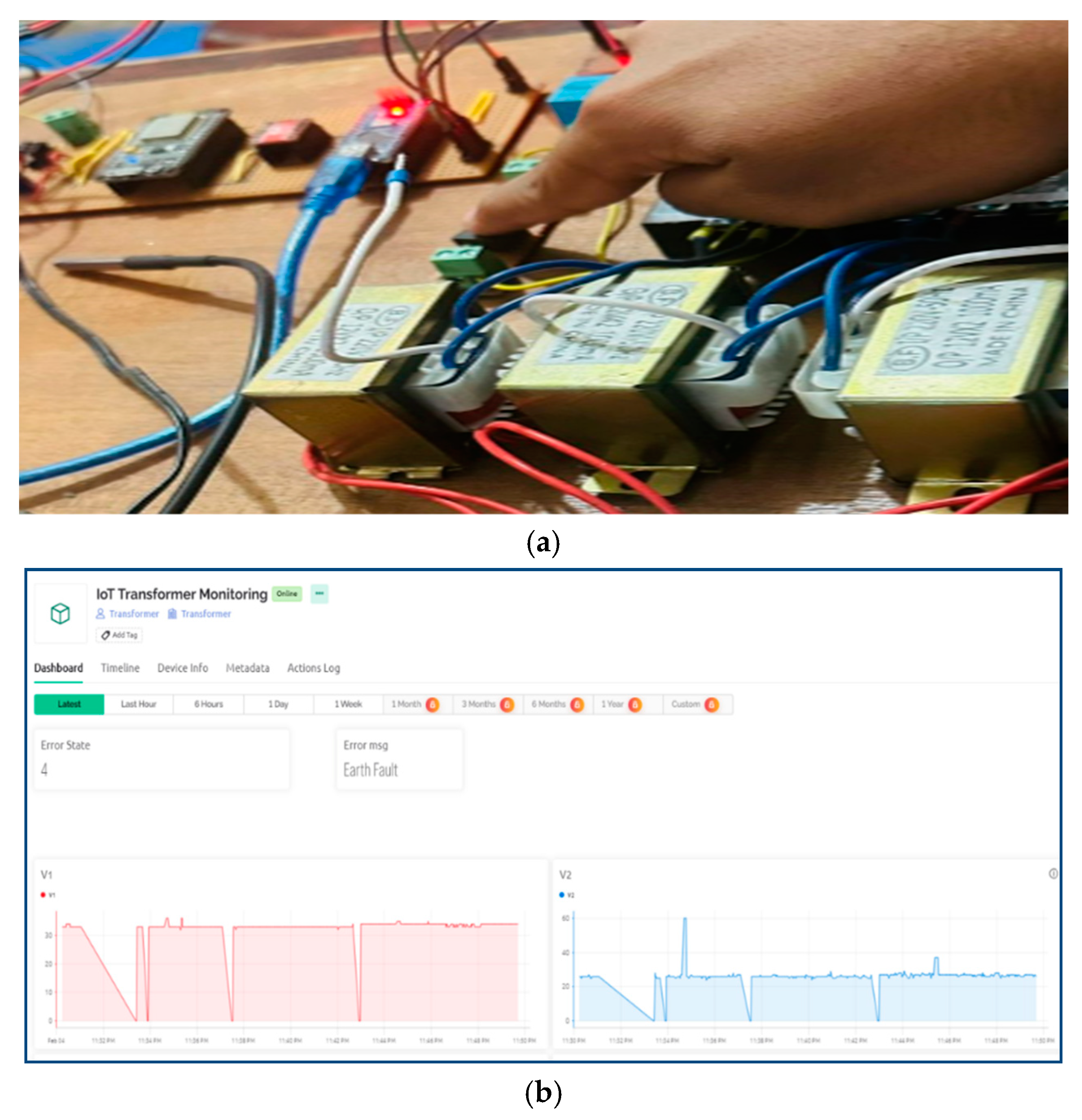
Figure 7 demonstrates the system’s response to an earth fault.
Figure 7a depicts the hardware setup initializing an earth fault, which is intentionally created to test the monitoring system’s capability to detect and respond to this anomaly.
The IoT system detects faults and alerts operators in real time. In
Figure 7b, the dashboard shows an “Earth Fault” message. Voltage graphs (V1 and V2) reveal a sharp drop and fluctuations, indicating the fault and the system’s response. This reflects the system’s ability to manage or isolate issues effectively.
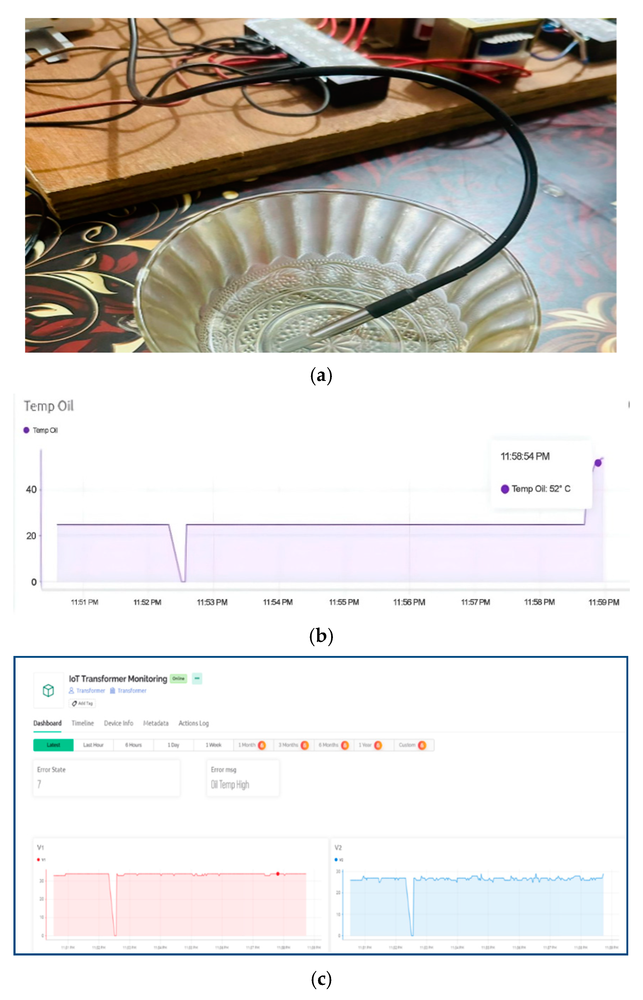
Figure 8 demonstrates the system’s response to high transformer oil temperature. Initially stable,
Figure 8b shows that the temperature rises to 52 °C, exceeding the threshold and triggering an “Oil Temp High” error message on the dashboard.
Figure 8c Voltage graphs (V1 and V2) show initial fluctuations due to protective mechanisms, with V2 stabilizing after the fault is managed. These results confirm the IoT system’s effectiveness in monitoring, detecting, and alerting operators to overheating, ensuring timely intervention and enhanced transformer reliability and safety.
Table 1 highlights the system’s performance throughout several error states, dependent upon critical transformer characteristics. In the normal condition (Error State 0), the voltage is within the acceptable range, the oil temperature is 25 °C, the body temperature is 26 °C, and the current is stable, signifying optimal functionality.
In Error State 1, a “No Power” notification is recorded. Voltage declines, oil, and body temperatures vary, and the current becomes erratic, indicating power failure or disconnection. In Error State 4, designated “Earth Fault”, the voltage undergoes a partial decline while the oil temperature ascends to 52 °C. The body temperature remains constant, but the current exhibits fluctuations due to the malfunction. Error State 7, designated as “Oil Temp High”, indicates stable voltage; however, the oil temperature reaches a maximum of 52 °C, while the body temperature remains constant and the current is unaffected, suggesting overheating without further electrical irregularities.
Table 2 presents a cost analysis of the proposed system, detailing components, quantities, and their pricing in TK. The primary components consist of a single-phase 24 V transformer (3 units at 735 TK), an Arduino Nano (1 unit at 700 TK), an ESP32 microcontroller (1 unit at 550 TK), AC voltage meters (3 units at 1080 TK), and current sensors (3 units at 835 TK). Supplementary components, including relays, a temperature sensor, and a buck converter, augment the overall expense. The system is constructed at a total cost of 9250 TK, providing an economical and efficient option for transformer monitoring. Future work will involve deploying the system in real-world distribution transformers for an extended period. This will allow continuous data collection, fault occurrence tracking, and system adaptation to varying operational conditions, ensuring improved reliability and effectiveness.


 ,
, 


