Proceeding Paper

On the Electrical Resistivity Measurement Methods and Properties of Conductive 3D-Printing PLA Filaments †

by
César M. A. Vasques
1,2,*,
João P. R. Ferreira
1,
Fernando A. V. Figueiredo
1,3,4 and
João C. C. Abrantes
1
1
proMetheus, Escola Superior de Tecnologia e Gestão, Instituto Politécnico de Viana do Castelo (IPVC), 4900-347 Viana do Castelo, Portugal
2
Centro de Tecnologia Mecânica e Automação (TEMA), Departamento de Engenharia Mecânica, Universidade de Aveiro, 3810-193 Aveiro, Portugal
3
Smile.Tech—Robótica, 4400-055 Vila Nova de Gaia, Portugal
4
Instituto Superior de Entre o Douro e Vouga (ISVOUGA), 4520-181 Santa Maria da Feira, Portugal
*
Author to whom correspondence should be addressed.
Presented at the 5th International Electronic Conference on Applied Sciences, 4–6 December 2024; Available online: https://sciforum.net/event/ASEC2024.
Eng. Proc. 2025, 87(1), 26; https://doi.org/10.3390/engproc2025087026
Published: 25 March 2025
(This article belongs to the Proceedings of The 5th International Electronic Conference on Applied Sciences)

Abstract

:
In recent years, there has been a growing interest in and research efforts enabling the use of composite conductive 3D-printing filaments in material extrusion additive manufacturing processes, which can bestow novel and distinctive functions onto 3D-printed components. These composite filaments, in general blending a thermoplastic with carbon-based materials, open up new research and development avenues in electronics and sensors. Additionally, by exploring the underlying piezoresistivity of conductive filaments, they also enable the creation of novel structural components possessing integrated (intrinsic) self-sensing capabilities that can be effectively employed in structural health monitoring of critical components. However, piezoresistivity features require measuring the electrical resistance of structures made with these conductive filaments, which might be hard, especially when measuring small changes in resistance caused by mechanical loads on the component. The goal of this study is to compare the two- and four-probe methods for measuring the electrical resistance of 3D-printed parts and to look at how different types of electrical contacts and bonding may affect electrical resistivity measurement and self-sensing capabilities. The research is conducted on 3D-printed specimens using a conductive composite PLA (polylactic acid) filament from Protopasta. The efficiency of each method and the influence of the bonding and electrodes on the measurements are experimentally analyzed and discussed. Our experiments reveal that the four-probe method consistently yields resistivity values between 15.35 and 16.38 Ω · cm, while the two-probe method produces significantly higher values (up to 52.92–62.37 Ω · cm), underscoring the impact of wire and contact resistances on measurement accuracy.

1. Introduction

Additive manufacturing has experienced significant advancements in recent years, driven by innovations in 3D-printing technologies. Among these advancements, conductive 3D-printing filaments have emerged as a promising area of research, enabling novel applications in electronics, sensors, and structural health monitoring. In 2012, Leigh et al. [1] developed an early conductive PLA (polylactic acid) filament for sensory components, laying the groundwork for subsequent innovations. Later in 2016, Jo et al. [2] demonstrated the potential of thermoplastic composites with carbon black, paving the way for low-cost and efficient 3D-printed electronic devices. These developments have opened new opportunities to manufacture complex, custom-tailored conductive parts with embedded sensing capabilities [3,4,5,6,7,8,9].
One critical property of conductive filaments is piezoresistivity, which enables them to exhibit changes in electrical resistance under mechanical stress [10,11]. This property significantly enhances their functionality, making them suitable for applications such as strain and damage sensing. In this context, resistivity—a fundamental electrical property—plays a key role in the performance and application of these materials. Studies in [12,13,14] have shown how factors like layer height, raster patterns, and printing parameters influence resistivity anisotropy and self-sensing performance. Accurate resistivity measurements are essential for optimizing filament selection, manufacturing processes, and 3D-printed part design. However, challenges remain in achieving precise measurements due to issues like contact resistance and the limitations of conventional methods.
Chung [15] emphasized that resistance measurements should ideally reflect the material’s intrinsic resistance, excluding contributions from contact resistance at the electrode interface. Watschke et al. [16] explored bonding techniques, such as silver paste and inlaid wiring, to reduce contact resistance and improve measurement precision. These findings highlight the importance of combining accurate methodologies with well-designed electrodes to ensure reliable resistivity measurements. The two-probe method, though widely used, is susceptible to errors due to wire and contact resistances [15,17]. In contrast, the four-probe method has gained prominence for its precision in eliminating extraneous resistances from wires and contacts [18,19]. This method is particularly critical for characterizing conductive 3D-printed PLA filaments, which are increasingly used in self-sensing applications. The four-probe method has been widely employed to evaluate the effects of parameters such as layer height, nozzle temperature, and printing velocity on resistivity. Dul et al. [13] characterized a composite ABS/carbon nanotube filament using the four-probe method, while Kwok et al. [3] used the two-probe method to calculate filament resistance. Watschke et al. [16] further investigated bonding techniques, finding that silver paste was highly effective in reducing contact resistance.
Extensive research has been also conducted to advance conductive filaments [20]. For instance, Zhang et al. [12] demonstrated that parameters like raster width, air gap, and layer thickness directly affect the resistivity of 3D-printed composites, with printed parts exhibiting higher resistance than the raw filament. Hampel et al. [21] analyzed conductive filaments based on ABS (acrylonitrile butadiene styrene) and PLA, reporting poor reproducibility for ABS but effective use of ProtoPasta PLA in developing a flashing LED (light-emitting diode) circuit board. A systematic evaluation of the resistivity of 14 commercially available filaments as unprocessed filament feedstock, extruded fibers, and 3D-printed extruded structures was performed in [22]. Reviews in [4,5] provide comprehensive insights into manufacturers, resistivity, and applications of conductive filaments.
In light of these findings, this study aims to compare the two-probe and four-probe methods for measuring the electrical resistance of 3D-printed parts, focusing on how testing methods and electrode designs influence results. Specimens fabricated using a conductive PLA filament from ProtoPasta [23] were used to evaluate the methods’ effectiveness and the impact of electrode types and electrical connections on resistivity measurements. The study also demonstrates the adaptability of the four-probe method, showcasing its ability to minimize contact resistance effects and provide accurate measurements. By advancing the understanding of resistivity and piezoresistivity measurements, this study highlights the potential of conductive 3D-printed PLA materials in structural health monitoring and other self-sensing applications.
Despite several studies addressing the electrical properties of conductive filaments [1,2,3,4,5,6,7,8,9], a systematic comparison between the two-probe and four-probe methods—especially considering the effect of different electrical bonding techniques on contact resistance—has not been reported. This study bridges that gap by providing a detailed experimental comparison and by quantifying the influence of bonding resistance on the intrinsic resistivity measurements.

2. Materials and Methods

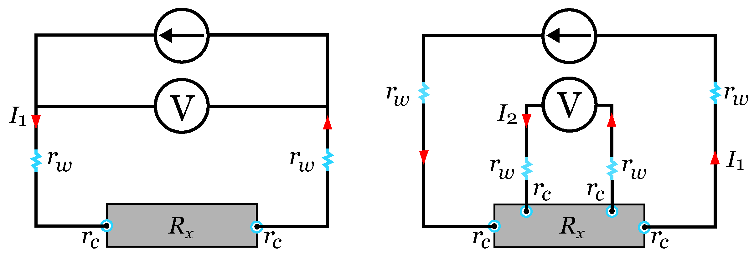
2.1. Electrical Resistivity Measurement Methods and Techniques

The two-probe method measures a resistance by applying a current across the material and measuring the resulting voltage; while the four-probe method provides a more accurate measurement of the material by using two additional probes to separate the current-carrying and voltage-sensing paths, minimizing extrinsic resistance effects. As such, in contrast to the two-probe method, the four-probe method measurement is not affected by the resistance of the wires and contacts associated with the electrodes. Figure 1 illustrates the electrical schematics of these two methods.
With the two-probe method, the electrical resistance is measured with two electrodes. Each electrode is positioned at one end of the intrinsic resistance being measured, R x . A constant current, I 1 , is supplied through a device, and the resulting voltage, V, is measured by the same device. A constant current, I = I 1 , is prescribed into a known value and the total measured resistance is R = 2 r w + 2 r c + R x , yielding from Ohm’s first law, V = R I , the measured voltage and resistance as
V = I 1 ( 2 r w + 2 r c + R x ) R x = V I 1 ( 2 r w + 2 r c ) .
In this case, the extrinsic resistance effects of the wires, r w , and contacts, r c , which are more difficult to measure and quite often unknown, will always be present in the measured voltage, consequently affecting the measurement error as the intrinsic resistance to be measured becomes smaller or the extrinsic resistances effects become more relevant.
With the four-probe method, four electrodes are used, commonly referred to as current electrodes and potentiometric (voltage) electrodes. The measurement of the voltage drop and the current source are handled by separate devices. If the current source provides a constant current I 1 and the total current I = I 1 + I 2 flows across the intrinsic resistance R x to be measured, according to Ohm’s first law we have
V = 2 I 2 ( r w + r c ) + ( I 1 + I 2 ) R x R x = V I 1 ( for I 2 0 ) .
The voltmeter has a high impedance, inducing an extremely low current I 2 for voltage measurement. Therefore, considering I 2 0 and relatively low extrinsic resistances, the parasitic resistance effects from external wires and contacts are largely mitigated, effectively eliminating their influence on the measurement equation.

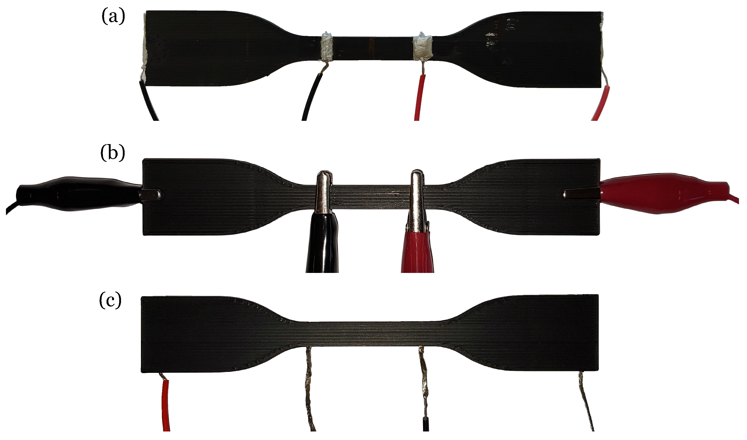
2.2. 3D-Printed Self-Sensing Material Specimens

ISO/ASTM standards classify additive manufacturing technologies into seven types based on layer creation, energy source, and fuse material. Material extrusion, one of these seven additive manufacturing methods, builds 3D parts from thermoplastic or composite filaments, where continuous thermoplastic filament is fed through a heated nozzle and deposited layer by layer onto the build platform. Material extrusion was initially developed and patented as fused deposition modeling (FDM), currently trademarked by Stratasys (Rehovot, Israel). Fused filament fabrication (FFF) is another alternative designation that falls under this category developed by the members of the RepRap project. Material extrusion uses a variety of materials, but thermoplastics like ABS, PA (Nylon), HIPS, PLA, and TPU are the most popular. Extrusion can be used with composite materials if enough base thermoplastic material is present to ensure fusion between layers. This implies that printed components can contain wood, metal, or carbon fiber, with increased functionality.
The electrically conductive material specimens considered in this work were 3D printed with an Ender-3 v2 extrusion material printer from Creality and a 1.75 mm diameter electrically conductive composite PLA filament from Protopasta [23]. Due to the inherent piezoresistive properties exhibited by these materials that make them suitable for applications involving structural health monitoring of critical engineering components, we have designated them as “self-sensing”. The adopted printing parameters were as follows: layer height 0.2 mm, infill density 100%, printing temperature of 210 °C, built plate temperature 60 °C, and line width 0.4 mm.
Slicing, defining the path and parameters of the printer head, and G-code generation were performed with Ultimaker Cura 5.7.2. The path was enforced such that the material deposition lines formed an infill pattern that results in a unidirectional material structure. The deposition lines of the extruded material are longitudinal to the specimen and parallel to the direction of the imposed electric current applied to the material. The dimensions and geometric shape of the material specimens were defined according to the tensile testing standard ASTM D638 [24], choosing the type IV model. The geometry of the specimens is suitable for the execution of the mechanical tensile tests on plastics, to be subsequently used for the characterization of the material’s piezoresistivity. Additionally, the dimensions and geometry were selected so as to not disrupt the electrodes or the electrical measurements.
As shown in Figure 2, the specimens were equipped with four electrodes. For the measurement of electrical resistance using the two-probe method, only the central electrodes E 3 and E 4 are used. The central part of the specimen has a constant cross-section with a width l 2 and height l 3 . The electrodes are separated along the length by a distance l e . For the four-probe method, the electrodes E 1 and E 2 are considered. In this method, E 1 and E 2 , known as the current electrodes, apply the current, while the voltage drop is measured using the electrodes E 3 and E 4 .
The implemented electrical connections consist of conductive wires, where one end of the wire is carefully stripped and subsequently interconnected with the specimens. This allows for the implementation of various electrical bonding techniques. As we can see in Figure 3, three techniques were implemented. In technique (a), a layer of silver-conductive paint (RS Pro Silver Conductive Paint 123-9911) is applied to the areas of the specimen where the wires will be connected. The wire is then glued to the painted surface using a silver-conductive epoxy adhesive (MG Chemicals 8330-19G). Technique (b) involves the use of common crocodile clips to establish the connection, as frequently employed in laboratories. Lastly, using the third technique in (c), the wires were fixed into the specimen during the printing process (inlaid during printing). Part of the printing was executed over the wires, securing them to the inside of the specimen.
During the assembly of the electrodes, it is challenging to control the positioning of the wires. As a result, for each case, the distance between electrodes l e presents different values. The measurement of l e is subsequently carried out using a good resolution caliper, ensuring the consistent acquisition of the smallest distance between the contacts. Table 1 displays the distance l e for each case and the dimensions of the central section of the specimens. These data will be necessary for calculation of the resistivity.

2.3. Instrumentation and Experimental Apparatus

The experimental setup depicted in Figure 4 illustrates the apparatus employed to conduct a comparative analysis and investigation of the accuracy of both two- and four-probe methods and the influence of the type of electrode electrical bonding on the measurements. The electrical resistance of the specimens was measured with a Keysight 34460A multimeter using both the two- and four-probe options available by the equipment according to the manufacturer’s instructions [25]. For the electrical connections, common electrical parts like crocodile clips, contact plugs, and coaxial BNC socket to terminal block adaptors were used with UL-standard cables having a stranded tinned copper conductor (RS UL1007 300V Hook-up Wire) with a cross-sectional area of 0.08 mm2 and PVC insulation. In addition, an experimental in-house methodology was developed for the four-probe measurement. In this regard, a USB 6002 low-cost, multifunction DAQ device with eight analog inputs (16-bit, 50 kS/s) from National Instruments was used and connected to a computer through a USB connection. All analog signals were synchronously acquired with a 16-bit resolution and a sampling frequency of at least 1 kHz.
Regarding the current source for the developed in-house methodology, a constant current I was applied to the external electrodes, E 1 and E 2 , using a E36312A power supply from Keysight. With the USB 6002 data acquisition system, the voltage drop between the central electrodes was measured, and the electrical resistance of the 3D-printed specimen between the internal contacts E 3 and E 4 was determined using Equation (2).
Upon conducting the calculations for electrical resistance using both a multimeter and a data acquisition system, it becomes possible to subsequently determine the material resistivity through Ohm’s second law
ρ = R x A l e ,
where ρ is the filament material resistivity, l e is the length between the internal electrodes E 3 and E 4 , and A is the constant cross-sectional area of the specimen in the inner region between the internal electrodes.

3. Results and Discussion

3.1. Research Rationale and Test Plan

Three specimens were used for the measurements, each with a different electrical connection (electrical bonding variant): specimen (a) with silver paint plus silver paste; specimen (b) with crocodile clips; and specimen (c) with inlaid connections during printing. The measurements were performed at a constant temperature of 25 °C, and the results were collected only after two minutes to allow the measurement devices to stabilize after the electrical connections with the specimens. First, the resistance of each specimen was measured using the four-probe method with the Keysight 34460A multimeter. Then, the resistance was measured again using the same multimeter, but this time with the two-probe method. The results of these measurements are presented in Table 2. Further measurements were conducted using the USB 6002 data acquisition system with the four-probe method. These measurements were performed for each specimen at different current values of 5 mA, 10 mA, 15 mA, and 20 mA. The results are shown in Table 3. The average values from Table 3 are also presented in Table 2 for comparison.

3.2. Electrical Resistivity Measurement Results

The results presented in Table 3 reveal that the four-probe method remains unaffected by wire and electrical contact resistance. The consistent values obtained across various electrical bonding variations support this conclusion. Notably, when currents of 15.04 mA and 19.97 mA are applied, there is a clear upward trend in the resistivity values. These outcomes align with previous research conducted by Watschke et al. [16], which demonstrated that resistance in their specimens tends to increase when currents exceed approximately 10 mA. Thus, it is evident that specific current values play a significant role in the electrical resistance of the material.
Based on Table 2, it is evident that the resistivity obtained using the two-probe measurement method is higher compared to the four-probe method. This difference can be attributed to the resistance of the wires and contacts used and, therefore, the resistance of the bonding area. As expected, even with the multimeter, the four-probe method is not affected by the resistance of the wires and electrical contacts, having similar values to the four-probe method performed using the data acquisition system.
Additionally, it can be observed that the contact surfaces with the lowest resistances and, thus, preferred for measurements, are those composed of silver paint plus silver paste. This observation is supported by the smaller difference in resistance obtained between the four-probe and two-probe measurements with the multimeter. The Table 4 presents the resistance values of the wires and contacts.
The resistivity values of the printing material obtained in this experiment can be compared to those provided by the manufacturer and those obtained from other experimental studies. Discrepancies in values may arise due to variations in printing parameters. Therefore, these values can serve as references but not as definitive target values. The manufacturer specifies that the resistivity of the resin used for filament fabrication is 15 Ω · cm, and the resistivity along the xy layers is 30 Ω · cm [23]. Ahr et al. [26] obtained resistance values of 21 Ω · cm for specimens produced using the same filament and similar printing parameters. In the study conducted by Watschke [16], for specimens fabricated using the same filament and similar printing parameters, the obtained resistivity value was 6 Ω · cm. Our study emphasizes that such discrepancies underscore the importance of selecting an appropriate measurement technique for accurate resistivity characterization. It is important to note that the electrical bonding area, in the case of silver paste and silver paint, can vary depending on the user’s application. Similarly, in the case of inlaid connections made during printing, they can be made with wires of different sizes, and, over time, the crocodile clips tend to penetrate the material. These factors will directly impact the electrical bonding resistance.
Our findings not only confirm that the four-probe method significantly reduces measurement errors associated with wire and contact resistances but also quantitatively demonstrate the impact of different bonding techniques, thereby advancing the current understanding of measurement accuracy beyond what has been reported in prior studies.

4. Conclusions

The results obtained with both the multimeter and the DAQ system demonstrate that the four-probe method is both reliable and practical for accurately measuring the electrical resistivity of conductive 3D-printing filaments. Our findings confirm that the influence of wire and contact resistances is significantly reduced when using the four-probe method compared to the conventional two-probe technique. Quantitatively, the four-probe method yielded resistivity values between 15.36 and 16.38 Ω · cm, whereas the two-probe method produced values as high as 52.92–62.37 Ω · cm. These results confirm that the four-probe technique effectively minimizes errors associated with extraneous resistances, providing a more accurate assessment of the material’s intrinsic resistivity. This improvement in measurement accuracy validates the superiority of the four-probe approach and underscores its importance for future studies involving conductive materials and self-sensing applications.

Author Contributions

Conceptualization, C.M.A.V.; methodology, C.M.A.V., F.A.V.F. and J.C.C.A.; software, J.P.R.F. and F.A.V.F.; validation, C.M.A.V. and J.P.R.F.; formal analysis, C.M.A.V. and J.P.R.F.; investigation, all; resources, C.M.A.V. and J.C.C.A.; data curation, J.P.R.F.; writing—original draft preparation, C.M.A.V. and J.P.R.F.; writing—review and editing, C.M.A.V.; funding acquisition, C.M.A.V. and J.C.C.A. All authors have read and agreed to the published version of the manuscript.

Funding

The authors gratefully acknowledge the funding provided by the Foundation for Science and Technology (FCT) of Portugal, within the scope of the project of the Research Unit on Materials, Energy and Environment for Sustainability (proMetheus, https://tech.ipvc.pt/unidades.php?u=PROMETHEUS, 1 January 2025), Ref. UID/05975/2020, financed by national funds through the FCT/MCTES; and the funding provided within the scope of the “Agenda DRIVOLUTION: Transition to the Factory of the Future”, project no. C632394276-0046698 with operation code 02/C05-i01.02/2022.PC644913740-00000022, within the framework of the Agendas/Mobilizing Alliances for Reindustrialization, Notice no. 2022-C05i0101-02, project 23, of the Recovery and Resilience Plan (PRR) of Portugal.

Data Availability Statement

Not applicable.

Conflicts of Interest

The authors declare no conflict of interest.

References

  1. Leigh, S.J.; Bradley, R.J.; Purssell, C.P.; Billson, D.R.; Hutchins, D.A. A simple, low-cost conductive composite material for 3D printing of electronic sensors. PLoS ONE 2012, 7, e49365. [Google Scholar] [CrossRef]
  2. Jo, A.; Chae, H.; Kim, Y.; Kim, H.; Paek, S.; Soum, V.; Jang, W.; Ryu, S.R.; Kwon, O.S.; Shin, K. Formulation of conductive filament composited of thermoplastic with carbon black for a simple 3D printing electrical device. J. Nanosci. Nanotechnol. 2016, 16, 8415–8418. [Google Scholar] [CrossRef]
  3. Kwok, S.W.; Goh, K.H.H.; Tan, Z.D.; Tan, S.T.M.; Tjiu, W.W.; Soh, J.Y.; Ng, Z.J.G.; Chan, Y.Z.; Hui, H.K.; Goh, K.E.J. Electrically conductive filament for 3D-printed circuits and sensors. Appl. Mater. Today 2017, 9, 167–175. [Google Scholar] [CrossRef]
  4. Blyweert, P.; Nicolas, V.; Fierro, V.; Celzard, A. 3D printing of carbon-based materials: A review. Carbon 2021, 183, 449–485. [Google Scholar] [CrossRef]
  5. Aloqalaa, Z. Electrically conductive fused deposition modeling filaments: Current status and medical applications. Crystals 2022, 12, 1055. [Google Scholar] [CrossRef]
  6. Froš, D.; Králová, I. Conductive FDM filament: Electrical resistivity assessment and sensor applications. In Proceedings of the 46th International Spring Seminar on Electronics Technology (ISSE), Timisoara, Romania, 10–14 May 2023. [Google Scholar] [CrossRef]
  7. Massaroni, C.; Vitali, L.; Lo Presti, D.; Silvestri, S.; Schena, E. Fully Additively 3D Manufactured Conductive Deformable Sensors for Pressure Sensing. Adv. Intell. Syst. 2024, 6, 2300901. [Google Scholar] [CrossRef]
  8. Kumar, S.; Singh, H.; Singh, I.; Bharti, S.; Kumar, D.; Siebert, G.; Koloor, S. A comprehensive review of FDM printing in sensor applications: Advancements and future perspectives. J. Manuf. Process. 2024, 113, 152–170. [Google Scholar] [CrossRef]
  9. Yang, Y.; Yin, Z.; Zhu, X.; Jamal, H.A.; Lv, X.; Hu, K.; Joshi, M.; Wille, N.; Li, M.; Zhang, B.; et al. A Review of Multimaterial Additively Manufactured Electronics and 4-D Printing/Origami Shape-Memory Devices: Design, Fabrication, and Implementation. Proc. IEEE 2024, 112, 954–999. [Google Scholar] [CrossRef]
  10. Taya, M.; Kim, W.; Ono, K. Piezoresistivity of a short fiber/elastomer matrix composite. Mech. Mater. 1998, 28, 53–59. [Google Scholar] [CrossRef]
  11. Avilés, F.; Oliva-Avilés, A.I.; Cen-Puc, M. Piezoresistivity, strain, and damage self-sensing of polymer composites filled with carbon nanostructures. Adv. Eng. Mater. 2018, 20, 1701159. [Google Scholar] [CrossRef]
  12. Zhang, J.; Yang, B.; Fu, F.; You, F.; Dong, X.; Dai, M. Resistivity and its anisotropy characterization of 3D-printed acrylonitrile butadiene styrene copolymer (ABS)/carbon black (CB) composites. Appl. Sci. 2017, 7, 20. [Google Scholar] [CrossRef]
  13. Dul, S.; Fambri, L.; Pegoretti, A. Filaments production and fused deposition modelling of ABS/carbon nanotubes composites. Nanomaterials 2018, 8, 49. [Google Scholar] [CrossRef] [PubMed]
  14. Stankevich, S.; Sevcenko, J.; Bulderberga, O.; Dutovs, A.; Erts, D.; Piskunovs, M.; Ivanovs, V.; Ivanov, V.; Aniskevich, A. Electrical resistivity of 3D-printed polymer elements. Polymers 2023, 15, 2988. [Google Scholar] [CrossRef]
  15. Chung, D.D.L. A critical review of piezoresistivity and its application in electrical-resistance-based strain sensing. J. Mater. Sci. 2020, 55, 15367–15396. [Google Scholar] [CrossRef]
  16. Watschke, H.; Hilbig, K.; Vietor, T. Design and characterization of electrically conductive structures additively manufactured by material extrusion. Appl. Sci. 2019, 9, 779. [Google Scholar] [CrossRef]
  17. Chung, D.D.L. Damage detection using self-sensing concepts. Proc. Inst. Mech. Eng. Part G J. Aerosp. Eng. 2007, 221, 509–520. [Google Scholar] [CrossRef]
  18. Grossenbacher, A. Four-Terminal Connection Improves Measurement Accuracy; Electro Scientific Industries: Portland, OR, USA, 1983. [Google Scholar]
  19. Singh, Y. Electrical resistivty measurements: A review. Int. J. Mod. Phys. Conf. Ser. 2013, 22, 745–756. [Google Scholar] [CrossRef]
  20. Crapnell, R.D.; Kalinke, C.; Silva, L.R.G.; Stefano, J.S.; Williams, R.J.; Abarza Munoz, R.A.; Bonacin, J.A.; Janegitz, B.C.; Banks, C.E. Additive manufacturing electrochemistry: An overview of producing bespoke conductive additive manufacturing filaments. Mater. Today 2023, 71, 73–90. [Google Scholar] [CrossRef]
  21. Hampel, B.; Monshausen, S.; Schilling, M. Properties and applications of electrically conductive thermoplastics for additive manufacturing of sensors. TM–Tech. Mess. 2017, 84, 593–599. [Google Scholar] [CrossRef]
  22. Nowka, M.; Ruge, K.; Schulze, L.; Hilbig, K.; Vietor, T. Characterization of the anisotropic electrical properties of additively manufactured structures made from electrically conductive composites by material extrusion. Polymers 2024, 16, 2891. [Google Scholar] [CrossRef]
  23. ProtoPasta. Electrically Conductive Composite PLA. 2022. Available online: https://www.proto-pasta.com/products/conductive-pla#product_details (accessed on 18 September 2023).
  24. ASTM D638-14; Standard Test Method for Tensile Properties of Plastics. ASTM: West Conshohocken, PA, USA, 2014. [CrossRef]
  25. Keysight Technologies. Impedance Measurement Handbook: A Guide to Measurement Technology and Techniques, 6th ed.; Keysight Technologies: Santa Rosa, CA, USA, 2020. [Google Scholar]
  26. Arh, M.; Slavič, J.; Boltežar, M. Experimental identification of the dynamic piezoresistivity of fused-filament-fabricated structures. Addit. Manuf. 2020, 36, 101493. [Google Scholar] [CrossRef]
Figure 1. Schematic diagram of the two-probe (left) and four-probe method (right).
Engproc 87 00026 g001
Figure 2. Illustration of the specimen and the position of the electrodes (left); cross-section in the central area of the specimen (right).
Engproc 87 00026 g002
Figure 3. Normalized tensile testing specimen with different variants of electrical connections (bonding): (a) Silver paste and silver paint; (b) crocodile clips; (c) inlaid during printing.
Engproc 87 00026 g003
Figure 4. Illustration of the experimental setup for the four-probe measurement with the DAQ system from National Instruments: (a) 3D-printed normalized conductive PLA specimen; (b) National Instruments USB 6002 DAQ system; (c) computer with DAQ Express software for signal acquisition and manipulation; (d) KeySight E36312A power supply.
Engproc 87 00026 g004
Table 1. Internal electrodes distance and cross-section dimensions of the specimens used with different electrical connections.
l e /mm l 2 /mm l 3 /mm A : = l 2 l 3 /mm2
Silver paint and silver paste20.05.853.7722.05
Crocodile clips20.26.103.9223.91
Inlaid during printing26.26.103.9223.91
Note: the ASTM D638 specimen (Type IV) nominal dimensions are l 1 = 115 , l 2 = 6 and l 3 = 3.2 mm.
Table 2. Net electrical resistance and material resistivity obtained from measurements carried out using both a multimeter and an in-house procedure with the NI DAQ system.
Four-Probe (Multimeter)Two-Probe (Multimeter)Four-Probe 1 (NI DAQ System)
Electrical Connection Variant R / Ω ρ / Ω · cm R / Ω ρ / Ω · cm R / Ω ρ / Ω · cm
(a) Silver paint & silver paste148.2016.38151.9316.79150.4716.59
(b) Crocodile clips140.1116.58447.4352.92142.7316.89
(c) Inlaid during printing169.7015.36729.0062.37171.7015.55
1: average value of all measurements.
Table 3. Net electrical resistance and material resistivity obtained using the four-point method and an in-house procedure with the NI DAQ system; measurements were made for different values of current.
Four-Probe (NI DAQ System)
5.40 mA10.03 mA15.04 mA19.97 mA
Electrical Connection Variant R / Ω ρ / Ω · cm R / Ω ρ / Ω · cm R / Ω ρ / Ω · cm R / Ω ρ / Ω · cm
(a) Silver paint and silver paste148.1516.34148.1116.33152.8816.86152.7516.84
(b) Crocodile clips140.5616.63140.3716.61144.2417.07145.7417.24
(c) Inlaid during printing169.5915.35169.4115.34173.4915.71174.2915.78
Table 4. Net resistance of the wires and contacts (including electrical bonding resistance).
Electrical Connection Variant R / Ω
(a) Silver paint and silver paste3.73
(b) Crocodile clips304.6
(c) Inlaid during printing559.3
Disclaimer/Publisher’s Note: The statements, opinions and data contained in all publications are solely those of the individual author(s) and contributor(s) and not of MDPI and/or the editor(s). MDPI and/or the editor(s) disclaim responsibility for any injury to people or property resulting from any ideas, methods, instructions or products referred to in the content.

