Abstract
Ground-Penetrating Radar (GPR) systems with ultra-wideband (UWB) antennas introduce the benefits of both high and low frequencies. Higher frequencies offer finer spatial resolution, enabling the detection of small-scale features and details, while lower frequencies improve depth penetration by minimising signal attenuation, allowing the system to explore deeper subsurface layers. This combination optimises the performance of GPR systems by balancing the need for detailed imaging with the requirement for deeper penetration. This work presents the design of a wideband inverted U-shaped patch antenna with a wide rectangular slot centred at a frequency of 1.5 GHz. The antenna is fed through a microstrip feed line and employs a partial ground plane. Through simulation, the antenna is optimised by varying the patch dimensions and slot size. Further modifications to the partial ground plane improve the UWB and gain characteristics of the antenna. The optimised antenna is fabricated using a double-sided copper-clad FR4 substrate with a thickness of 1.6 mm and characterised using a Vector Network Analyser (VNA), with final dimensions of 200 mm × 300 mm. The experimental results demonstrate a return loss below −10 dB across the operational band from 1.068 GHz to 4 GHz and a maximum gain of 7.29 dB at 4 GHz. In addition to other bands, the antenna exhibits a return loss consistently below −20 dB in the frequency range of 1.367 GHz to 1.675 GHz. These results confirm the antenna’s UWB performance and its suitability for GPR applications in utility mapping, landmine and artefact detection, and identifying architectural defects.
1. Introduction
Ground-Penetrating Radar (GPR) is a non-invasive geophysical technology that is used to image the subsurface. It works by sending electromagnetic pulses to the ground, where they interact with materials with varying dielectric properties. At interfaces where these dielectric properties differ, part of the signal is reflected back, while the rest propagates deeper into the subsurface. The reflected signals are captured by a receiving antenna, which is processed to create a subsurface map [1]. GPR has diverse applications, including utility mapping, where it helps locate underground infrastructure such as pipelines and cables [2]. In defence applications, it is used for the detection of landmines [3]. Archaeologists use GPR to study buried artefacts and structures without disturbing them [4], and in civil engineering, it is used to identify defects in bridges, tunnels, roads, and buildings, aiding in their timely maintenance [5].
GPR also plays a crucial role in extraterrestrial exploration as a non-destructive tool for subsurface studies. The GPR on Chang’E-4 Yutu-2 examined the shallow subsurface of the moon, providing information on its geological history [6]. RIMFAX on Perseverance has been used to analyse the subsurface composition of Mars [7]. Advances in dielectric permittivity estimation, particularly through automated hyperbolic pattern detection, have enhanced the interpretation of planetary radargrams [8]. The WISDOM GPR on ExoMars aids in subsurface characterisation and drilling for astrobiological investigations [9]. Space-based GPR (SB-GPR) is being used in asteroid and comet exploration to study subsurface structures and improve our understanding of planetary origins and evolution [10].
The antenna of any GPR system determines the resolution and penetration depth of the radar signal. Higher frequencies offer better resolution and can detect smaller objects. However, lower frequencies penetrate deeper, creating a trade-off between resolution and penetration depth. GPR systems cover a wide frequency range, from 10 MHz to 10 GHz, depending on the application. GPR in archaeology and architecture uses frequencies between 0.05 and 2 GHz. Military and medical applications use frequencies between 0.5 and 3 GHz, and 1 to 10 GHz, respectively [11]. The antenna design directly influences the resolution, penetration depth, and overall system performance. Its optimisation is essential for maximising the performance of the GPR system in different fields.
Ultra-wideband (UWB) technology offers an effective solution for GPR systems by using a wide spectrum of frequencies [12]. This wide frequency range enables various frequencies to interact differently with the subsurface. Using a combination of frequencies, UWB technology enhances the imaging capabilities of GPR systems, enabling more accurate subsurface profiling across different depths and materials. To achieve optimal performance, a GPR antenna must possess a wide bandwidth, a unidirectional radiation pattern, effective impedance matching, and a compact design [13].
Over the years, various antenna designs for GPR have been proposed, including planar, bow-tie, spiral, loaded dipole, horn, tapered slot, and Vivaldi antennas [11,12]. These designs improve key parameters such as gain, bandwidth, and directivity, which are essential for subsurface imaging. However, they also pose challenges such as increased complexity, larger size, and higher costs [14]. Recently, planar antennas have gained attention due to their compactness, low cost, and ease of fabrication, making them ideal for GPR applications [12]. Among these, microstrip patch antennas stand out due to their advantages. A microstrip patch antenna consists of a radiating patch on one side of a dielectric substrate, while the opposite side features a full or partial ground plane, which may include a Defected Ground Structure (DGS) to improve performance [15]. According to the criteria outlined by Travassos et al., microstrip antennas are suitable for GPR due to their low cost and low-profile design [16].
However, microstrip patch antennas face certain limitations, particularly in balancing bandwidth, gain, and resolution [11,17]. The techniques proposed to address these issues include slotted patches, DGS, ground stubs, parasitic patches, diverse feeding mechanisms, and reflecting layers [17]. These techniques have been implemented in various geometries, including rectangular, U-shaped, elliptical, and arc configurations. For example, Cao et al. proposed a Mickey Mouse-shaped UWB patch antenna with a coplanar waveguide feed, achieving a bandwidth of 0.4 to 3 GHz [18]. Ismail et al. designed a circular microstrip patch antenna with a modified ground plane, achieving a bandwidth of 0.4 to 1.25 GHz and a peak gain of 7.43 dB [19]. Khalid et al. developed a slotted bow-tie patch antenna with a partial ground plane, covering 0.5 to 3 GHz and achieving a peak gain of 8.314 dB at 1.75 GHz [20]. Karim et al. proposed a circular microstrip patch antenna with a modified ground plane, achieving a simulated bandwidth of 0.48 to 2.15 GHz and a peak gain of 6.2 dB at 1 GHz [21]. Trivedi et al. introduced a circular microstrip patch antenna with a DGS and a dielectric reflecting layer, achieving a UWB response from 1.03 to 9 GHz and peak gain of 8.65 dB [22]. Sutham et al. presented an inverted U-shaped patch antenna with a wide rectangular slot and DGS, achieving a bandwidth of 0.33 to 3.59 GHz and a maximum gain of 8.86 dB at 1.5 GHz [14]. Raza et al. proposed a planar slotted patch antenna with elliptical slots and a modified ground plane, achieving a wide bandwidth of 0.6 to 4 GHz and a maximum gain of 4 dB [23]. In a separate study, they introduced a wideband slotted patch antenna with a tapered bow-tie-shaped radiating slot and a modified ground plane, covering 0.6 to 4.6 GHz and achieving a peak gain of 7 dB [24]. The above research highlights the importance of ground plane modifications, patch geometry, and slot implementation in improving bandwidth and gain in patch antennas. Despite advances in UWB antenna design, achieving optimal balance between bandwidth, gain, and resolution while reducing complexity and cost remains challenging. A simpler and more cost-effective solution with a compact size is needed for practical GPR applications.
The goal of this study is to design and optimise a simple inverted U-shaped patch antenna with a modified ground plane, centred at a frequency of 1.5 GHz, for UWB GPR applications. This design is a modified version of an existing inverted U-shaped antenna [14], adapted to meet the specific requirements of UWB GPR systems. The proposed design was simulated and experimentally validated, demonstrating its potential to enhance the performance of the GPR system.
2. Materials and Methods
The antenna simulation was conducted using the student version of CST Design Studio, with the design implemented on both sides of a double-sided FR4 substrate. The substrate used had a thickness of 1.6 mm, a relative permittivity of 4.3, and a copper layer with a 0.035 mm thickness.
The antenna consisted of an inverted U-shaped patch with a wide rectangular slot, fed by a 50 microstrip feed line and a partial ground plane. To ensure impedance matching and efficient power transfer, the width and length of the feed line are optimised to maintain a characteristic impedance of 50 throughout the operating frequency range.
The initial dimensions of the inverted U-shaped patch () and the rectangular slot () were based on the reference design in [14]. These dimensions were selected on the basis of their suitability for UWB applications. The length of the partial ground plane was initially set equal to the length of the feed line .
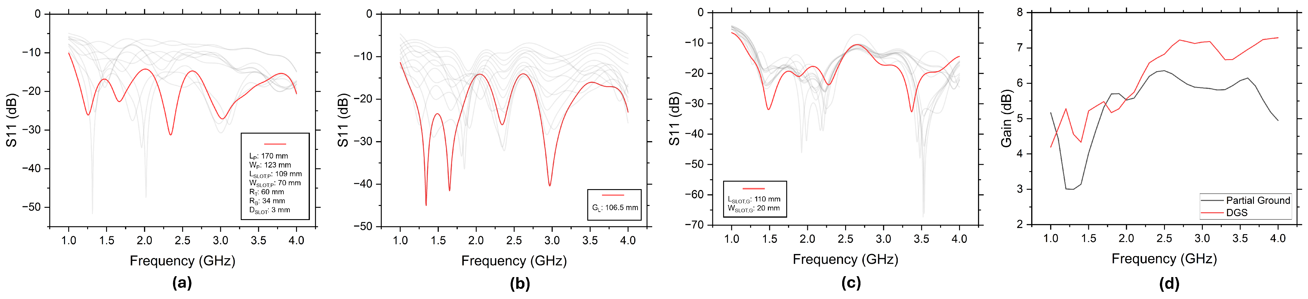
The dimensions of the inverted U-shaped patch, its rectangular slot, and the corner radii were optimised through iterative parametric simulations. The position and dimensions of the patch and slot, along with the corner radii ( & ), were adjusted to analyse their combined impact on antenna performance. The optimal dimensions of the inverted U-shaped patch antenna were determined through a simulation using a parametric optimisation process, ensuring minimal return loss at 1.5 GHz while maintaining wideband performance. The parameters were varied within practical ranges to achieve the best impedance matching and bandwidth characteristics, resulting in : 170 mm; : 123 mm; : 109 mm; : 70 mm; : 60 mm; : 34 mm; and : 3 mm. The corresponding simulated return loss performance is illustrated in Figure 1a.
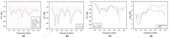
Figure 1.
(a) Simulated return loss (S11) of inverted U-shaped patch antenna with optimised dimensions. (b) Simulated return loss (S11) with optimised partial ground plane length (). (c) Simulated return loss (S11) of antenna with DGS. (d) Comparison of antenna gain between partial ground plane and DGS configuration. Note: The light gray lines in (a–c) show simulated return loss (S11) from parametric simulations, while the red line indicates the optimised return loss for the final dimensions.
To improve the impedance matching and bandwidth, the length of the partial ground plane, , was optimised by parametric studies. Minor adjustments to around the initial position were investigated to improve return loss. This optimisation process led to an optimal of 106.5 mm, resulting in a significant reduction in return loss, as shown in Figure 1b.
To further improve antenna performance, the impact of the DGS was analysed. Specifically, corner strip slots were introduced into the partial ground plane. The dimensions and positions of these slots were varied to optimise radiation efficiency, refine the radiation pattern, and increase the overall gain of the antenna. The resulting return loss and gain characteristics are presented in Figure 1c and Figure 1d, respectively. The simulation results show a significant gain improvement compared to the partial ground plane configuration.
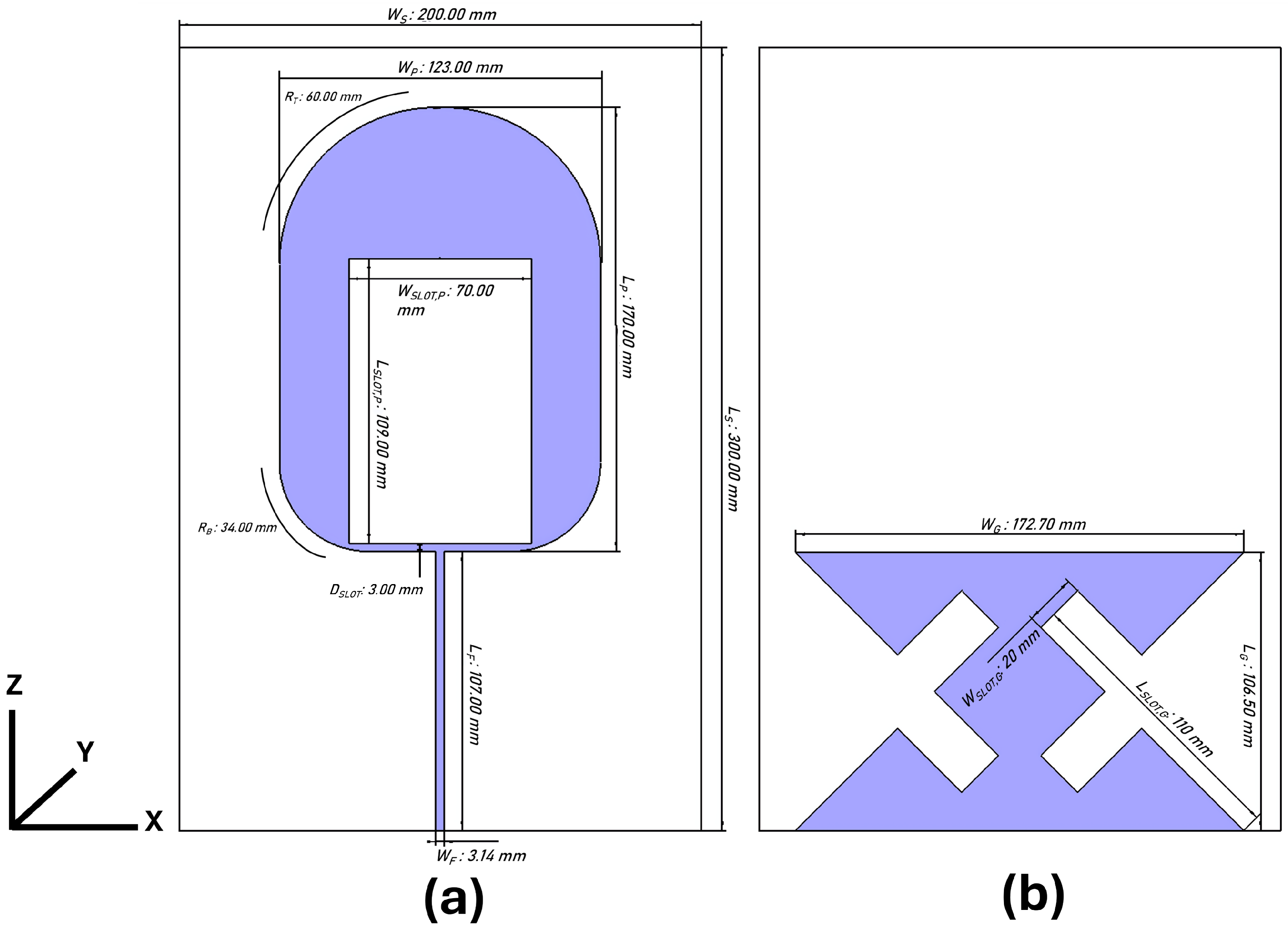
Table 1 summarises the optimised parameters for the proposed antenna design, derived from multiple simulation iterations aimed at achieving optimal performance. The antenna layout, showing the detailed geometry of the radiating patch and the modified ground plane, is given in Figure 2.

Table 1.
Optimised parameters for inverted U-shaped patch antenna design.
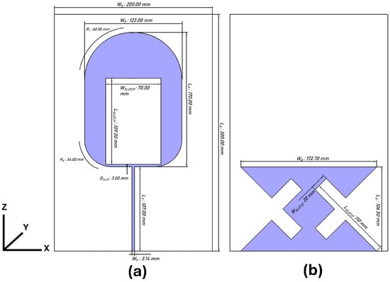
Figure 2.
Geometry of proposed antenna: (a) Radiating patch. (b) Defected ground structure.
3. Results
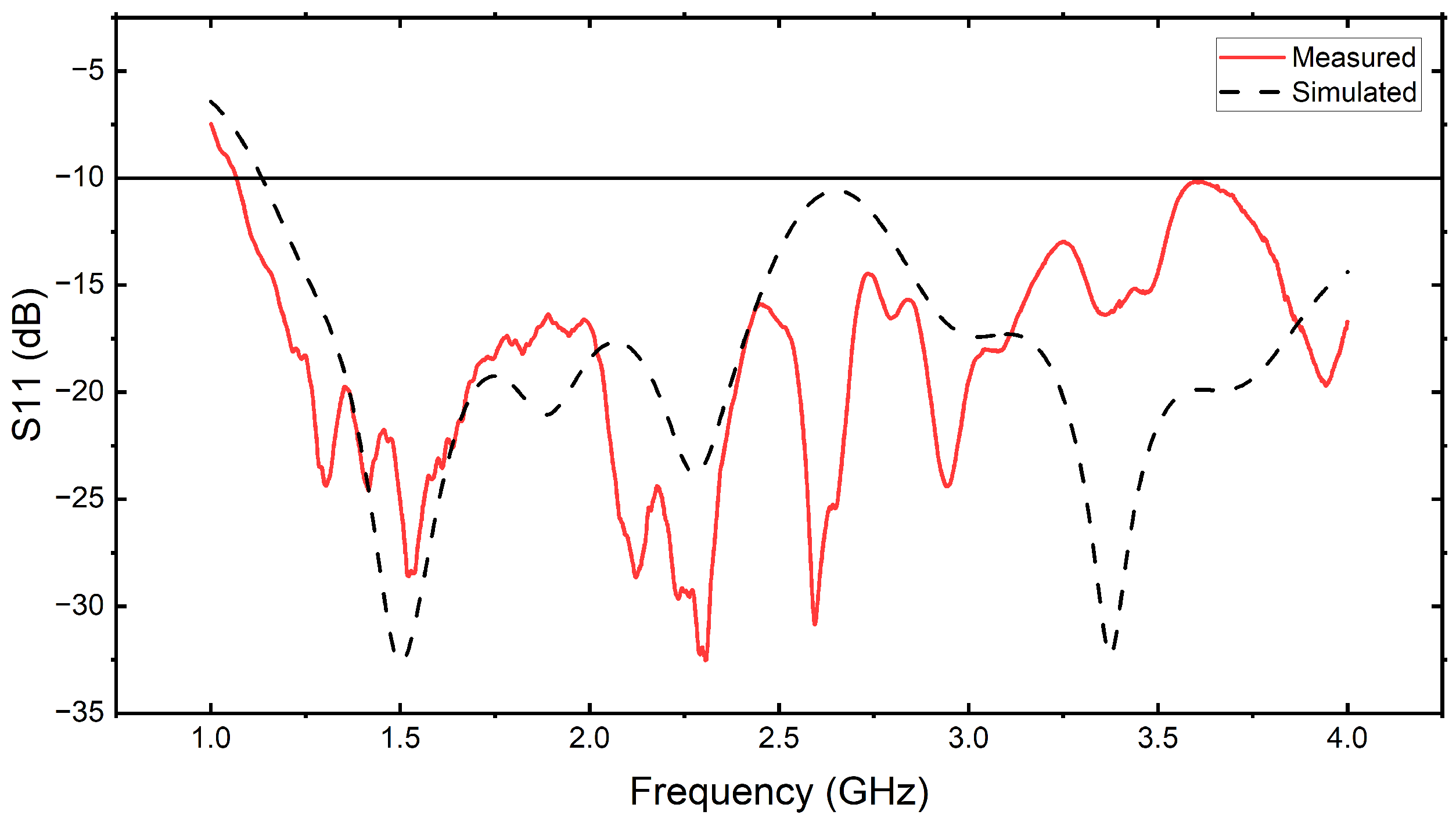
The antenna was simulated using a 50 waveguide, with the results demonstrating a bandwidth from 1.13 to 4 GHz at S11 < −10 dB. The minimum return loss is observed at 1.5 GHz (−32.62 dB) and 3 GHz (−32.32 dB).
The antenna was fabricated on an FR4 substrate to validate its real-world performance, as shown in Figure 3a, which shows the radiating patch, and Figure 3b, which illustrates the ground plane. Experimental measurements were performed using the Keysight FieldFox N9923A VNA. The results show that the antenna achieved a return loss below −10 dB in the operational frequency band from 1.068 to 4 GHz. A return loss below −20 dB is observed between 1.367 and 1.675 GHz, indicating minimal power reflection in this frequency range. Furthermore, the lowest return loss is observed at 2.30 GHz (−32.53 dB), while 1.52 GHz also exhibits a significant return loss of −28.60 dB.
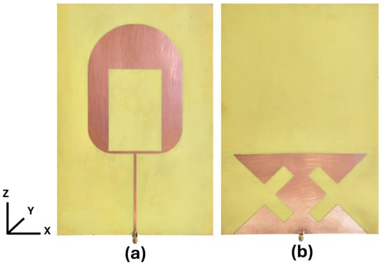
Figure 3.
Fabricated prototype of inverted U-shaped patch antenna: (a) Radiating patch. (b) Defected ground structure.
Figure 4 shows the simulated and measured return loss, demonstrating a close match between the design and the experimental results. Although the measured data align well with the simulations, minor differences may arise due to fabrication tolerances and variations in the FR4 material properties. Despite these variations, the measured bandwidth remains consistent with the simulations, confirming the expected antenna performance.
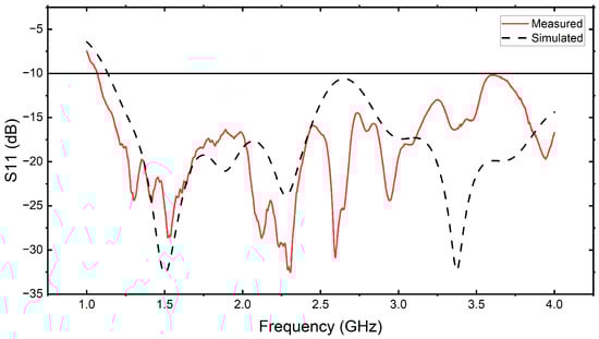
Figure 4.
Comparison of simulated and measured return loss (S11) of fabricated antenna.
Radiation Pattern
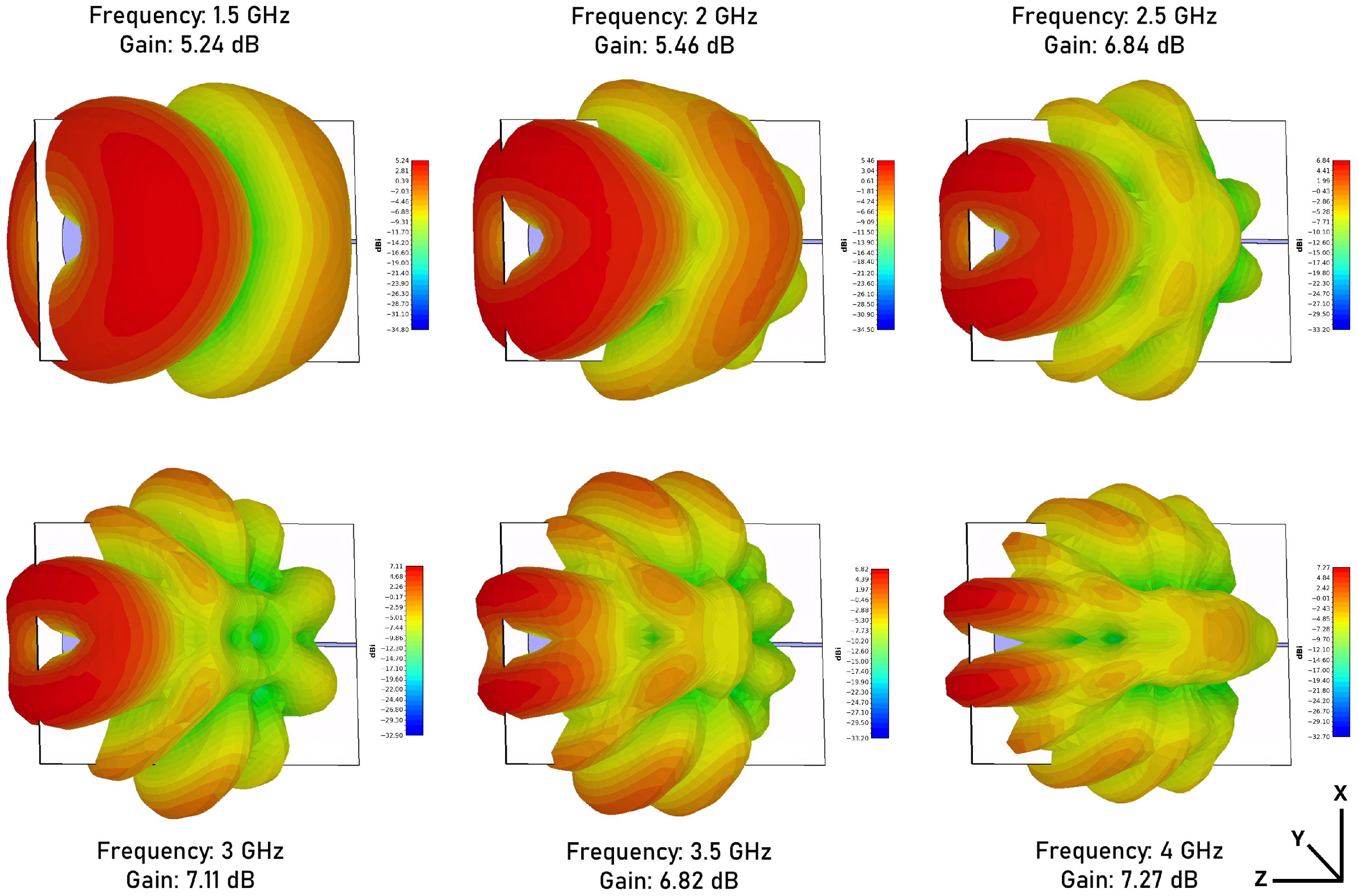
Figure 5 presents the simulated three-dimensional radiation patterns of the inverted U-shaped patch antenna in a frequency range of 1.5 to 4 GHz. The radiation pattern describes the distribution of the radiated power and provides insight into the antenna’s directional performance. The main lobe is directed along the z-axis, demonstrating strong radiation. The antenna achieves a gain of 5.24 dB at 1.5 GHz. As the frequency increases, the main lobe’s beamwidth decreases, indicating improved directivity. The gain peaks at 7.27 dB at 4 GHz. Additionally, the minor side lobe increases at higher frequencies. This behaviour is primarily due to the increase in the effective path length of the signal current, which is directly related to the operating wavelength.
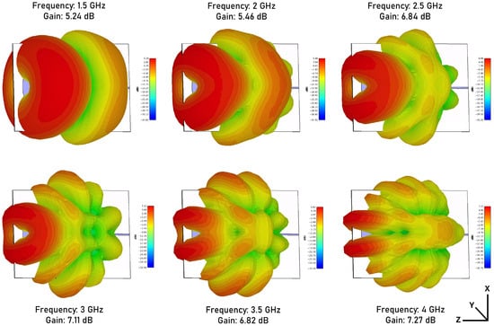
Figure 5.
The simulated 3D radiation patterns of the antenna at different operating frequencies (1.5 GHz, 2 GHz, 2.5 GHz, 3 GHz, 3.5 GHz, and 4 GHz). The corresponding peak gain values are indicated for each frequency, showing variations in radiation characteristics across the band.
4. Conclusions
This study presents the simulated and measured results of an Inverted U-shaped patch antenna centred at 1.5 GHz with a wide bandwidth of 1.068 to 4 GHz. The use of DGS improves the gain of the antenna, achieving 5.24 dB at 1.5 GHz and a peak gain of 7.27 dB at 4 GHz. A comparison between this study and previous research is provided in Table 2. The antenna achieves high gain without requiring a reflector, resulting in a more compact design compared to the reported designs. The antenna is scalable, and its gain can be further improved by adding a reflector. Its wide bandwidth and high gain make it suitable for GPR applications, enabling deeper penetration for utility mapping, landmine detection, and artefact detection. Additionally, its low cost, compact size, and ease of fabrication enhance its practicality for these applications. The authors of this study aim to improve the existing antenna design by reducing its dimensions, which will aid in improving its integration into compact GPR systems. Additionally, the design will be further optimised to improve the front-to-back (F/B) ratio by minimising side-lobe radiation, thereby enhancing its overall performance.
Table 2.
Comparison of antenna designs and performance metrics from previous studies.
Author Contributions
Conceptualisation, A.J.K.; methodology, A.J.K.; writing—original draft preparation, A.J.K.; writing—review and editing, A.J.K., N.B. and U.S.; resources, N.B. and U.S.; visualisation, A.J.K.; supervision, U.S. All authors have read and agreed to the published version of the manuscript.
Funding
This research received no external funding.
Institutional Review Board Statement
Not applicable.
Informed Consent Statement
Not applicable.
Data Availability Statement
The data are contained within the article.
Acknowledgments
The authors would like to acknowledge the Department of Science and Technology, India, for supporting Ankur Jyoti Kalita through the INSPIRE Fellowship program. The authors also express their sincere gratitude and deep appreciation to Pranjal Borah of the Department of Instrumentation & USIC, Gauhati University, India, for his invaluable guidance and insights on antenna design and optimisation.
Conflicts of Interest
The authors declare no conflicts of interest.
References
- Jol, H.M. Ground Penetrating Radar Theory and Applications; Elsevier: Amsterdam, The Netherlands, 2008. [Google Scholar]
- Ali, H.; Ideris, N.S.M.; Zaidi, A.A.; Azalan, M.Z.; Amran, T.T.; Ahmad, M.; Rahim, N.A.; Shukor, S.A. Ground penetrating radar for buried utilities detection and mapping: A review. J. Phys. Conf. Ser. 2021, 2107, 012056. [Google Scholar]
- Pryshchenko, O.A.; Plakhtii, V.; Dumin, O.M.; Pochanin, G.P.; Ruban, V.P.; Capineri, L.; Crawford, F. Implementation of an artificial intelligence approach to GPR systems for landmine detection. Remote Sens. 2022, 14, 4421. [Google Scholar] [CrossRef]
- Manataki, M.; Vafidis, A.; Sarris, A. GPR data interpretation approaches in archaeological prospection. Appl. Sci. 2021, 11, 7531. [Google Scholar] [CrossRef]
- Spears, M.; Hedjazi, S.; Taheri, H. Ground penetrating radar applications and implementations in civil construction. J. Struct. Integr. Maint. 2023, 8, 36–49. [Google Scholar] [CrossRef]
- Ding, C.; Li, J.; Hu, R. Moon-based ground-penetrating radar observation of the latest volcanic activity at the Chang’E-4 landing site. IEEE Trans. Geosci. Remote Sens. 2023, 61, 4600410. [Google Scholar]
- Hamran, S.E.; Paige, D.A.; Amundsen, H.E.; Berger, T.; Brovoll, S.; Carter, L.; Damsgård, L.; Dypvik, H.; Eide, J.; Eide, S.; et al. Radar imager for Mars’ subsurface experiment—RIMFAX. Space Sci. Rev. 2020, 216, 128. [Google Scholar] [CrossRef]
- Casademont, T.M.; Dypvik, H.; Eide, S.; Berger, T.; Hamran, S.E. Martian ground penetrating radar: Towards automated diffraction detection for dielectric permittivity. IEEE Trans. Geosci. Remote Sens. 2024, 62, 4511210. [Google Scholar]
- Ciarletti, V.; Corbel, C.; Plettemeier, D.; Cais, P.; Clifford, S.M.; Hamran, S.E. WISDOM GPR designed for shallow and high-resolution sounding of the Martian subsurface. Proc. IEEE 2011, 99, 824–836. [Google Scholar] [CrossRef]
- Guan, W.; Su, Y.; Li, J.; Dai, S.; Ding, C.; Liu, Y. Applications of ground-penetrating radar in asteroid and comet exploration. Remote Sens. 2024, 16, 2188. [Google Scholar] [CrossRef]
- Hertl, I.; Strycek, M. UWB antennas for ground penetrating radar application. In Proceedings of the 2007 19th International Conference on Applied Electromagnetics and Communications, Dubrovnik, Croatia, 24–26 September 2007; pp. 1–4. [Google Scholar]
- Ali, J.; Abdullah, N.; Ismail, M.Y.; Mohd, E.; Shah, S.M. Ultra-wideband antenna design for GPR applications: A review. Int. J. Adv. Comput. Sci. Appl. 2017, 8, 392–400. [Google Scholar] [CrossRef]
- Chakrabarti, N.; Kalra, S.; Saxena, S.; Tripathy, M.R. Ultra-wideband antenna for a ground penetrating radar. In Proceedings of the 2016 Thirteenth International Conference on Wireless and Optical Communications Networks (WOCN), Hyderabad, India, 21–23 July 2016; pp. 1–6. [Google Scholar]
- Sutham, T.; Thaiwirot, W.; Akkaraekthalin, P. Design of Ultra-Wideband Inverted U-Shaped Slot Antenna with Reflector for GPR Applications. In Proceedings of the 2022 19th International Conference on Electrical Engineering/Electronics, Computer, Telecommunications and Information Technology (ECTI-CON), Prachuap Khiri Khan, Thailand, 24–27 May 2022; pp. 1–4. [Google Scholar]
- Balanis, C.A. Antenna Theory: Analysis and Design; John Wiley & Sons: Hoboken, NJ, USA, 2015. [Google Scholar]
- Travassos, X.; Avila, S.; Adriano, R.d.S.; Ida, N. A review of ground penetrating radar antenna design and optimization. J. Microw. Optoelectron. Electromagn. Appl. 2018, 17, 385–402. [Google Scholar] [CrossRef]
- Abdelgwad, A.H. Microstrip patch antenna enhancement techniques. Int. J. Electron. Commun. Eng. 2018, 12, 703–710. [Google Scholar]
- Cao, P.; Huang, Y.; Zhang, J. A UWB monopole antenna for GPR application. In Proceedings of the 2012 6th European Conference on Antennas and Propagation (EUCAP), Prague, Czech Republic, 26–30 March 2012; pp. 2837–2840. [Google Scholar]
- Ismail, O.; Youssef, L.; Otman, O.; Aghanim, A. Design of a Circular Patch Antenna with a reflector for GPR applications. ITM Web Conf. 2022, 48, 01004. [Google Scholar]
- Khalid, N.; Ibrahim, S.; Karim, M. Directional and wideband antenna for ground penetrating radar (GPR) applications. In Proceedings of the 2016 3rd International Conference on Electronic Design (ICED), Phuket, Thailand, 11–12 August 2016; pp. 203–206. [Google Scholar]
- Karim, M.A.; Malek, M.F.; Jamlos, M.; Seng, L.; Saudin, N. Design of ground penetrating radar antenna for buried object detection. In Proceedings of the 2013 Ieee International Rf and Microwave Conference (RFM), Penang, Malaysia, 9–11 December 2013; pp. 253–257. [Google Scholar]
- Trivedi, D.; Gotra, S.; Phartiyal, G.S.; Singh, D. An Ultra-Wideband Dual-layer Microstrip Planar Antenna for Radar Imaging System. In Proceedings of the 2022 IEEE Conference on Antenna Measurements and Applications (CAMA), Guangzhou, China, 14–17 December 2022; pp. 1–4. [Google Scholar]
- Raza, A.; Lin, W.; Chen, Y.; Yanting, Z.; Chattha, H.T.; Sharif, A.B. Wideband tapered slot antenna for applications in ground penetrating radar. Microw. Opt. Technol. Lett. 2020, 62, 2562–2568. [Google Scholar]
- Raza, A.; Lin, W.; Ishfaq, M.; Inam, M.; Masud, F.; Dahri, M. A Wideband Reflector-Backed Antenna for Applications in GPR. Int. J. Antennas Propag. 2021, 2021, 3531019. [Google Scholar]
- Nayak, R.; Maiti, S.; Patra, S.K. Design and simulation of compact UWB Bow-tie antenna with reduced end-fire reflections for GPR applications. In Proceedings of the 2016 International Conference on Wireless Communications, Signal Processing and Networking (WiSPNET), Chennai, India, 23–25 March 2016; pp. 1786–1790. [Google Scholar]
- Wu, Y.; Shen, F.; Yuan, Y.; Xu, D. An improved modified universal ultra-wideband antenna designed for step frequency continuous wave ground penetrating radar system. Sensors 2019, 19, 1045. [Google Scholar] [CrossRef] [PubMed]

Disclaimer/Publisher’s Note: The statements, opinions and data contained in all publications are solely those of the individual author(s) and contributor(s) and not of MDPI and/or the editor(s). MDPI and/or the editor(s) disclaim responsibility for any injury to people or property resulting from any ideas, methods, instructions or products referred to in the content. |
© 2025 by the authors. Licensee MDPI, Basel, Switzerland. This article is an open access article distributed under the terms and conditions of the Creative Commons Attribution (CC BY) license (https://creativecommons.org/licenses/by/4.0/).