Proceeding Paper

Development of Jaw Controlled Wireless Navigation Governing System for Wheelchair to Empower Person with Impaired Upper Limb †

by
Dhanasekar Ravikumar
*,
Vijayaraja Loganathan
,
Narenthira Sai Raam Pasumponthangaperumal
*,
Mirthulaa Suresh Kumar
,
Pranav Ponnovian
and
Benita Evangeline Balan
Department of Electrical and Electronics Engineering, Sri Sairam Institute of Technology, Chennai 600044, Tamilnadu, India
*
Authors to whom correspondence should be addressed.
The 5th International Electronic Conference on Applied Sciences, 4–6 December 2024; Available online: https://sciforum.net/event/ASEC2024.
Eng. Proc. 2025, 87(1), 10; https://doi.org/10.3390/engproc2025087010
Published: 28 February 2025
(This article belongs to the Proceedings of The 5th International Electronic Conference on Applied Sciences)

Abstract

The central focus of this work is to implement an effective and cost-friendly wheelchair motion control system for individuals with impaired upper body movements by utilizing the mandibular movement of an individual. The initial part of the system is the signal-gathering system that is built of two functional blocks, the magnet and sensing block. A magnet is affixed to the inferior region of the user’s mandible, and the sensing block, which incorporates two static HMCL 5883L sensors, quantifies the magnetic field intensity modulated by the magnet’s displacement. The processing unit deciphers these sensor signals to ascertain the wheelchair’s trajectory, while the mechanical unit affects the movement directives. The methodology is embedding the HMCL 5883L sensor into the microcontroller to detect the required motion for the wheelchair. The HMCL 5883L sensors are incorporated to identify each change in the orientation of the magnet. HMCL 5883L is a sophisticated and budget technology. The sensor partitions the magnet’s strength path into three hypothetical axes to trace the magnet in the user’s jaw region. The magnet’s configuration in the mandibular region will not create unease, and a user jaw action that requires a certain level is not new. This development empowers the mobility of patients with Quadriplegia, and because of the device’s smaller footprint and feasible modules, it infuses sustainable development and availability.

1. Introduction

People with disabilities are common all around the world. A disabled person with an impaired upper limb is faced with mobility or forced to use a wheelchair for movement. Mobility plays a vital role in the life of an individual. Those people’s major challenge in a conventional wheelchair is to depend on an assistive person for navigation and directional changes. New technologies must be developed with easy availability, user-friendly experience, and feasibility to overcome this problem. The mechanical energy required for an automatic wheelchair is provided by an electrical motor. Using a brushless direct current motor is an optimized way to improve the wheelchair’s performance [1]. The way of introducing a mandibular control system for a wheelchair navigation system is highly practical and effective [2,3]. Even advanced methodology is a brain-controlled wheelchair motion control mechanism designed so that the direction of the wheelchair is determined by the neurological signal transmitted by the brain. Each signal is assigned to a specific command to execute a pre-determined motion [4]. An emerging technology to be acknowledged is artificial intelligence (AI), which is based on navigation systems that increase the mobility of individuals in all forms of transportation [5]. The method of using the tongue as a joystick to provide instruction for an electric-powered wheelchair is a common development in the automation of electric wheelchairs; it introduces a magnet on the surface of the tongue and a sensor outside the mouth region mounted on a head-supported attachment or an orthodontic band around the head [6,7,8,9,10]. IoT-infused wheelchairs that are cost-effective and low maintenance have large applications in remote areas, and the addition of biophysical sensors and AI health monitoring technologies provides a variety of positive commitments [11,12,13]. A more specific form of illness that requires wheelchair assistance is Quadriplegia; it is a paralysis that disables the person to move to interact with their own muscles that are under the person’s neck region. A cutting-edge method of using both head and tongue to navigate the smart wheelchair is designed and tested among patients for trails and user interface capabilities [14,15].

2. The Proposed Wheelchair Control System

The proposed system has a cost-effective build to maximize its availability. The system’s architecture consists of three functional units. The units are as follows:
  • Data collection unit;
  • Data processing unit and source;
  • Mechanical unit.
These three units have unique components and functions. The block diagram of the proposed system with a cross-section of each unit is picturized in Figure 1.

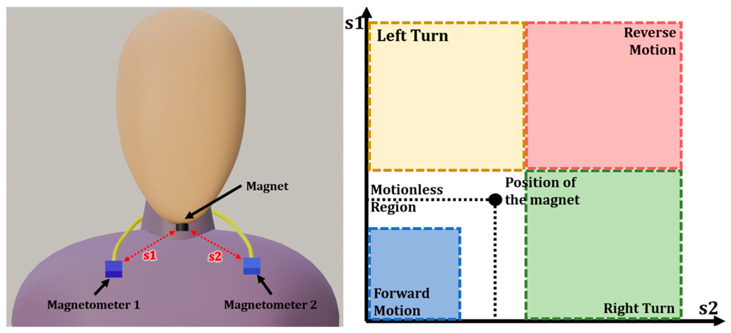
2.1. Data Collection Unit

The main objective of the system’s data collection unit is to measure the magnetic intensity of the magnet. This system compresses the two magnetometers placed on opposite sides for a three-dimensional location calculation system. The magnetometer used in the system is HMCL 5883L (Honeywell Aerospace, Phoenix, AZ, USA). The magnetometers are calibrated with the intensity of the magnet to provide the instruction. The magnetometers are stationary and measure the magnetic strength of the magnet from both sides to have four directional motions, as shown in Figure 2.
Let the distance between the magnet and the magnetometer 1 be s1.
Let the distance between the magnet and the magnetometer 2 be s2.
As the distance between the magnetometer and the magnet increases, the magnetic intensity measured by the sensor decreases. As the distance between the sensor and the magnet decreases, the magnetic intensity increases. The closer the magnet is to the sensor, the higher the magnetic intensity. Table 1 Shows the dimensions of the magnetometer sensor.
The magnetometer sensor will be placed on an elastic band that can be worn around the neck. It will be perpendicular to the person’s neck and below the mandibular region of the person. Each sensor will be 45° inclined to the magnet.
In Figure 2, the instruction for the wheelchair to stay stationary is shown as a standard position of a human mandibular region. At this condition, the values of s1 and s2 are almost equal, and as shown in the graph, the magnet remains in the Motionless Region.

2.2. Data Processing Unit and Source

The data processing unit consists of an Arduino UNO as the microcontroller or brain of the system. The microcontroller receives the readings of both the magnetometer and determines the assigned instruction to perform. The signal to execute the assigned command is given to the isolation circuit.
In Figure 3, the distance between the magnetometers and the magnet is minimal. So, the magnetic intensity will be maximum. The values of s1 and s2 decrease as the person tilts their mandibular forward, reducing the distance between the magnet and sensor and resulting in forward motion. The distance between both the magnetometers and the magnet is maximum, so the magnetic intensity will be minimum. The values of s1 and s2 increase as the person tilts their mandibular backward, increasing the distance between the magnet and sensor and resulting in reverse motion.
In Figure 4, the instruction for a left turn is to turn the person’s mandible to the left side. As the mandibular turns to the left side, the distance between the magnetometer 1 and the magnet increases, and the distance between the magnetometer 2 and the magnet decreases. So, the value of s1 will be much higher than the value of s2, resulting in a left turn of the wheelchair. The instruction for a right turn is to turn the person’s mandible to the right side. As the mandibular turns to the right side, the distance between the magnetometer 1 and the magnet decreases, and the distance between the magnetometer 2 and the magnet increases. So, the value of s1 will be much lower than the value of s2, resulting in the right turn of the wheelchair.

2.3. Mechanical Unit

The primary function of the mechanical unit is to convert the electrical signal from the microcontroller into mechanical energy. It consists of an Isolation/Driver circuit and a pair of motors. The Isolation/Driver circuit isolates the motor from the electronics and also regulates the speed and direction of each motor. Each motor rotates according to the condition of the microcontroller. The motor will rotation is determined by the magnetic intensity of the magnet from both the magnetometer.
In case of direction changes, the motor in the respective direction will slow down, and the motor on the adjacent side will speed up, resulting in a direction change. For example, for a left turn, motor 1 will reduce its speed, and motor 2 will increase its speed, slowly turning the wheelchair to the left side. Table 2 presents the speed and direction of each in every condition.

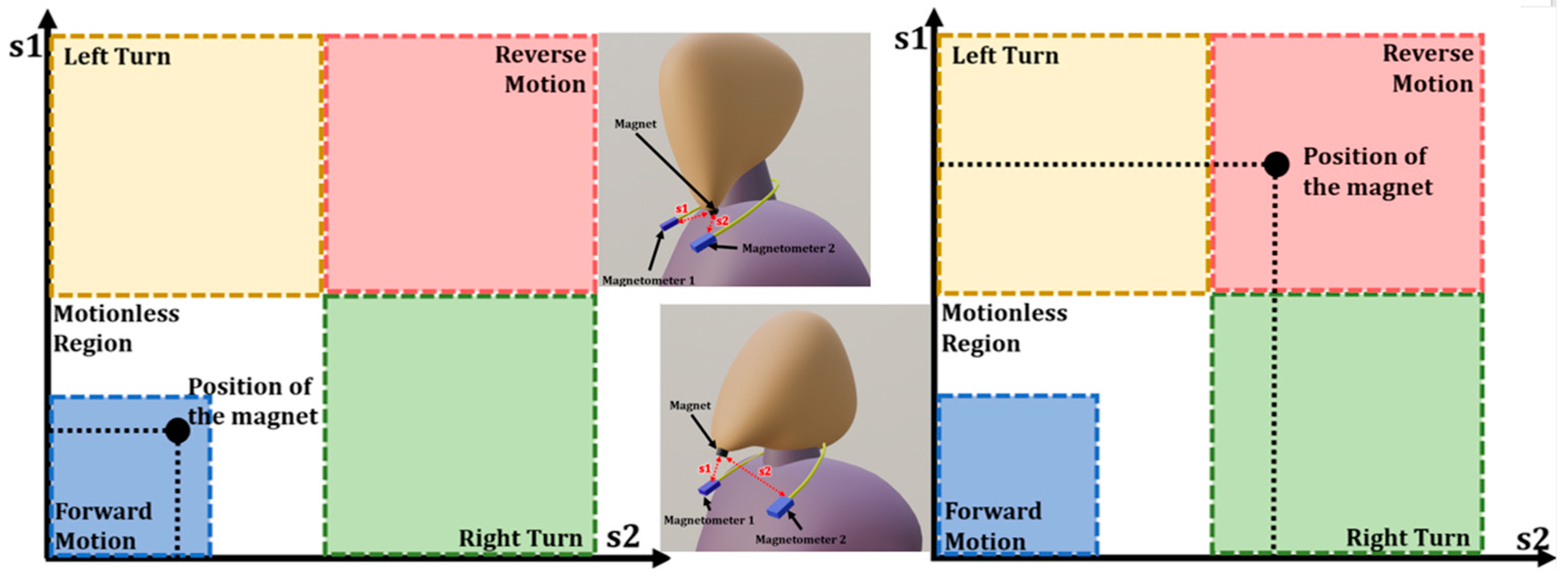
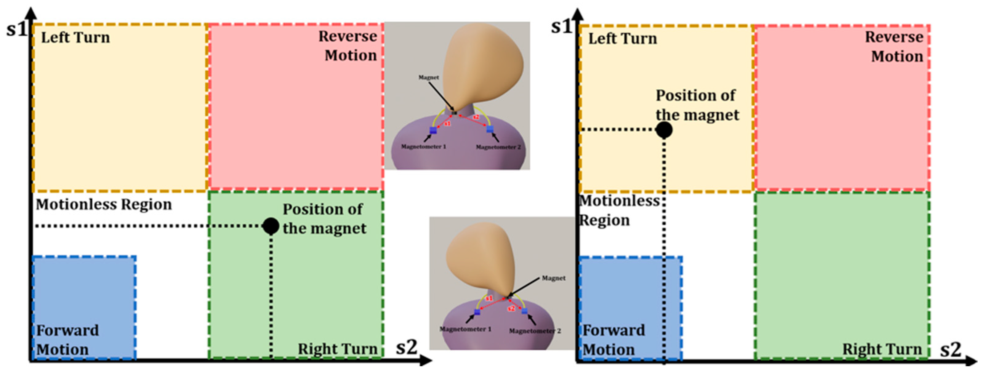
3. Working Process of the Proposed Wheelchair Control System

Figure 5 elaborates on data flow from the start of the system to the final output of the system.

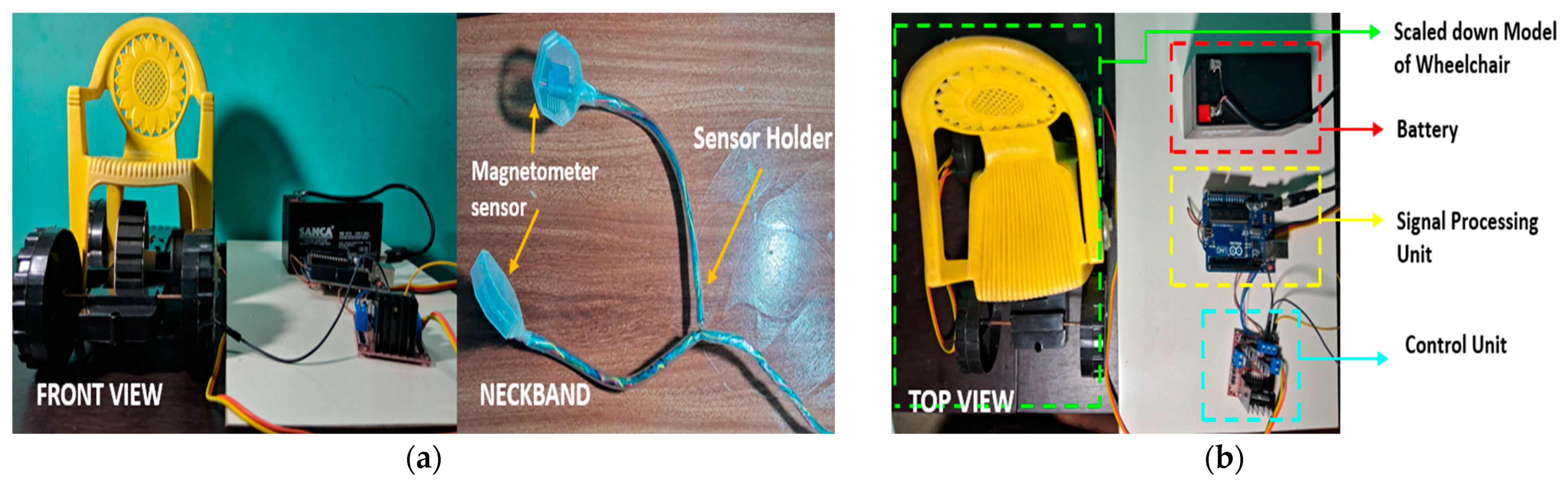
4. Hardware Setup for the Proposed Control System

Figure 6a shows the hardware setup of the proposed system with a scaled-down model of a wheelchair. Figure 6b shows the hardware description of the proposed system. The two magnetometer sensors are mounted on a sensor holder in an elastic neckband. This neckband will be set around the neck and will remain stationary. The magnet will attach to the bottom of the mandibular region of a human using the suction pad, as the suction pad does not cause irritation or discomfort for the person. As Mandibular motion is a daily basic movement pattern, it will be easy for disabled people and persons with Quadriplegia to learn the instructions of the system.
The electronic components utilized on the proposed hardware, along with its description, are given in Table 3.
The motor used in the system is MY1016, which is a small, lightweight motor, and the specifications of the motor are shown in Table 4.
The proposed system heavily focuses on mandibular control rather than tongue control to ensure safety for children. The architecture of the proposed system is simple and flexible; it can also be installed in a conventional wheelchair with ease. The two electrical motors are attached below the chair, and the motor controls the rear wheels of the wheelchair.
A concise comparative analysis was conducted for the proposed wheelchair control system alongside two other wheelchair control systems. The comparison focused on three key factors: cost-effectiveness, comfort, and the level of manual assistance required for optimal functionality. Cost-effectiveness was prioritized as a critical business consideration, while comfort was emphasized due to the extended periods users spend in wheelchairs. The need for manual assistance was also evaluated to assess the system’s operational efficiency. The first system analyzed was a traditional wheelchair, which lacks electronic components to enhance reliability. While it is the most affordable option, it falls short in terms of comfort and requires constant manual assistance, making it less cost-effective in the long run. The second system, the proposed wheelchair, incorporates essential electronic components to improve reliability and durability. It strikes a balance between cost-effectiveness and comfort, requiring minimal manual assistance only in critical situations. The third system, a high-end wheelchair control system, utilizes advanced electronic components and premium materials, resulting in significantly higher costs. This detailed comparison is visually represented in Figure 7 for clarity and ease of understanding.

5. Conclusions

The proposed Wheelchair control system introduces a mandibular control mechanism using common and in-expensive electronics. The use of HMCL 5883L and Arduino UNO as the key components allows the system to be easily integrated with additional healthcare sensors and technologies to improve the functionality of the wheelchair. Providing a system with simple and effective architecture enhances its ability to be attached to traditional wheelchairs and can be installed on manual wheelchairs, making automatic wheelchairs. This system can replace the existing tongue-driven automated wheelchair control system as tongue control is not as optimized and unchallenging control system as the mandibular controlled system. The way of providing four directional mobility with any assistance can heavily improve the transportation of people with disability and Quadriplegia. Quadriplegia paralysis is the whole body below the neck region. The proposed system does not require any motion or action from the lower limp of a human. In the future, closed-loop motor control can be implemented to enhance the stability and responsiveness of the system.

Author Contributions

Conceptualization, N.S.R.P. and D.R.; methodology, M.S.K. and V.L.; software, P.P. and B.E.B.; validation, all of the authors; investigation, all of the authors; writing—original draft preparation, all of the authors; writing—review and editing and supervision, D.R. and N.S.R.P. All authors have read and agreed to the published version of the manuscript.

Funding

This research received no external funding.

Institutional Review Board Statement

Not applicable.

Informed Consent Statement

Not applicable.

Data Availability Statement

Data is contained within the article.

Conflicts of Interest

The authors declare no conflicts of interest.

References

  1. Gottipati, P.; Dobzhanskyi, O.; Mendrela, E.A. In-wheel brushless DC motor for a wheel chair drive. In Proceedings of the 2010 Joint International Conference on Power Electronics, Drives and Energy Systems & 2010 Power India, New Delhi, India, 20–23 December 2010; pp. 1–4. [Google Scholar] [CrossRef]
  2. Wang, Q.; Chen, H.; Wu, W.; Jin, H.Y.; Heng, P.A. Real-Time Mandibular Angle Reduction Surgical Simulation With Haptic Rendering. IEEE Trans. Inf. Technol. Biomed. 2012, 16, 1105–1114. [Google Scholar] [CrossRef] [PubMed]
  3. Tang, T.; Zhu, M.; Chen, C.; Xu, Y. A Design of Mandibular Motion Tracking System Based on Video Processing. In Proceedings of the 2019 IEEE 4th Advanced Information Technology, Electronic and Automation Control Conference (IAEAC), Chengdu, China, 20–22 December 2019; pp. 1370–1374. [Google Scholar] [CrossRef]
  4. Shahin, M.K.; Tharwat, A.; Gaber, T.; Hassanien, A.E. A wheelchair control system using human-machine interaction: Single-modal and multimodal approaches. J. Intell. Syst. 2019, 28, 115–132. [Google Scholar] [CrossRef]
  5. Bokolo, A.J. Inclusive and safe mobility needs of senior citizens: Implications for age-friendly cities and communities. Urban Sci. 2023, 7, 103. [Google Scholar] [CrossRef]
  6. Huo, X.; Wang, J.; Ghovanloo, M. Wireless control of powered wheelchairs with tongue motion using tongue drive assistive technology. In Proceedings of the 2008 30th Annual International Conference of the IEEE Engineering in Medicine and Biology Society, Vancouver, BC, Canada, 20–25 August 2008; pp. 4199–4202. [Google Scholar]
  7. Krishnamurthy, G.; Ghovanloo, M. Tongue drive: A tongue operated magnetic sensor based wireless assistive technology for people with severe disabilities. In Proceedings of the 2006 IEEE international symposium on circuits and systems, Kos, Greece, 21–24 May 2006; p. 4. [Google Scholar]
  8. Acosta, D.; Fariña, B.; Toledo, J.; Sanchez, L.A. Low Cost Magnetic Field Control for Disabled People. Sensors 2023, 23, 1024. [Google Scholar] [CrossRef] [PubMed]
  9. Faria, B.M.; Reis, L.P.; Lau, N. A survey on intelligent wheelchair prototypes and simulators. In New Perspectives in Information Systems and Technologies; Springer International Publishing: Berlin/Heidelberg, Germany, 2014; Volume 1, pp. 545–557. [Google Scholar]
  10. Caltenco, H.A.; Breidegard, B.; Andreasen Struijk, L.N. On the tip of the tongue: Learning typing and pointing with an intra-oral computer interface. Disabil. Rehabil. Assist. Technol. 2014, 9, 307–317. [Google Scholar] [CrossRef] [PubMed]
  11. Dar, R.A.; Khatoon, S.; Saleem, B.; Khan, H. IOT Based Smart Wheelchair for Elderly Healthcare Monitoring. In Proceedings of the 2023 International Conference on Power, Instrumentation, Energy and Control (PIECON), Aligarh, India, 10–12 February 2023; pp. 1–6. [Google Scholar]
  12. Al Shabibi, M.A.K.; Kesavan, S.M. Iot based smart wheelchair for disabled people. In Proceedings of the 2021 International Conference on System, Computation, Automation and Networking (ICSCAN), Puducherry, India, 30–31 July 2021; pp. 1–6. [Google Scholar]
  13. Dwivedi, A.; Kumar, R.; Omer, P.; Singh, H.P.; Rahmani, U.; Gupta, K. Electric Wheelchair for Physically Disabled Person. In Proceedings of the 2023 International Conference on IoT, Communication and Automation Technology (ICICAT), Gorakhpur, India, 23–24 June 2023; pp. 1–6. [Google Scholar]
  14. Sebkhi, N.; Bhavsar, A.; Sahadat, N.; Baldwin, J.; Walling, E.; Biniker, A.; Hoefnagel, M.; Tonuzi, G.; Osborne, R.; Anderson, D.V.; et al. Evaluation of a head-tongue controller for power wheelchair driving by people with quadriplegia. IEEE Trans. Biomed. Eng. 2021, 69, 1302–1309. [Google Scholar] [CrossRef] [PubMed]
  15. Huang, C.K.; Wang, Z.W.; Chen, G.W.; Yang, C.Y. Development of a smart wheelchair with dual functions: Real-time control and automated guide. In Proceedings of the 2017 2nd International Conference on Control and Robotics Engineering (ICCRE), Bangkok, Thailand, 1–3 April 2017; pp. 73–76. [Google Scholar]
Figure 1. Block diagram of the proposed wheelchair control system.
Engproc 87 00010 g001
Figure 2. Instruction and graphical position of the magnet for a motionless condition.
Engproc 87 00010 g002
Figure 3. Instruction and graphical position of the magnet for forward and reverse motion.
Engproc 87 00010 g003
Figure 4. Instruction and graphical position of the magnet for a left and right turn condition.
Engproc 87 00010 g004
Figure 5. Flow Chart of the Proposed Control System.
Engproc 87 00010 g005
Figure 6. Hardware model of Proposed System: (a) Front view of the hardware setup and the sensor neckband; (b) Hardware Description of the Proposed System.
Engproc 87 00010 g006
Figure 7. Characteristic comparison of the proposed system with existing systems.
Engproc 87 00010 g007
Table 1. The dimensions of the magnetometer sensor.
SpecificationDimensions
Length (mm)14.8
Width (mm)13.5
Height (mm)3.5
Weight (mm)2
Table 2. Characteristic of the motors for each condition.
ConditionMotor 1Motor 2
Direction of RotationSpeed of the Motor (% of Max Speed)Direction of RotationSpeed of the Motor (% of Max Speed)
Forward MotionForward90Forward90
Reverse MotionReverse60Reverse60
Left TurnForward40Forward100
Right TurnForward100Forward40
Table 3. Component description of hardware.
Component NameComponent Description
Arduino UNOMicrocontroller
HMCL 5883LMagnetometer Sensor
L298N-2AIsolation/Driver Circuit
MY1016Motor
Samarium CobaltMagnet
BatteryLithium-ion battery
Table 4. Specification of the Motor MY1016.
SpecificationDescription
Output Power24 W
Supply Voltage12 V
Rated Speed2200 RPM
No Load Speed2500 RPM
Full Load Current<1.5 A
No Load Current<0.5 A
Disclaimer/Publisher’s Note: The statements, opinions and data contained in all publications are solely those of the individual author(s) and contributor(s) and not of MDPI and/or the editor(s). MDPI and/or the editor(s) disclaim responsibility for any injury to people or property resulting from any ideas, methods, instructions or products referred to in the content.

