Abstract
The IDEA project, developed in the frame of MOST—National Centre for Sustainable Mobility—addressed the growing need for reliable bonded joints in fibre-reinforced polymer composite structures used in transportation. Purely bonded joints are preferred for their lightweight and cost-efficient properties, but contamination and defect detection issues often make them unreliable. To solve this, the project developed innovative surface treatments, a methodology for the safe, optimized design of bonded joints, and structural health monitoring solutions, viable for real-time assessment. These advancements aim to increase the reliability and safety of bonded connections, helping industries adopt lighter, purely bonded joints over heavier, hybrid bonded/bolted options.
1. Introduction
Bonded joints in composite parts are crucial in the design of transportation systems, from automotive to aerospace. Designing these joints to resist static and fatigue failure is complex, and no industrial standard exists. Detecting defects like poor bonding caused by contaminants during manufacturing is challenging, limiting the certifiability of purely bonded joints for primary components. This uncertainty forces companies to use heavier, more expensive hybrid bonded/bolted solutions. To replace these with fully bonded joints, the IDEA project aimed to develop an industrial-scale methodology for the production, design, and monitoring of bonded joints, ensuring safety and reliability. The main objectives are as follows:
- ○
- Implement an innovative pre-bonding surface treatment using chemical etching and scale the process to the industrial level. Lab tests will evaluate surface conditions and joint properties, followed by large-scale validation.
- ○
- Develop a structural design methodology for reliable bonded joints using a local approach and sub-modelling strategy, turning it into an industrial tool.
- ○
- Create a structural health monitoring (SHM) system based on thermographic techniques to ensure in-service safety and scalability to real components.
The initial phase optimized the etching process for two material combinations, assessing surface roughness and testing single-lap joints. The optimal parameters were then adapted for larger-scale applications, including producing specimens and a prototype panel–stringer connection. Quasi-static and fatigue tests examined the effects of the scaled etching on joint performance. A modelling strategy for local stress fields was validated against the experimental data. Finally, SHM strategies using viable in-service sensors were applied and tested.
2. Etching Optimization and Process Scale-Up
2.1. Identification of the Optimal Etching Parameters
Chemical etching using 97% sulfuric acid (H2SO4) was chosen due to its effectiveness in removing contaminants from CFRP surfaces, enhancing bond strength [1,2]. Two material systems were tested:
- ○
- MAT1: Adherends CC204 6K T800 T2/2 ER451; adhesive DP490.
- ○
- MAT2: Adherends C380 T700 2X2T; adhesive Betamate 2098.
The impact of acid concentration, etching temperature, and duration on bond strength was assessed using single-lap specimens. The acid was applied either by pipette or soaking of a single 20 mm width specimen, with shear strength and surface roughness measured after the treatment. The soaking method after the surface polishing and cleaning proved most effective, and optimal parameters were established for both systems: a 60% acid concentration at 60 °C for 5 min.
2.2. Process Scale-Up and Application to a Component Prototype
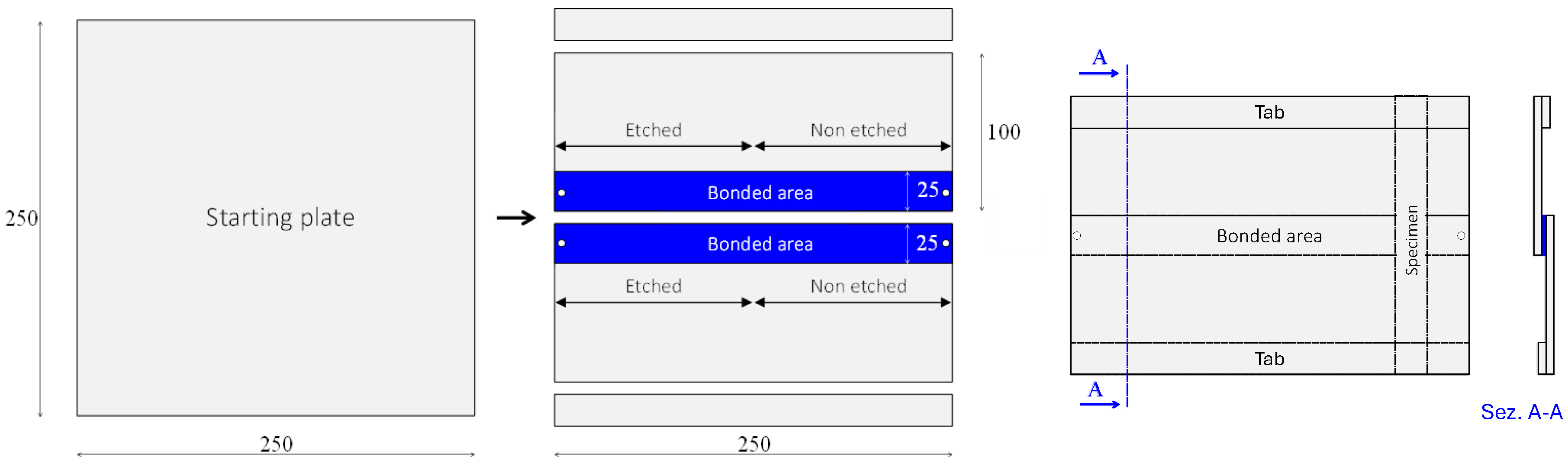
After optimization, the etching process was scaled up for larger panels (Figure 1), and joints were created by bonding halves of the panels along their long sides. Etching was applied to only half of the plate’s width, and shear tests were performed. It was found that both the pipette and soaking methods were unsuitable for large areas due to uneven acid distribution, so a brush was used for a uniform application. The bonding process involved cutting plates, cleaning, etching, and curing at 60 °C for 2 h under pressure. Calibrated glass spheres were added to control adhesive thickness, resulting in 0.15 mm. The process was successfully applied to a prototype panel–stringer joint, demonstrating feasibility for industrial-scale use.
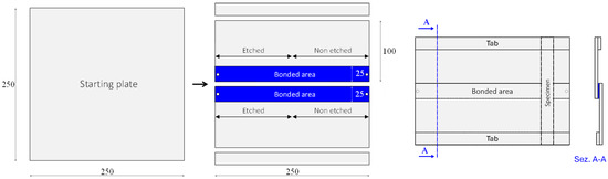
Figure 1.
Steps to obtain the single-lap joint specimens from bonded panels.
3. Quasi-Static and Fatigue Tests
Quasi-static and fatigue tests were performed on single-lap joints produced as previously described.
3.1. Results for MAT1
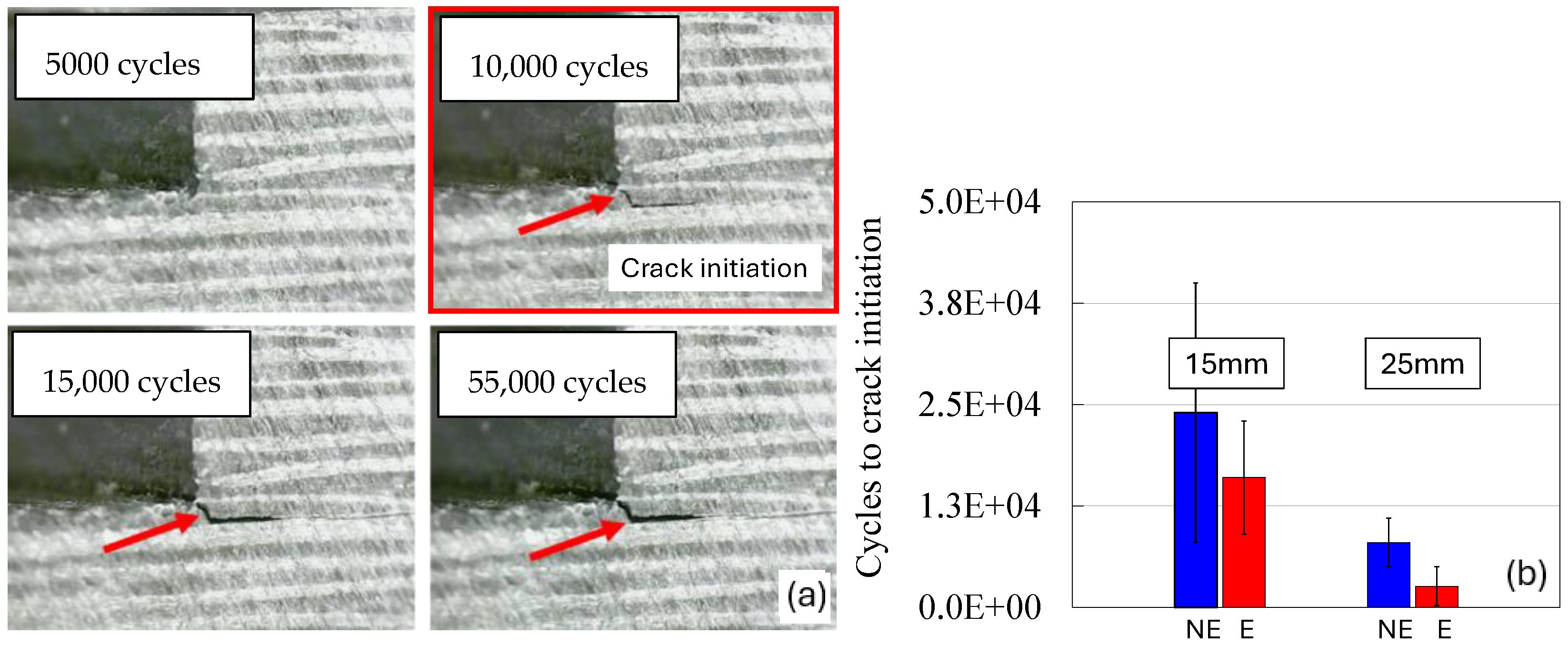
Quasi-static tests were carried out on specimens with a 20 mm width (b) and 15 and 25 mm overlap lengths (w). The average shear stress at failure (τav = F/(w*b)) was calculated, showing a slight increase in static strength for etched specimens with a 15 mm overlap, while results for the 25 mm overlap were comparable (Table 1). Fatigue tests were then conducted with a load ratio of R = 0, a frequency of 5 Hz, at 40% and 30% of the ultimate average shear stress. Crack initiation and propagation were monitored using a direct visual inspection of the polished edges via on-board cameras (Figure 2a). No positive effect of etching on fatigue resistance to crack initiation was observed (Figure 2b), as well as for the total life to failure. Both etched (E) and non-etched (NE) specimens exhibited delamination of the adherend, suggesting that surface treatment had no impact since the crack propagates inside the laminates.

Table 1.
Results from the quasi-static and fatigue tests on MAT1.

Figure 2.
(a) Example of crack monitoring. (b) Fatigue resistance to crack initiation at 40% of the static failure load.
3.2. Results for MAT2
Same as for MAT1, quasi-static and fatigue tests on MAT2 showed no significant effect of etching on static and fatigue strength (Table 2), with cohesive failure observed in both etched and non-etched specimens. The fractured surfaces revealed a cohesive failure for all the configurations, justifying the insensitivity to the surface treatment. Micro-CT analyses, conducted after the fatigue tests, revealed that cracks propagated into the first layer of adherends in both etched and non-etched samples (Figure 3).
Table 2.
Results from the quasi-static and fatigue tests on MAT2.
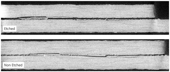
Figure 3.
Micro-CT analyses of MAT2 specimens after the fatigue tests; comparison between the etched and the non-etched configurations.
4. Modelling and Validation
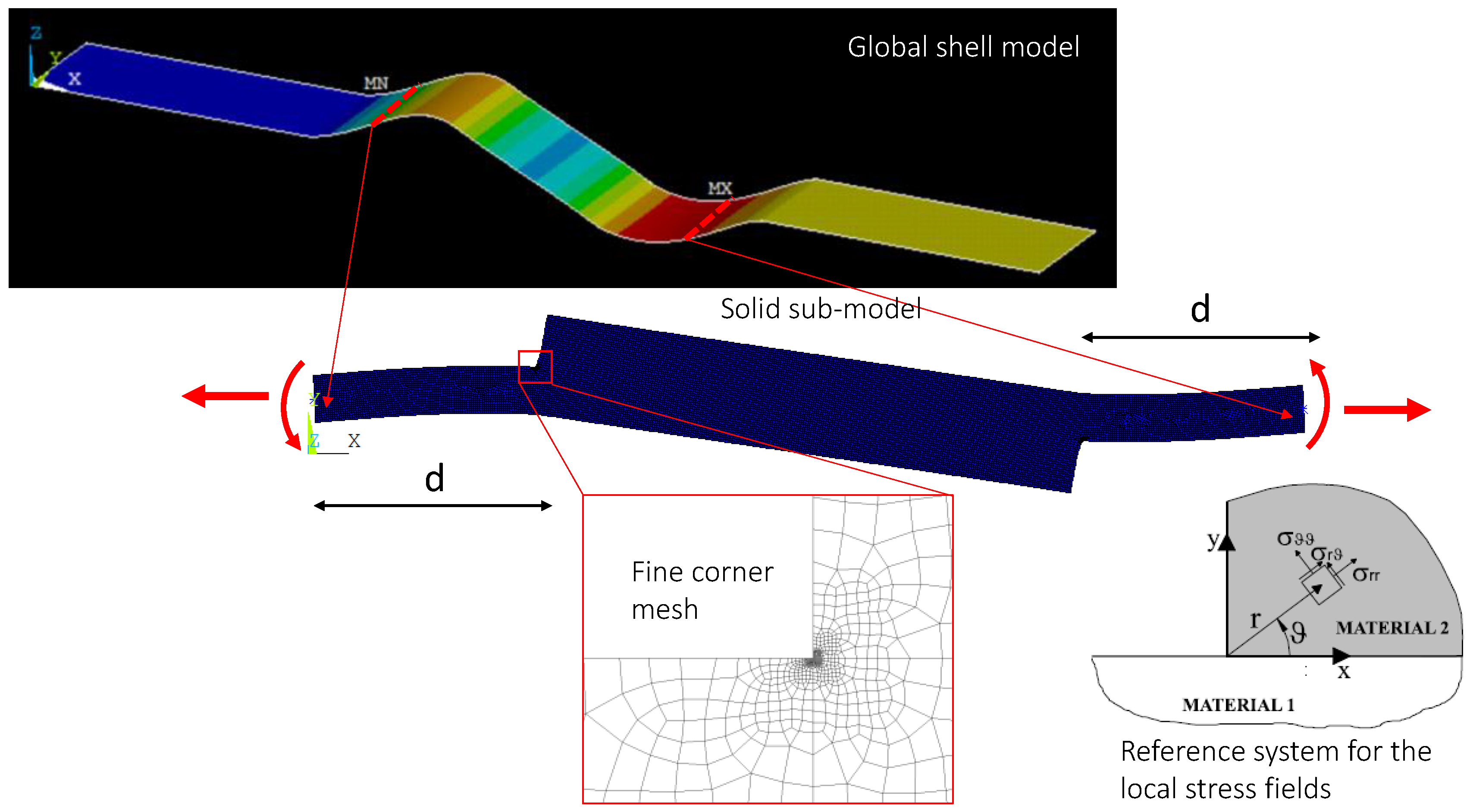
As highlighted in the previous section, the behaviour of bonded joints involves two phases: crack initiation at bondline corners and crack propagation leading to joint failure. Under quasi-static loads, these phases are difficult to distinguish due to the rapid propagation after crack initiation. In contrast, under fatigue loads, crack propagation is stable, with failure occurring when the crack reaches a critical length. Predicting crack initiation is crucial to deal with both static failure and fatigue behaviour assessments. Since the cracks form at corners where geometrical and material singularities create unbounded stresses, the model must be able to consider the singular nature of local stress fields. At the same time, the approach must be applicable to complex structures.
To address these challenges, a two-step simulation strategy was developed (Figure 4). First, a global analysis is carried out using shell elements for the full joint, with the adhesive included as a layer in the shell lay-up definition. Then, a local analysis of the bond area ± a distance, d, from the corners is performed using 2D solid elements in generalized plane strain, with fine meshing around the corners. Displacements and rotations from the global model are applied as boundary conditions to the local model, leveraging the Saint-Venant principle. This approach ensures efficient global modelling while allowing for accurate local stress evaluation, making it suitable for industrial applications.
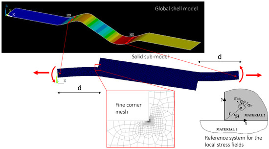
Figure 4.
Schematization of the two-step procedure.
The local 2D FE analysis is used to describe the local stress fields near the corners using Generalized Stress Intensity Factors (GSIFs). As the lap joint can be represented as a plane problem, the stress fields in the neighbourhood of the corner can be written, in the polar coordinates defined in Figure 4, as a sum of infinite terms [3]:
fijk(θ) are angular functions, different for each stress component σij, whereas λk are the eigenvalues of the problem that depend on the material elastic properties and the corner angle. Hk may be defined as the Generalized Stress Intensity Factor (GSIF) associated with the k-th term of the summation. The first eigen value, λ0 = s from now on, is typically within the interval −0.5 ÷ 0, thus giving rise to a singular stress field. The following terms have higher and higher eigenvalues so that the stress distribution in the vicinity of the corner tip is governed by the first term only. Near the corner tip, the stress distribution can thus be written as follows [4]:
An analytical approach for determining the eigenvalues of the problem is reported in Ref. [5]. Being interested in the evaluation of the interface stress intensity, and without a loss of generality, it can be assumed that fθθ0(0) = 1, so that the GSIF can be calculated as
starting from the nodal stress results of linear elastic FE analyses with a very fine mesh in the corner tip region. An approach was developed by Quaresimin and Ricotta [6], according to which the crack initiation must be predicted based on the local parameter H0, which quantifies the intensity of the local stress fields at the bi-material corner.
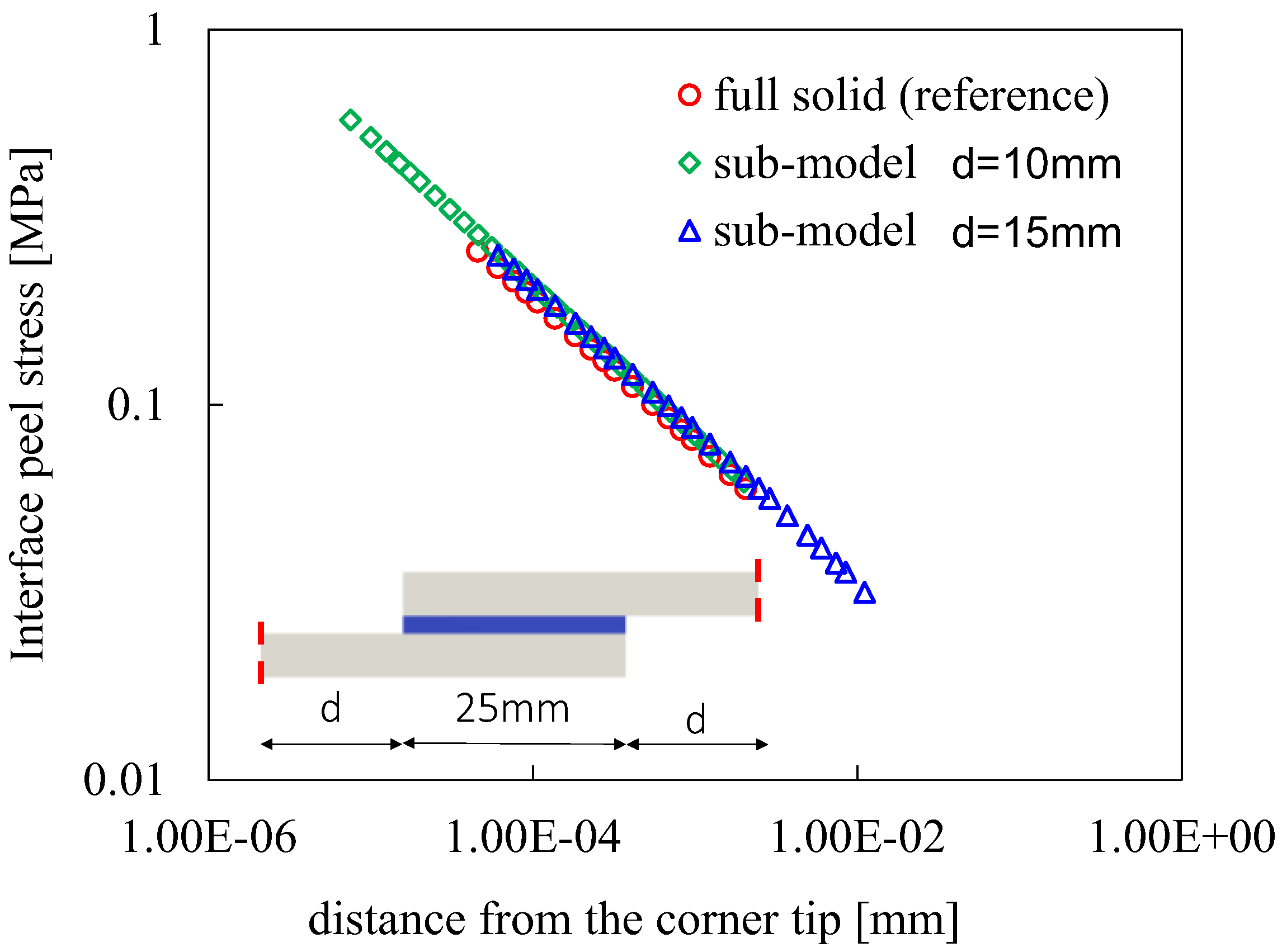
Before the application, the two-step method was numerically validated referring to a single-lap specimen with a 25 mm overlap, comparing the local stress fields with those from a full solid model. The results, shown in Figure 5, demonstrated excellent agreement, confirming the method’s accuracy in calculating the GSIFs.
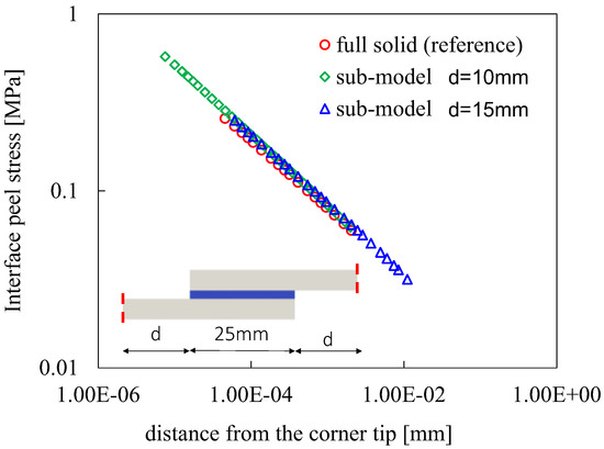
Figure 5.
Numerical validation of the 2-step model.
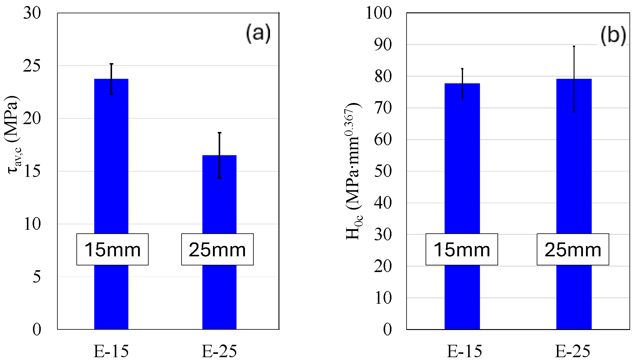
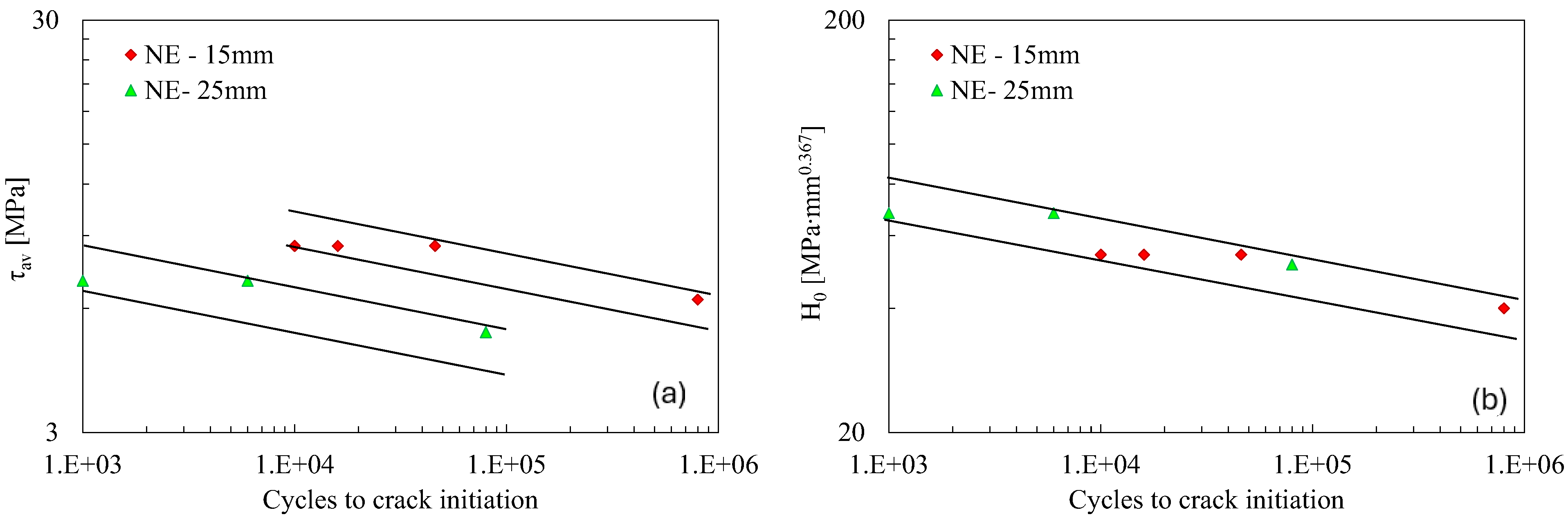
Further validation was performed on MAT1 specimens. The tests showed that specimens with 15 mm and 25 mm overlap lengths fail at different average shear stress values, indicating that τav is an unreliable predictor of joint failure (Figure 6a). Instead, the H0 parameter, derived through geometrically non-linear analyses and the 2-step strategy, provided consistent values at failure (H0c) for both overlap lengths (Figure 6b), suggesting that H0 is a more effective predictor of failure. The model was further validated under fatigue loading conditions (Figure 7), showing that while the average shear stress data for the 25 mm overlap did not align with the 15 mm overlap data, the H0 parameter brought both datasets within the same scatter band. This demonstrates the model’s robustness in predicting crack initiation across different geometries, making it a valuable tool for designing bonded connections.

Figure 6.
Static failure of etched specimens with 15 and 25 mm overlap (MAT1) in terms of average shear stress (a) and H0 parameter (b).
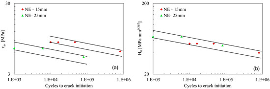
Figure 7.
Fatigue resistance to crack initiation of non-etched specimens with 15 and 25 mm overlap (MAT1) in terms of average shear stress (a) and H0 parameter (b).
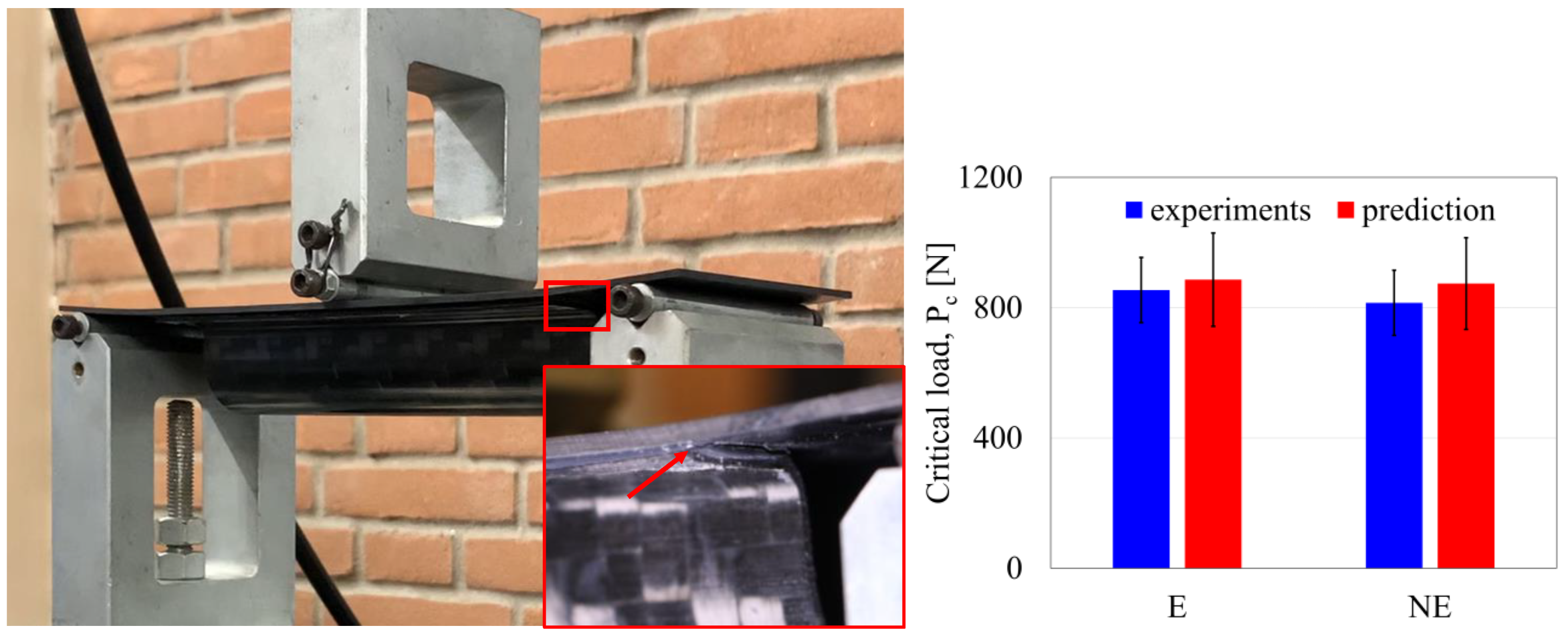
Additional quasi-static tests on etched and non-etched prototypes using three-point bending confirmed the model’s accuracy in predicting the critical load for crack initiation (Figure 8). To predict failure, the H0c values obtained from single-lap joint tests were used together with the 2-step procedure for the H0 calculation, with results closely matching the experimental data.
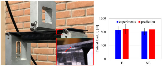
Figure 8.
Setup of the three-point bending test with a magnification of the crack formation, together with the comparison between predicted and measured critical loads for crack initiation.
Overall, the proposed model and stress calculation strategy proved effective in predicting both static strength and fatigue crack initiation, particularly for bonded joints involving high-performance brittle adhesives like MAT1.
5. Health Monitoring Systems
This section addresses the development of a scalable methodology for the structural health monitoring (SHM) of composite-bonded joints, with a focus on thermographic techniques to enhance in-service safety and reliability. According to the literature, both active and passive thermographic techniques can be considered for SHM purposes, particularly Pulsed Thermography (PT), Step Heating Thermography (SHT), Lock-In Thermography (LI), and Thermoelastic Stress Analysis (TSA) [7,8,9,10]. PT, SHT, and LI techniques, while effective in quantifying damaged areas and offering interesting applications for both composite and metal joints, presented some challenges for the in-service SHM of dynamically loaded components due to their reliance on external heat sources.
TSA, although it does not require external heat sources and the ability to detect subsurface damage, faced challenges such as the high cost and size of cooled infrared (IR) sensors required for accurate measurements.
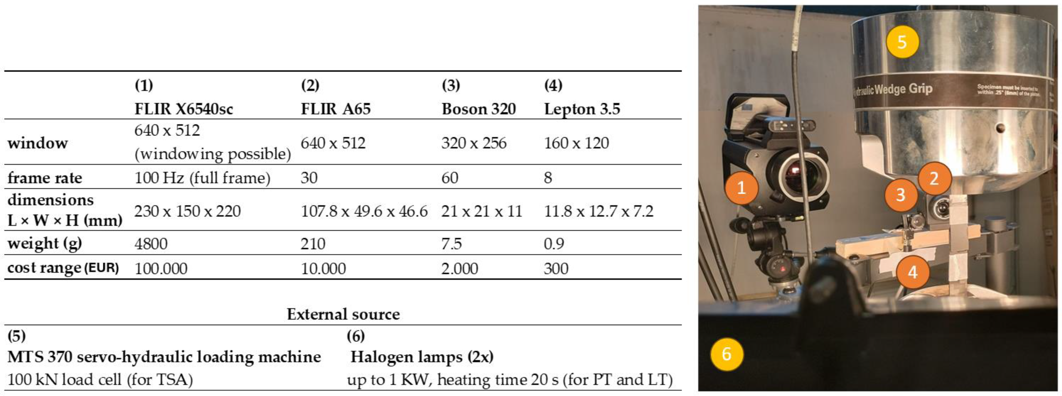
To address these limitations, the present work explored the use of lower-cost, uncooled microbolometer detectors, such as LEPTON and BOSON FLIR cameras, to develop a more feasible SHM system. To demonstrate the first feasibility in terms of resources and procedures for data analysis, experimental tests were conducted on single-lap bonded joints (MAT1) with both of the overlap lengths (15 and 25 mm). The experimental setup (Figure 9) integrated active thermographic techniques and TSA, with a servo-hydraulic loading system used to apply fatigue loads (same parameters as in Section 3). Data acquisition was performed using various infrared cameras with different technical specifications and costs to assess the suitability of various sensors for structural health monitoring applications. The selected cameras varied in resolution, frame rate, and spectral range, offering a range of detection capabilities, as reported in Figure 9.

Figure 9.
Experimental setup for thermographic and fatigue tests with technical and cost specifications.
TSA analyses were performed by processing thermographic sequences and generating thermoelastic maps, which allowed for the localization of damage within the bonded area. Damage assessment was performed by subtracting reference maps (acquired at ~0 cycles) from subsequent thermographic data, which enhanced the contrast between bonded and debonded regions.
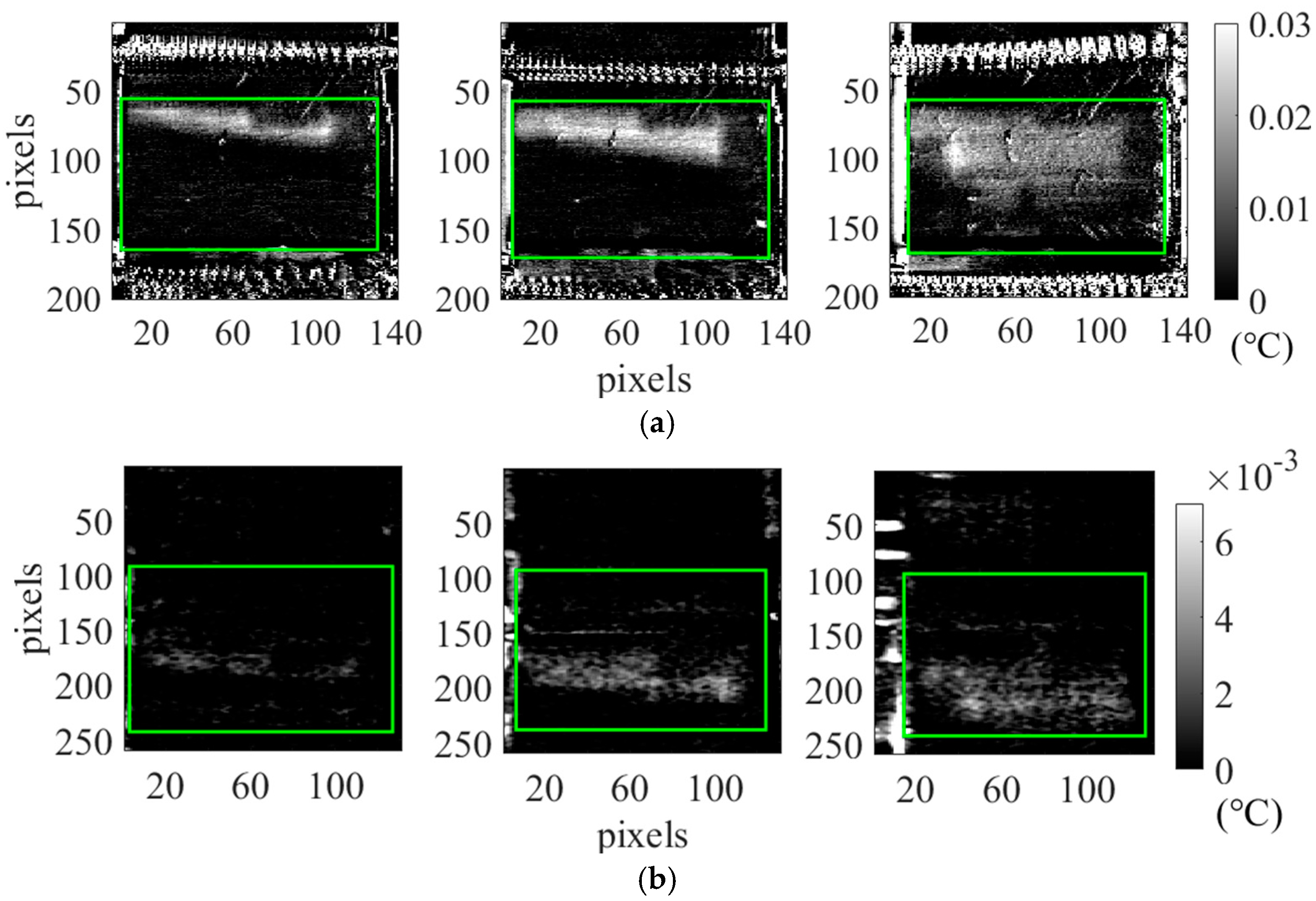
Figure 10 demonstrates the reference TSA results for a non-etched specimen (MAT1) at different fatigue cycle stages (2000, 60,000, and 119,000 cycles). These maps show the increasing extent of debonded areas, as indicated by the growing TSA signal. The results obtained in both cases demonstrated that the TSA signal is extremely low; in fact, the amplitude signal is around 0.03 °C in the case of the cooled IR sensor (Figure 10a), highlighting the challenges for SHM applications, especially for uncooled sensors (Figure 10b).
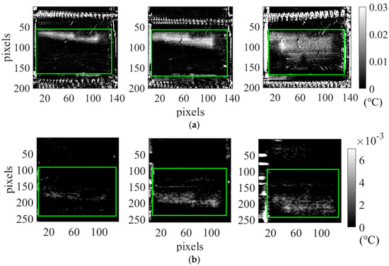
Figure 10.
TSA results showing debonded areas at different cycle stages (2000, 60,000, and 119,000 cycles) using FLIR X6540sc (a) and FLIR A65 (b) cameras, after the subtraction of the first reference map at ~0 cycles; green boxes highlight debonded areas.
Binarization techniques and image/data subtraction, with respect to the first displacement level, were applied to identify the damaged areas more clearly, revealing a consistent growth of the debonded regions as the number of cycles increased.
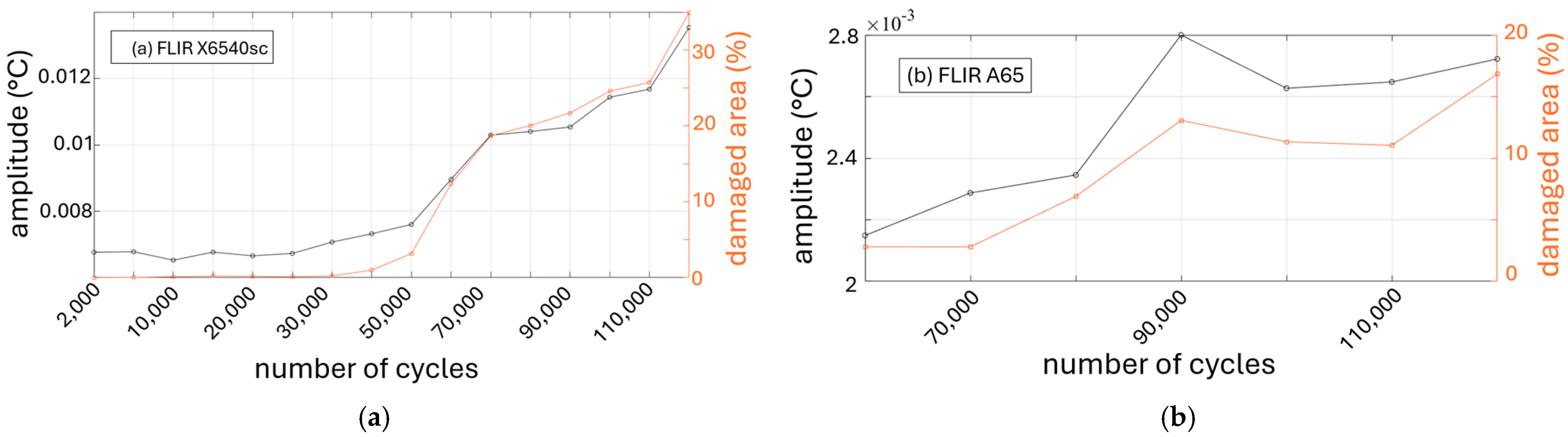
A quantitative analysis (Figure 11) of the debonded area as a function of the number of cycles was performed, showing that significant damage began to occur after approximately 30,000 cycles. This was consistent with the results from both high-cost cooled and lower-cost IR cameras, with the latter showing comparable accuracy in detecting damage despite increased signal noise.
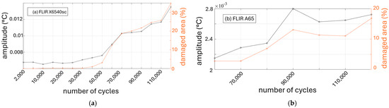
Figure 11.
Quantitative analysis of debonded area growth as a function of the number of cycles: (a) cooled camera FLIR X6540sc; (b) uncooled camera FLIR A65.
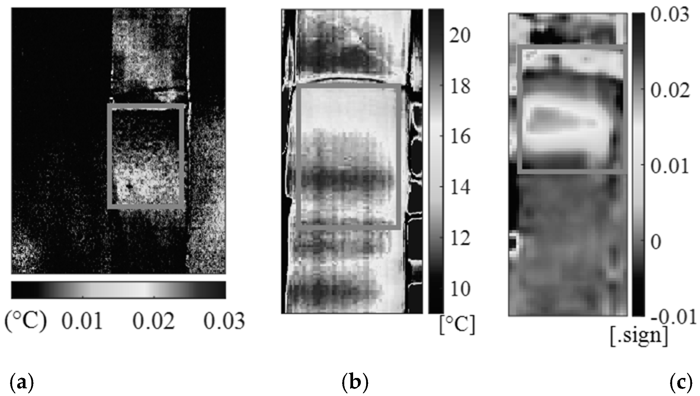
This study also explored the potential of SHT, using halogen lamps as external excitation sources, which yielded results consistent with TSA in terms of detecting debonded areas, as qualitatively shown in Figure 12. The SHT data were acquired offline, stopping the loading machine after 30,000 cycles. The low-cost, compact IR sensors showed promising results, after the application of suitable post-processing algorithms to the acquired raw thermal data, making IR-based SHM strategies feasible for real-world applications. Further research will focus on automating real-time data processing and integrating these techniques into industrial SHM systems, considering an approach based on the use of TSA.
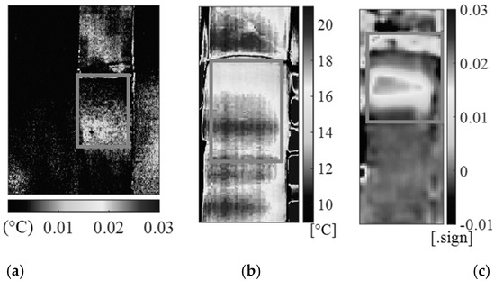
Figure 12.
Comparison between TSA and stepped thermography: (a) TSA results with A65 camera, (b) BOSON camera, SHT amplitude map (Fast Fourier Transform—FFT—considering one cycle), (c) LEPTON camera, SHT 2nd Principal Component (one complete cycle of excitation analyzed by means of Principal Component Analysis—PCA).
6. Conclusions
In this project, research was carried out with the following three objectives:
- (1)
- Increasing the technology readiness level (TRL) of previously developed lab-scale solutions for the chemical etching of composite-bonded joints, with the aim of enhancing bond strength and preventing the negative effects of contamination.
- (2)
- Developing a tool for the efficient application of a local model in industrial design workflows, aimed at assessing the static and fatigue strength of composite-bonded joints.
- (3)
- Defining strategies for the structural health monitoring (SHM) of composite-bonded joints, suitable for in-service applications on real components.
The scaling process was successfully implemented in relation to the three objectives mentioned, leading to the following conclusions:
- ○
- Although preliminary tests showed an increase in joint strength following acid etching, the results from the scaled process did not reveal significant improvements. This is likely due to the higher overall quality of the bonding process, which resulted in failure primarily occurring within the adhesive or the adherends. Nevertheless, the etching treatment effectively eliminates potential surface contamination, thereby reducing the risk of weak bonds.
- ○
- The two-stage approach for calculating local stress fields proved to be highly accurate. The entire methodology, comprising both the model and the calculation approach, was successfully validated under both static and fatigue loading conditions. This represents a robust tool for more reliable bonded joint design, making it suitable for integration into industrial design workflows.
- ○
- IR-based SHM methods demonstrated reliability, even when using sensors with lower cost, size, and weight compared to lab-scale equipment such as cooled cameras. This marks an important step toward integrating these SHM techniques into real-world service conditions, enhancing the safety and reliability of composite-bonded structures.
Author Contributions
Conceptualization: M.Q., P.A.C., M.F., M.D.A., A.M., S.G.A., M.B. and U.G.; methodology: A.B., E.D., D.P., U.G. and P.A.C.; validation: F.L., P.A.C. and M.M.; formal analysis, P.A.C., M.M. and E.D.; investigation: F.L., E.D., D.P. and K.P.; data curation: F.L., M.M. and E.D.; writing—original draft preparation, F.L. and P.A.C.; writing—review and editing: E.D., D.P., M.M. and M.F.; supervision, M.Q., U.G. and M.D.A.; funding acquisition, M.Q. All authors have read and agreed to the published version of the manuscript.
Funding
The work was financed by the European Union—NextGenerationEU (National Sustainable Mobility Center CN00000023, Italian Ministry of University and Research Decree n. 1033—17/06/2022, Spoke 11—Innovative Materials & Lightweighting). The opinions expressed are those of the authors only and should not be considered as representative of the European Union or the European Commission’s official position. Neither the European Union nor the European Commission can be held responsible for them.
Informed Consent Statement
Informed consent was obtained from all subjects involved in the study.
Data Availability Statement
Data will be made available on request to the authors.
Conflicts of Interest
Author Silvia Giovanna Avataneo and Matteo Basso were employed by the company Stellantis S.p.A. Author Andrea Merulla was employed by the company Ferrari S.p.A. The remaining authors de-clare that the research was conducted in the absence of any commercial or financial relationships that could be construed as a potential conflict of interest.
References
- De La Pierre, S.; Giglia, V.; Sangermano, M.; Cornillon, L.; Damiano, O.; Ferraris, M. Etching of Carbon Fiber-Reinforced Plastics to Increase Their Joint Strength. J. Mater. Eng. Perform. 2020, 29, 242–250. [Google Scholar] [CrossRef]
- De La Pierre Des Ambrois, S.; Ferraris, M. Processo di Attacco Acido Della Superficie di Compositi a Matrice Polimerica Senza Interrompere la Continuità Delle Fibre, al Fine di Migliorare la Resistenza Meccanica di una Giunzione. Patent N. 102019000022026, 25 November 2019. [Google Scholar]
- Bogy, D.B. Edge-bonded dissimilar orthogonal elastic wedges undernormal and shear loading. J. Appl. Mech. 1968, 35, 460–466. [Google Scholar] [CrossRef]
- Lazzarin, P.; Quaresimin, M.; Ferro, P. A two-term stress function approach to evaluate stress distributions in bonded joints of different geometries. J. Strain Anal. Eng. Des. 2002, 37, 385–398. [Google Scholar] [CrossRef]
- Zappalorto, M.; Carraro, P.; Quaresimin, M. Analytical Solution For The Three-Dimensional Stress Fields In Anisotropic Composite Bimaterial Corners. Compos. Struct. 2015, 122, 127–138. [Google Scholar] [CrossRef]
- Quaresimin, M.; Ricotta, M. Life prediction of bonded joints in composite materials. Int. J. Fatigue 2006, 28, 1166–1176. [Google Scholar] [CrossRef]
- Palumbo, D.; De Finis, R.; Galietti, U. Thermoelastic stress analysis as a method for the quantitative non-destructive evaluation of bonded CFRP T-joints. NDT E Int. 2021, 124, 102526. [Google Scholar] [CrossRef]
- D’Accardi, E.; De Finis, R.; Dell’Avvocato, G.; Masciopinto, G.; Palumbo, D.; Galietti, U. Conduction thermography for non-destructive assessment of fatigue cracks in metallic materials. Infrared Phys. Technol. 2024, 140, 105394. [Google Scholar] [CrossRef]
- Palumbo, D.; Tamborrino, R.; Galietti, U.; Aversa, P.; Tatì, A.; Luprano, V.A.M. Ultrasonic analysis and lock-in thermography for debonding evaluation of composite adhesive joints. NDT E Int. 2016, 78, 1–9. [Google Scholar] [CrossRef]
- De Finis, R.; Palumbo, D.; Galietti, U. A new procedure for fatigue life prediction of CFRP relying on the first amplitude harmonic of the temperature signal. Int. J. Fatigue 2023, 168, 107370. [Google Scholar] [CrossRef]

Disclaimer/Publisher’s Note: The statements, opinions and data contained in all publications are solely those of the individual author(s) and contributor(s) and not of MDPI and/or the editor(s). MDPI and/or the editor(s) disclaim responsibility for any injury to people or property resulting from any ideas, methods, instructions or products referred to in the content. |
© 2025 by the authors. Licensee MDPI, Basel, Switzerland. This article is an open access article distributed under the terms and conditions of the Creative Commons Attribution (CC BY) license (https://creativecommons.org/licenses/by/4.0/).