Proceeding Paper

Comparative Review of Rotary Friction Welding Between Aluminium and Copper Alloys for Enhanced Joint Strength †

1
Department of Mechanical Engineering, Sebelas Maret University, Ir Sutami No 36 A, Jebres, Surakarta 57126, Indonesia
2
Research Center for Transportation Technology, National Building Number 720 KST B.J. Habibie Serpong, South Tangerang 15314, Indonesia
*
Author to whom correspondence should be addressed.
Presented at the 8th Mechanical Engineering, Science and Technology International Conference, Padang Besar, Perlis, Malaysia, 11–12 December 2024.
Eng. Proc. 2025, 84(1), 92; https://doi.org/10.3390/engproc2025084092
Published: 6 May 2025

Abstract

This study evaluates and compares the effectiveness of friction stir welding on aluminium and copper alloys with the aim of improving the strength of the resulting joints. The rotary friction stir welding method was chosen for its ability to produce high-quality joints with minimal deformation. This study explores various welding parameters, such as rotating speed, welding speed, and tool design, and their impact on the mechanical properties of the joint, including tensile strength, hardness, and microstructure of the weld region. The findings show that the optimum parameters for aluminium and copper alloys differ significantly: the tensile strength of aluminium is around 240 MPa, while copper joints require careful adjustment to avoid defects, reaching around 220 MPa. Aluminium showed improved joint strength with higher rotating speed and welding speed parameters, while copper required more precise parameter adjustments to prevent cracking and other defects. The results of this study provide practical guidance for selecting appropriate rotary friction welding parameters to optimize joint strength in aluminium and copper alloys, which can enhance the application of these materials in industry.

1. Introduction

Rotary friction welding (RFW) is a solid-state joining process that has gained significant attention in the field of material joining due to its ability to produce high-strength joints between dissimilar materials [1,2]. This review analyzes the rotary friction welding process between aluminium and copper alloys, focusing on factors affecting joint strength and performance enhancement that involve heat generation and pressure application [3,4]. The heat generated at the interface is lower than the base metals’ melting temperatures, enabling solid-state welding without the use of additional heat sources [5]. This process is particularly advantageous for joining dissimilar materials, such as aluminium and copper alloys, which have vastly different physical and metallurgical properties [6,7].
The important variables in rotary friction welding that govern the quality and strength of the joint are the axial pressure, rotational speed, and welding time [8]. The parameters at the interface impact heat generation, microstructural evolution, and the formation of intermetallic compounds, necessitating careful optimization for a robust joint. [9]. Previous studies have investigated the effects of these process parameters on the joint strength and microstructural characteristics of aluminium–copper friction welds [10]. The study suggests that increased rotational speed and axial pressure can enhance joint strength by stimulating the production of a thin, continuous layer of intermetallic compounds [11]. To overcome these problems, researchers have investigated numerous ways of controlling microstructural evolution and increasing joint strength [12]. Utilizing interlayer materials like copper or aluminum as a diffusion barrier and optimizing welding parameters can prevent thick, brittle intermetallic compounds [8,10]. The mechanical properties, corrosion resistance, and electrical conductivity of aluminium–copper friction welds are crucial factors, especially in automotive and aerospace applications [13,14]. The presence of intermetallic compounds at the interface can impact these properties, and further research is needed to understand the relationship between the microstructural characteristics and the functional performance of the joints [15]. This study evaluates and compares the effectiveness of friction stir welding on aluminium and copper alloys with the aim of improving the strength of the resulting joints.
A.
Background and Significance
Rotary friction welding (RFW) is a promising technique for joining dissimilar metals like aluminium and copper, crucial in industrial applications due to their complementary properties [16,17]. However, the significant differences in physical and mechanical properties between these metals pose considerable challenges for conventional welding methods. The schematic of RFW and the process phases of CDFW are shown in Figure 1.
Recent advancements in RFW have shown potential in overcoming these challenges [19,20] demonstrated that RFW can produce Al-Cu joints with up to 85% of the strength of the weaker base metal, surpassing the performance of traditional fusion welding techniques. The improvement is attributed to the solid-state nature of the process, which minimizes the formation of brittle intermetallic compounds that typically weaken the joint interface. The chemical compositions of copper and characters of copper are shown in Table 1 and Table 2.
The significance of this research lies in its potential to revolutionize manufacturing processes across multiple sectors. In the automotive industry, refs. [22,23,24] reported that the use of Al-Cu friction-welded components could lead to a 15% reduction in vehicle weight, contributing to improved fuel efficiency and reduced emissions. Moreover, the environmental implications of RFW are substantial. A life cycle assessment conducted by [25,26] showed that RFW of Al-Cu components can reduce energy consumption by up to 30% compared to traditional welding methods, aligning with global sustainability goals, but challenges remain in optimizing the process. Refs. [1,26] identified the need for a comprehensive understanding of the relationship between process parameters, microstructural evolution, and joint properties to achieve consistent, high-strength welds across various applications. The chemical compositions of aluminium AA is shown in Table 3.
This review critically evaluates recent advancements in RFW of Al-Cu alloys, focusing on joint strength enhancement strategies, optimal process parameters, microstructural control, and performance characteristics. [27,28] identified critical factors influencing weld quality and strength. This study evaluates recent developments in process parameters optimization for relative welding (RFW) of Al-Cu alloys, focusing on factors influencing weld quality and strength [25,29,30]. It also assesses microstructural evolution and intermetallic compound formation during RFW [31,32]. The study compares Al-Cu friction welds with other welding techniques [18,32], analyzes tool design and process modifications for joint strength enhancement, and examines surface preparation and interlayer usage.
B.
Scope of the Review
This review focuses on the recent advancements in rotary friction welding (RFW) between aluminium and copper alloys, with an emphasis on enhancing joint strength. The scope encompasses an analysis of process parameters and their optimization for Al-Cu RFW, as well as an evaluation of microstructural characteristics and their influence on joint properties. It also includes an assessment of mechanical properties, including tensile strength, hardness, and fatigue resistance.

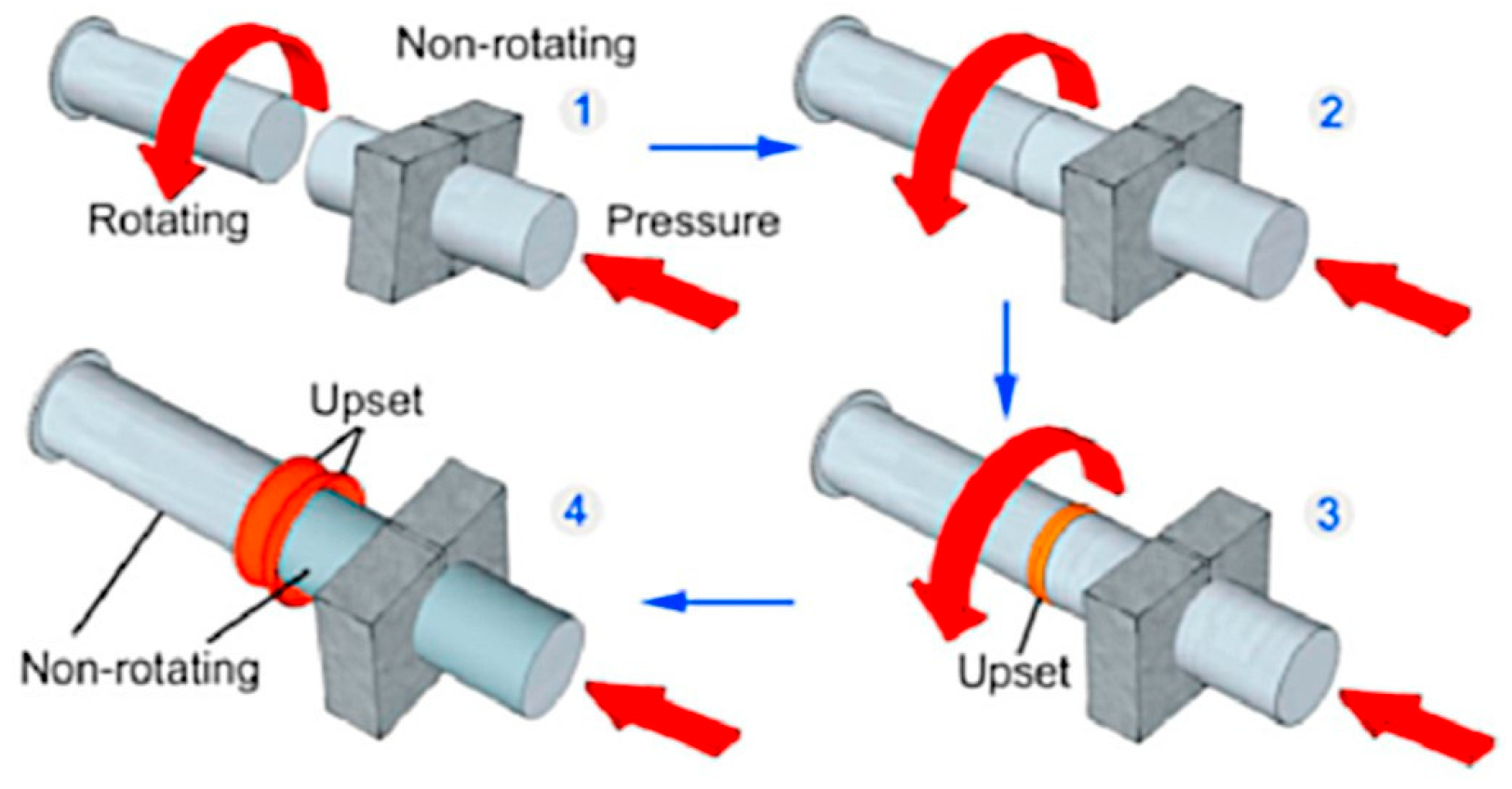
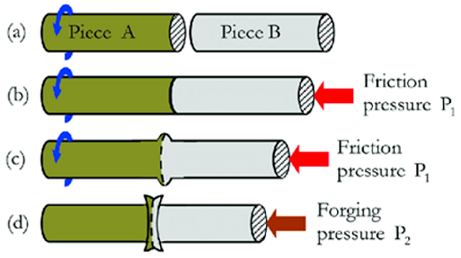
2. Fundamentals of Rotary Friction Welding

RFW, a solid-state joining process, simplifies and reduces contamination risk, while advanced control technologies improve joint strength and reliability in aluminum and copper joints [21,33]. Selecting materials with high thermal conductivity enhances the welding process by reducing thermal damage. Microstructural analysis helps optimize process parameters. Rotary friction welding (RFW) offers strong, reliable joints for joining aluminum and copper alloys [21,34]. Rotary friction welding is a crucial technique in industries like automotive, aerospace, and manufacturing for joining challenging materials by utilizing frictional heat and pressure to create strong metallurgical bonds [18,28]. Rotary friction welding schemes are shown in Figure 2.
Figure 2 show Rotary friction welding (RFW) is a solid-state welding technique in which heat is generated through mechanical friction between rotating component surfaces pressing against each other. (a-b) In this stage, one of the workpieces rotates while the other is stationary. When the two are pressed together with a certain pressure, the friction at the contact surfaces generates significant heat. This heat causes the material in the contact zone to become soft and plasticized (the “upset” process), which is visible as deformation or shortening of the specimen. (c-d) Once enough heat has been generated, rotation is stopped (cessation of rotation) and a higher axial pressure is applied (forging pressure). This stage consolidates the joint by compacting the plasticized material, creating a strong metallurgical bond across the joint surface. The rotary friction welding process is an energy efficient and environmentally friendly welding method as it does not require filler metals or shielding gases like conventional fusion welding methods [35].
The welding process relies on factors like friction pressure, upset pressure, friction time, spindle speed, and upset time. Proper material selection, surface preparation, and process control improve heat transfer and reduce thermal damage risk [36]. Surface preparation and advanced process control techniques, like Design of Experiments and Response Surface Methodology, enhance joint strength and dependability by eliminating pollutants [37,38]. Advancements in process control, machine learning, and material selection have improved welding conditions, joint strength, efficiency, and reliability while eliminating material degradation risks in aluminium and copper alloys [33]. RFW offers minimal distortion to materials, maintaining joint structural integrity and eliminating the need for filler metal; this simplifies the process and reduces contamination risks [18,39]. RFW is a cost-effective, environmentally friendly welding process that reduces waste and improves electrical conductivity in copper and aluminium joint applications but may be restricted in certain industries [40].

3. Material Characteristics

Properties of Aluminium and Its Alloys

Aluminium alloys are widely used in various industries due to their unique properties [38]. The comparative review of rotary friction welding between aluminium and copper alloys focuses on key properties of aluminium alloys for enhanced joint strength. Tensile strength: Aluminium alloys have a high tensile strength, which is crucial for structural applications. Figure 3 presents the dimensions and shape of the Al–Mg–Si–Cu sample prepared for the uniaxial tensile test. For example, the tensile strength of AA6063 is approximately 240 MPa [1]; in [21], the tensile shear strength of the joint produced with the addition of Ni effectively improved the Al/Cu weld strength, reaching approximately 60 MPa at 3 at.% Ni [25,41]. The study reveals that MFSC exhibits a 40% increase in tensile strength due to the keyhole effect, resulting in a significant improvement in tensile shear strength [42]. Yield strength: Aluminium alloys exhibit high yield strength, which is essential for maintaining structural integrity. The yield strength of AA6063 is around 180 MPa [3]. The study demonstrates that the tensile properties of FSW specimens increase at cryo-temperatures, with the highest yield strength obtained from the HAZ specimen of 291 MPa [43,44].
Silicon content: Silicon in aluminium alloys improves corrosion resistance and enhances mechanical properties. Silicon content in AA6063 is typically around 0.4–0.8% [21]. According to [45], increasing silicon content in aluminium alloys decreases melting point, increases fluidity, and ultimately increases ultimate tensile strength, impacting chip formation and improving strength and corrosion resistance [21]. According to [46], microstructure significantly influences material properties, with phase distribution and size affecting strength parameters. Al-Cu alloys are refined with copper, while aluminum bronzes offer excellent mechanical properties and corrosion resistance [47]. Copper content: Copper is added to some aluminium alloys to enhance their strength and corrosion resistance. Copper content in AA6063 is typically around 0.15–0.4% [21]. Copper enhances brake pad thermal conductivity, reducing contact temperatures at the pad–disc interface, despite the disc absorbing most of the friction heat, playing a crucial role in braking performance. [48]. Aluminium alloys have high thermal conductivity, which is beneficial for applications where heat dissipation is critical. The thermal conductivity of AA6063 is approximately 180 W/mK [21]. Copper–aluminum (Cu/Al) hybrid pipes have good thermal conductivity and corrosion resistance and are lightweight, making them suitable for use in electric car heat exchangers and home appliances [49]. The addition of 5 wt% Cu to an Al-5Cu-0.5CNT hybrid composite improved its electrical, thermal, and mechanical properties while decreasing electro-thermal conductivity due to agglomeration [50]. Aluminium alloys exhibit exceptional corrosion resistance due to the formation of a thin oxide layer on their surface, which safeguards the underlying metal [51]. Passivation can enhance the corrosion resistance of aluminium alloys, especially in applications requiring exposure to corrosive environments [52]. Aluminium alloys, like AA6063, are extensively utilized in the aerospace industry due to their light weight, high strength-to-weight ratio, and corrosion resistance [51]. Aluminium alloys are increasingly used in the automotive industry for components such as engine blocks, cylinder heads, and suspension components. Their light weight and corrosion resistance make them ideal for these applications [53]. Aluminium alloys are also used in electrical conductors due to their high electrical conductivity. For example, AA6063 is used in electrical connectors and cables due to its good electrical conductivity and corrosion resistance [21].
Advancements in process control, including machine learning algorithms, have improved joint strength and reliability by enabling precise control over welding parameters [21,25]. The changes in rotation speed, friction pressure, and forging pressure during the welding process are depicted in Figure 4, highlighting the transition between different welding stages. Selecting materials with high thermal conductivity can improve welding by facilitating heat transfer and reducing thermal damage risk, including copper [31]. Microstructural analysis offers insights into joint mechanical properties, enabling informed process optimization and the development of new joining techniques [19,31]. The study reveals that increasing rotation speed in Al-Cu alloy FSW leads to finer, equiaxed welded grains, while larger, clustered precipitates develop due to faster plastic deformation and high-temperature exposure [54]. DOE and RSM tools have enabled the optimization of process parameters for improved joint strength and reliability, identifying optimal parameter sets for specific materials and applications [28,55]. Aluminum alloys are ideal for structural and electrical applications due to their strength, corrosion resistance, and thermal conductivity, enhanced by advanced process control and material selection [56,57].
Copper and its alloys are widely used in various industries due to their unique properties [58,59]. Here are some key properties of copper and its alloys, particularly relevant to the topic of a comparative review of rotary friction welding between aluminium and copper alloys for enhanced joint strength [60]. Copper has a high tensile strength, which is crucial for structural applications. For example, the tensile strength of copper is approximately 220 MPa [61,62]. In addition, weld mechanical properties, such as ultimate tensile strength, have been investigated, with the optimum parameters resulting in a strength of 194.5 MPa [63].
Copper, with a yield strength of around 170 MPa, is crucial for maintaining structural integrity [60,61,62,63,64]. Cold working enhances copper’s hardness, making it crucial for wear and deforestation applications. Tapper cylindrical pin tools offer superior mechanical qualities [65,66]. Copper alloys, typically 90–99% copper, are strong, corrosion-resistant, and contain other metals like zinc, tin, and nickel. Their strong thermal conductivity of around 400 W/mK is ideal for efficient heat dissipation [34,67,68]. Copper has a relatively high coefficient of thermal expansion, which can have an impact on performance in applications that need regular heat cycling [34,69]. Copper and its alloys are known for their high corrosion resistance due to thin oxide coatings. Tungsten copper composites, with excellent conductivity and low thermal expansion, are widely used in thermal and electrical applications [70]. This paper explores copper corrosion protection, highlighting its superior electrical conductivity and resistance and how advanced processes, machine learning, and high thermal conductivity materials improve welding conditions and joint strength [71,72,73].
The welding process of dissimilar Al-Cu materials presents significant challenges due to physical and chemical differences, necessitating careful attention for robust, dependent junctions [21,74]. This discrepancy might cause the aluminum to overheat during the welding process, degrading its mechanical qualities [75,76,77]. Intermetallic compounds (IMCs) formed during welding between aluminum and copper can negatively affect joint mechanical properties, hinder welding, and necessitate the removal of oxide layers for strong connection [78,79]. The study examined the compatibility of aluminum and copper in friction stir welding for optimal joint strength, highlighting the potential benefits of ultrasonic vibrations [63,80]. According to [81], the study examined the impact of base metal composition, filler metal composition, and welding heat input on AISI 316 microstructure, HAZ extent, and micro-hardness, emphasizing the need for effective environmental management [49,82]. The use of machine learning techniques in process control has significantly enhanced welding conditions, thereby enhancing joint strength and reliability [83].

4. Results and Discussion

4.1. Analysis of Process Parameters and Their Optimization for Al-Cu RFW

According to [28], the study identified optimal process conditions for dissimilar AA1050/Cu FSSW joints, resulting in a shear failure load of 4.83 kN and vibration signal energy of 533.74 m2s−1 [55]. The duration of welding significantly impacts energy and tensile strength, with longer durations increasing heat input and reducing weld strength due to friction at the weld contact [84]. Figure 5 [27] displays the 2195 aluminum alloy process window predicted by the model using sample data. The pink curved surface in Figure 5 represents all process parameters that correlate to the maximum projected tensile strength (415 MPa), as indicated by the red arrows. The process parameters for the pink surface were a rotational speed of 1650 rpm to 1850 rpm, a welding speed of 100 mm/min to 110 mm/min, and a welding pressure of 2.9 kN to 3 kN [27]. Figure 6 presents the variation of relative tensile strength as a function of average welding energy in Al–Cu welds, highlighting the influence of energy input on joint performance.
According to research by [18], Al-steel joints offer lower costs, weight, and unique qualities, attracting interest in industries like automobiles, aerospace, and marine. However, designing complex systems is challenging due to metallurgy complexity. To reduce intermetallic compounds, surface modification, post-welding, heat input control, and interlayer material utilization can be used. The base plates of AA6061 and AA2014 were produced using FSW, with maximum UTS observed at 1200 rev/min, WS of 100 mm/min and a TTA of 2°. The welded junction’s microstructure was polished and homogeneous, with no defects due to FSW parameters [85]. The variation of UTS, % elongation, and hardness due to the FSW parameters are shown in Figure 7.
Heating pressure significantly impacts the welded joint’s integral strength, while rotational speed significantly affects the interface strength of AISI 1330 and AISI 4340 steels. Ideal RFW parameters include pheating, pforging, 400 rpm, and l = 4 mm, with notch tensile strength ≥ 740 MPa and ultimate tensile strength ≥ 840 MPa [55].

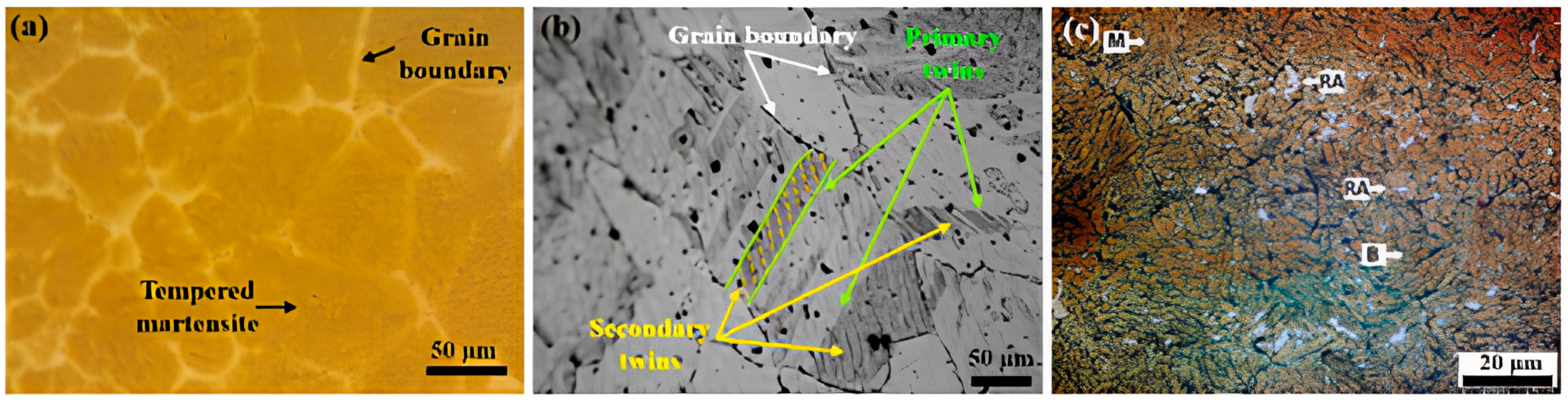
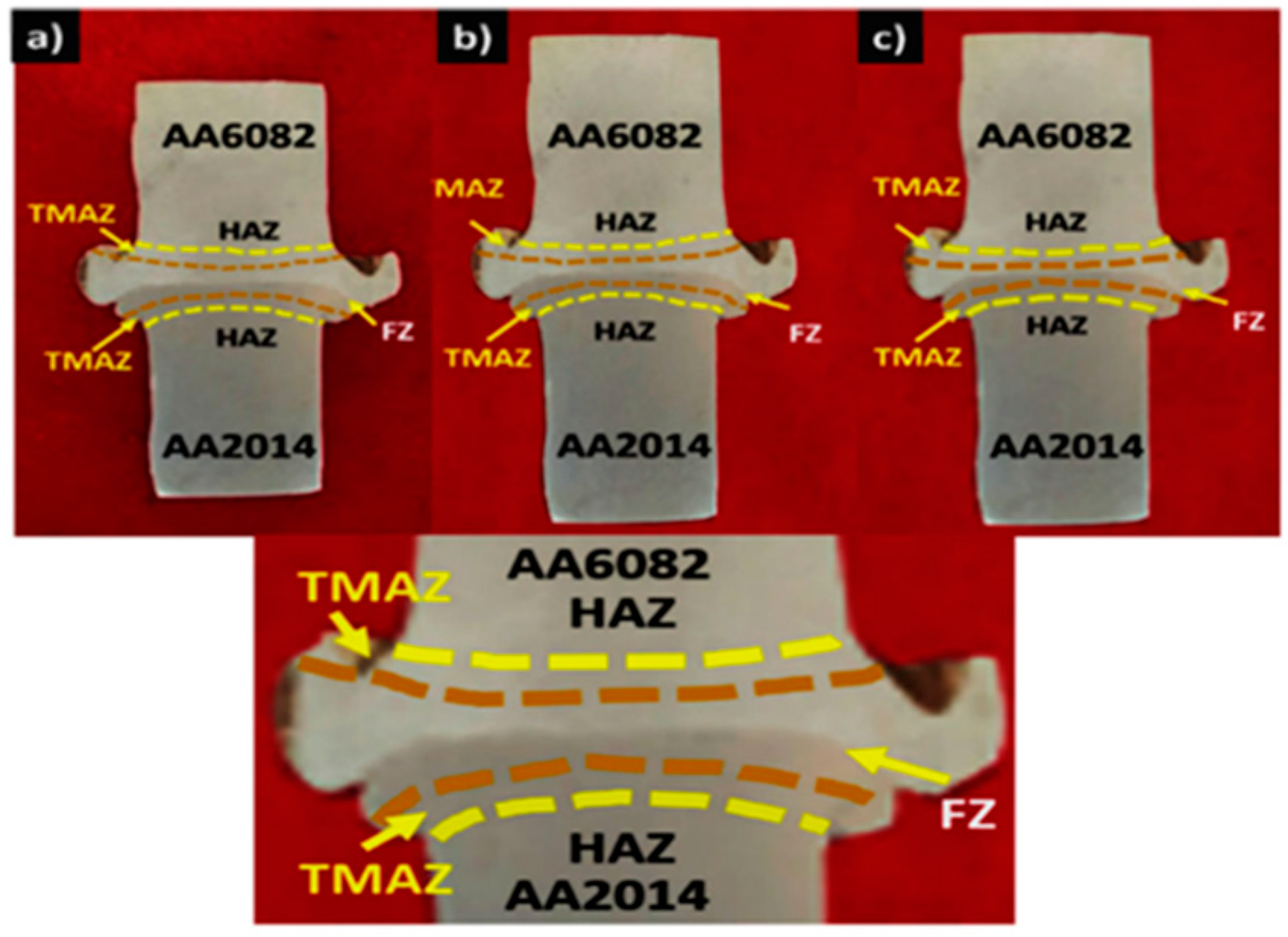
4.2. Evaluation of Microstructural Characteristics and Their Influence on Joint Properties

The study reveals that temperature and deforestation during welding affect precipitate size, dislocation structures, and grain size. High temperature leads to recrystallization, resulting in smaller grain sizes, while plastic deformation can occur from friction pressure and upsetting force [24]. The microstructural characteristics of the base metals used in the welding tests are illustrated in Figure 8, highlighting the tempered martensite in CP steel (Figure 8a), the deformation twins in TWIP steel (Figure 8b), and the multiphasic microstructure in Q&P steel, consisting of martensite (M), bainite (B), and retained austenite (RA) (Figure 8c) [86].
Figure 9 demonstrates welding microstructures of advanced steels, with heat treatment altering CP steel’s dendritic structure, TWIP steel exhibiting mechanical twins, and Q&P steel undergoing two-stepped heat treatment [24]. (a) The microstructure of AA6063 base metal shows equiaxed grains with evenly distributed α-Al phase and Mg2Si precipitates. (b) The weld zone displays a fine grain structure with material flow and plastic deformation at the interface, indicating metallurgical mixing between the two materials. (c) The microstructure of AISI304L base metal shows austenite grains with some twin boundaries typical of austenitic stainless steel [86].
The optical microscope was used to characterize weld zones, revealing good bonding between base metals and weld regions in experimental methods, as shown in Figure 9b [19]. The study measured and plotted the widths of zones in AISI304L and AA6063 using Kroll’s and Glyceregia etchants, revealing thin Al-Si eutectic particles in an Al solid solution matrix [86].
Figure 10 demonstrates the friction-welded specimens were etched using Keller’s reagent, revealing no obvious defects. The S1 specimen’s smaller TMAZ width caused faster fractures and a lack of richer microstructure compared to S6 and S9 [87]. Figure 10a illustrates that the weld joint between AA6082 (at the top) and AA2014 (at the bottom) has a relatively straight interface pattern. There is a clear division of metallurgical zones marked with yellow dotted lines: TMAZ (Thermo-Mechanically Affected Zone)—Heat affected zone and mechanical deformation on both sides of the material. HAZ (Heat Affected Zone)—Heat affected zone without significant plastic deformation on both materials. FZ (Fusion Zone)—The melting/fusion zone in the center where the two materials mix. The weld interface looks relatively straight and may indicate welding parameters with relatively low heat input or high welding speed. Figure 10b describes a welded joint with similar characteristics to sub-figure a, but with a slightly different interface. The same metallurgical zones are also marked (TMAZ, HAZ, FZ). The main difference probably lies in the welding parameters used, which results in a slightly different interface shape and possibly different widths of the HAZ and TMAZ zones. Figure 10c explains that the third welded joint with different interface characteristics again compared to subfigures a and b. The interface pattern and distribution of the TMAZ, HAZ, and FZ zones indicate possibly different welding parameters that result in different heat input or material flow during the welding process.

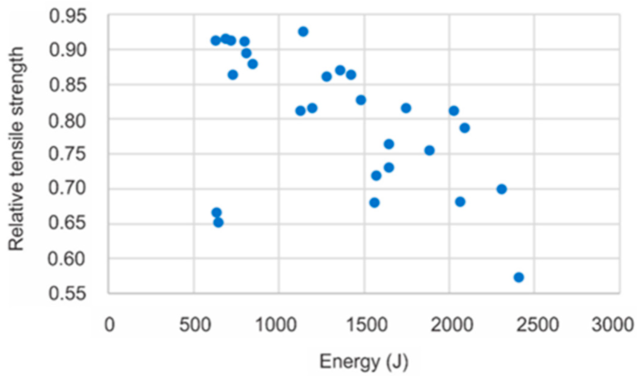
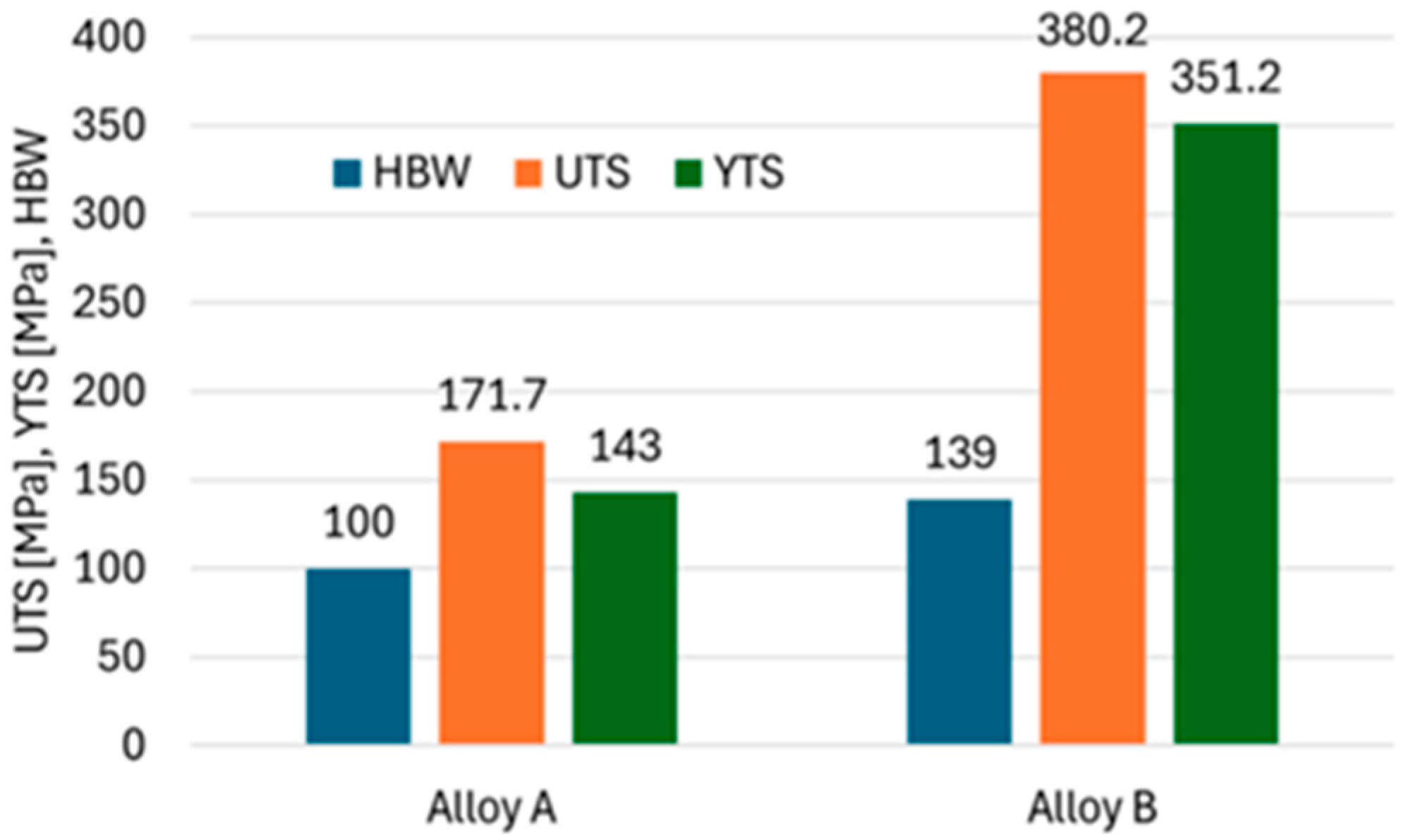
4.3. Assessment of Mechanical Properties, Including Tensile Strength, Hardness, and Fatigue Resistance

Figure 11 demonstrates that Alloy B, with smaller casting faults, is harder and has higher ultimate tensile strength and yield tensile strength. It is twofold stronger and more forceful than Alloy A, with a 145% YTS and nearly double UTS [88]. Alloy B exhibits a YTS of up to 145% and a UTS that is nearly double that of Alloy A. These findings are summarized with the corresponding tolerances in Table 4.
Research in [89] indicates that all weld joints fracture in the AA5083 base metal region, indicating over 100% joint efficiency. Bond formation occurs at speeds above 370 rpm, resulting in high-strength connections.

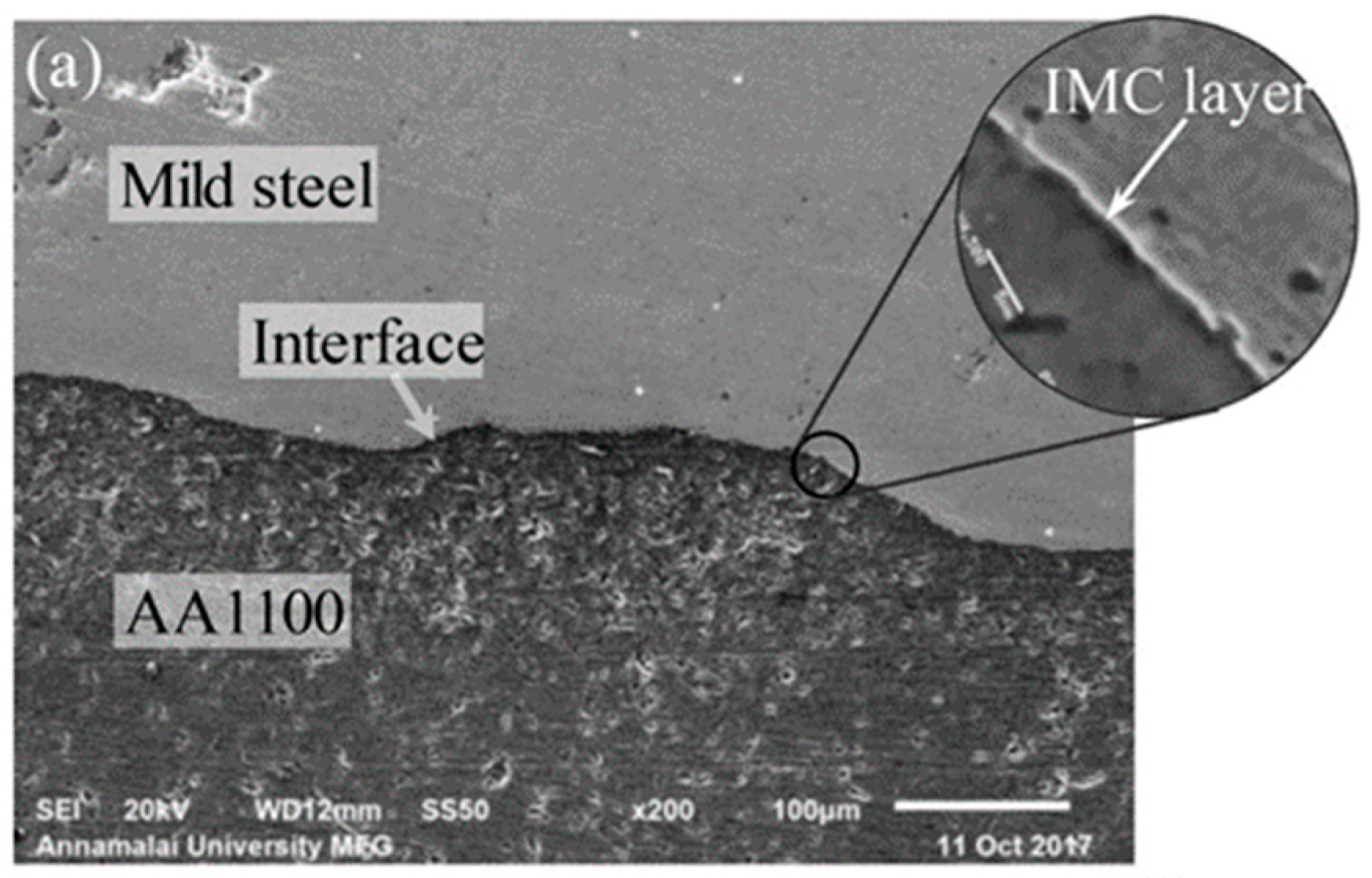
4.4. Testing of Intermetallic Compound Formation and Its Effects on Joint Strength

The microstructural development of Cu/Ga/Cu joints occurs at 150 °C, with large θ grains dividing interlayers into pockets with voids and anisotropy causing gaps at low bonding temperatures [90]. The experiment utilized X-ray fluorescence (XRF) to analyze the chemical compositions of mild steel and aluminum AA1100 cylindrical rods, enabling precise prediction of friction-welded joint hardness and tensile strength [91].
SEM examinations revealed that forging pressure and time impact weld interface microstructure, with low forging pressure resulting in thinner layers at the interface [91]. The study reveals a primary Cu/Al-Cu intermetallic particle size range of 10–20 μm, with sample II having smaller particles. The cold-welding method causes large Cu clusters [92]. As shown in Figure 12, SEM images of the weld interface illustrate these microstructural variations, where sample 7 (Figure 12a) exhibits a relatively smooth interface with minimal defects, sample 11 (Figure 12b) presents a more irregular structure with noticeable voids, and sample 8 (Figure 12c) demonstrates a well-bonded interface with dispersed microvoids, indicating a moderate bonding quality.
Figure 12 show SEM (Scanning Electron Microscope) images showing the weld interface between mild steel and AA1100 aluminum alloy. These are labeled as samples 7, 11, and 8, respectively. Let me analyze what’s visible in each image: Images a:The image shows a cross-section of a weld joint with distinct regions labeled as “Mild steel” (top), “Interface” (middle boundary), and “AA1100” (bottom). There’s a magnified circular inset highlighting an “IMC layer” (Intermetallic Compound layer) at the interface. This layer appears as a distinct thin band between the two materials. Images b and c: These images show similar cross-sections but with a key difference—both are labeled with “No layer” in their magnified insets, indicating the absence of the intermetallic compound layer that was present in sample a. All images were taken at the same magnification (×200) with a scale bar of 100 μm, using a SEM at 20 kV. These images to be comparing different welding samples to examine how processing parameters affect the formation of intermetallic compounds at the steel-aluminum interface, which is crucial for the mechanical properties of dissimilar metal welds. The presence or absence of IMC layers significantly impacts the strength and quality of such welds.

4.5. Investigation of Post-Weld Treatments to Improve Joint Strength

The study found that post-weld heat treatment significantly impacts the strength of weld metal formed with HSS metal cored wire, with the optimal blend achieved after two hours. Post-weld heat treatment slightly increased strength but decreased toughness more severely for all samples. The best combination of strength and toughness was achieved at 575 °C for two hours. The sample with higher toughness showed higher acicular ferrite and less bainite. Figure 13 presents a hardness plot illustrating the effect of increasing post-weld heat treatment (PWHT) temperature. The dashed line L represents microhardness measurements taken along the weld from top to bottom, with a measurement interval of 0.1 mm. Position 1 (P1) represents the cap weld unaffected by subsequent beads, while Position 2 (P2) captures the region exposed to multiple re-heating and melting cycles, offering insights into the weld’s thermal response. Additionally, P2 serves as the sampling area for tensile and Charpy tests. Hardness did not significantly differ between as-welded samples and after PWHT, especially on the weld surface [93].
The hardness measurement results are shown in Figure 14. The mechanical values established by EN ISO and AWS of the consumables used are also given for comparison. Higher strength, specifically higher tensile strength, was observed following PWHT compared to welding. On the other hand, lower-impact energy values were reported in PWHed welds compared to welded samples. PWHT-50 and PWHT-75 exhibited the maximum strength and impact energy among the three PWHT samples (AW, PWHT-25, PWHT-50, PWHT-75). It should be noted that all strength and elongation values fulfilled the AWS A5.28 [93] criteria for weld metal characteristics. With the exception of PWHT-50, all other Charpy impact test findings also met the necessary standards. Figure 14 shows that the hardness at AW and after PWHT is not considerably different, particularly near the weld surface, where all values range from 260 to 280 HV. PWHT-75 is the most challenging, followed by PWHT-50 and PWHT-25. AW displays nearly the same value as PWHT-25 [93].
Electrodeposition produces a nanostructured metallic multilayer (NMM) post-weld treatment. The NMM metal combinations are limited by the availability of stable electrolytes for the electrodeposition process. The bilayers, which are almost pure individual copper and nickel layers, are deposited in a single-bath electrodeposition method. The current densities used to deposit the Cu/Ni nanolaminate are 0.45 mA/cm2 for Cu and 22 mA/cm2 for Ni. The electrolyte is made up of citrate, copper, and nickel sulfate. Figure 15a–d show the as-welded sample, the polished sample, the sample after HFMI post-weld treatment, and the NMM post-weld treated sample. HiFIT Vertriebs GmbH in Aitrang, Germany, provides the HFMI post-weld treatment. A 3 mm diameter pin is employed at 7–8 bar, with a pin movement speed of 2.5 mm/s and a penetration depth of 0.15–0.25 mm. Figure 15e shows an SEM picture (FEI Helios NanoLAB G3) of the Cu/Ni nanolaminate cross-section with a Ni base layer put on the steel substrate. Figure 15f shows an EDX/TEM picture (FEI Talos F200x) that differentiates the Cu (orange) and Ni (grey) layers. The NMM layout consists of a 1000 nm thick Ni base layer and 160 Cu/Ni bilayers, each 50 nm thick. Each bilayer is made up of a 15 nm Cu and a 35 nm nickel layer [94].

5. Conclusions

Rotary friction welding (RFW) is a solid-state joining process renowned for producing high-strength joints between dissimilar materials, influenced by axial pressure, rotational speed, and welding time. Recent advancements in RFW have shown potential in overcoming these challenges, demonstrating that RFW can produce Al-Cu joints with up to 85% of the strength of the weaker base metal and surpassing the performance of traditional fusion welding techniques. Aluminium alloys have a high tensile strength, which is crucial for structural applications. For example, the tensile strength of AA6063 is approximately 240 MPa; in other research, the tensile shear strength of the joint produced with the addition of Ni effectively improved the Al/Cu weld strength, reaching approximately 60 MPa at 3 at.% Ni. The improvement is attributed to the solid-state nature of the process, which minimizes the formation of brittle intermetallic compounds that typically weaken the joint interface. The Cu/Al-Cu intermetallic particles have a primary size range of 10–20 μm, with sample II having smaller particles. Cold welding causes large Cu clusters, but mixed Cu and Al powder interaction is limited.

Author Contributions

Conceptualization, R.A., A.R.P., N.M., B.A.N. and T.T.; methodology, R.A.; software, R.A.; validation, A.R.P., N.M., B.A.N. and T.T.; formal analysis, R.A.; investigation, R.A.; resources, R.A.; data curation, R.A., A.R.P., N.M., B.A.N. and T.T.; writing—original draft preparation, R.A.; writing—review and editing, A.R.P., N.M., B.A.N. and T.T.; visualization, R.A.; supervision, A.R.P., N.M., B.A.N. and T.T.; project administration, R.A.; funding acquisition, R.A., A.R.P., N.M., B.A.N. and T.T. All authors have read and agreed to the published version of the manuscript.

Funding

This work was partially supported by the BARISTA program of the National Research and Innovation Agency (BRIN) 2024. The authors extend their gratitude to BRIN and Universitas Sebelas Maret for providing essential facilities and financial support throughout this research program.

Institutional Review Board Statement

Not applicable.

Informed Consent Statement

Not applicable.

Data Availability Statement

Data available in a publicly accessible repository.

Conflicts of Interest

The authors declare no conflict of interest.

References

  1. Chapke, Y.; Kamble, D.N. View of Effect of friction-welding parameters on the tensile strength of AA6063 with dissimilar joints. Frat. Integrità Strutt. 2022, 16, 573–584. [Google Scholar] [CrossRef]
  2. Taysom, B.S.; Society, A.W.; Sorensen, C.D.; Nelson, T.W. Strength in Rotary Friction Welding of Five Dissimilar Nickel-Based Superalloys. Weld. J. 2021, 100, 302–308. [Google Scholar] [CrossRef]
  3. Manikandan, P.; Prabhu, T.A.; Manwatkar, S.K.; Rao, G.S.; Murty, S.V.S.N.; Sivakumar, D.; Pant, B.; Mohan, M. Tensile and Fracture Properties of Aluminium Alloy AA2219-T87 Friction Stir Weld Joints for Aerospace Applications. Met. Mater. Trans. A. 2021, 52, 3759–3776. [Google Scholar] [CrossRef]
  4. Winiczenko, R.; Skibicki, A.; Skoczylas, P. The Experimental and FEM Studies of Friction Welding Process of Tungsten Heavy Alloy with Aluminium Alloy. Appl. Sci. 2024, 14, 2038. [Google Scholar] [CrossRef]
  5. Yaduwanshi, D.K.; Rao, C.R.M.; Naidu, S.C.V.R.M.; Sakharwade, S.G.; Sharma, S.; Khalkar, V.; Baskar, S.; Kaliyaperumal, G. Thermal evaluation of aluminum welding: A comparative study of friction stir welding (FSW), plasma-fsw, and tungsten inert gas (TIG)-FSW techniques. Int. J. Interact. Des. Manuf. (IJIDeM) 2024, 18, 5501–5513. [Google Scholar] [CrossRef]
  6. Manjunath, B.N.; Jayaprakash, P.; Mishra, A.; Karthik, H.S.; Arulkirubakaran, D.; Kiran, D.V.; Venkaiah, N. Joining dissimilar metals using cold metal transfer process: A review. Weld. World 2024, 68, 579–591. [Google Scholar] [CrossRef]
  7. Selvaraj, S.; Srirangarajalu, N.; Kengachalam, N.; Pranaybabu, K. Investigation of Mechanical Properties on Underwater Friction Stir Welded AA7075 with Pure Copper Dissimilar Joints. Trans. Indian Inst. Met. 2024, 77, 1181–1194. [Google Scholar] [CrossRef]
  8. Salih, O.S.; Ou, H.; Sun, W. Heat generation, plastic deformation and residual stresses in friction stir welding of aluminium alloy. Int. J. Mech. Sci. 2023, 238, 107827. [Google Scholar] [CrossRef]
  9. Derbiszewski, B.; Obraniak, A.; Rylski, A.; Siczek, K.; Wozniak, M. Studies on the Quality of Joints and Phenomena Therein for Welded Automotive Components Made of Aluminum Alloy—A Review. Coatings 2024, 14, 601. [Google Scholar] [CrossRef]
  10. Ramesh, A.P.; Subramaniyan, M.; Eswaran, P. Review on Friction Welding of Similar/Dissimilar Metals. J. Phys. Conf. Ser. 2019, 1362, 012032. [Google Scholar] [CrossRef]
  11. Nugroho, A.W.; Rahman, K.A.; Rahman, M.B.N. The Effect of Rotational Tool Speed on Dissimilar Joint Aluminum-Copper Plate Friction Stir Welded Joint. Semesta Tek. 2023, 26, 128–136. [Google Scholar] [CrossRef]
  12. Reyes, A.E.S.; Rodriguez, G.L.; Parra, J.R.G.; Lemus, V.H.M. Microstructural Characterization and Corrosion Behavior of Similar and Dissimilar Welded Advanced High-Strength Steels (AHSS) by Rotary Friction Welding. Materials 2024, 17, 918. [Google Scholar] [CrossRef]
  13. Atamashkin, A.; Priymak, E.; Tulibaev, E.; Syomka, Y.; Trushov, V. Influence of force parameters of rotary friction welding on the microstructure and mechanical properties of welded joints of high-strength drill pipes. Int. J. Interact. Des. Manuf. 2024. preprint (Version 1) available at Research Square. [Google Scholar] [CrossRef]
  14. Fakhri, M.; Al-Mukhtar, A.; Mahmood, I. Mechanical behavior and failure mechanism of resistance spot welded Aluminum and Copper joint used in the lightweight structures. Diagnostyka 2024, 25, 2024207. [Google Scholar] [CrossRef]
  15. Mao, Y.; Ke, L.; Chen, Y.; Liu, F.; Xing, L. Inhomogeneity of microstructure and mechanical properties in the nugget of friction stir welded thick 7075 aluminum alloy joints. J. Mater. Sci. Technol. 2018, 34, 228–236. [Google Scholar] [CrossRef]
  16. Kah, P.; Shrestha, M.; Martikainen, J. Trends in Joining Dissimilar Metals by Welding. Appl. Mech. Mater. 2013, 440, 269–276. [Google Scholar] [CrossRef]
  17. Mandal, A.; Barma, J.D.; Majumdar, G. Effect of Tool Pin Geometries on Weld Quality of Al/Cu Dissimilar Friction Stir Welding. J. Inst. Eng. (India) Ser. D 2024, 105, 211–225. [Google Scholar] [CrossRef]
  18. Ghari, H.; Taherizadeh, A.; Sadeghian, B.; Cavaliere, P. Metallurgical characteristics of aluminum-steel joints manufactured by rotary friction welding: A review and statistical analysis. J. Mater. Res. Technol. 2024, 30, 2520–2550. [Google Scholar] [CrossRef]
  19. Tan, C.; Jiang, Z.; Li, L.; Chen, Y.; Chen, X. Microstructural evolution and mechanical properties of dissimilar Al–Cu joints produced by friction stir welding. Mater. Des. 2013, 51, 466–473. [Google Scholar] [CrossRef]
  20. Shehabeldeen, T.A.; El-Shafai, N.M.; El-Mehasseb, I.M.; Yin, Y.; Ji, X.; Shen, X.; Zhou, J. Improvement of microstructure and mechanical properties of dissimilar friction stir welded aluminum/titanium joints via aluminum oxide nanopowder. Vacuum 2021, 188, 110216. [Google Scholar] [CrossRef]
  21. Chapke, Y.; Kamble, D.; Shaikh, S.M.S. Friction welding of Aluminium Alloy 6063 with copper. E3S Web Conf. 2020, 170, 02004. [Google Scholar] [CrossRef]
  22. Busarac, N.; Adamovic, D.; Grujovic, N.; Zivic, F. Lightweight Materials for Automobiles. IOP Conf. Ser. Mater. Sci. Eng. 2022, 1271, 012010. [Google Scholar] [CrossRef]
  23. Taub, A.I.; Luo, A.A. Advanced lightweight materials and manufacturing processes for automotive applications. MRS Bull. 2015, 40, 1045–1054. [Google Scholar] [CrossRef]
  24. Zhang, W.; Xu, J. Advanced lightweight materials for Automobiles: A review. Mater. Des. 2022, 221, 110994. [Google Scholar] [CrossRef]
  25. Gao, P.; Zhang, Y.; Mehta, K.P. Metallurgical and Mechanical Properties of Al–Cu Joint by Friction Stir Spot Welding and Modified Friction Stir Clinching. Met. Mater. Int. 2021, 27, 3085–3094. [Google Scholar] [CrossRef]
  26. Wahid, M.A.; Siddiquee, A.N.; Khan, Z.A.; Asjad, M. Friction Stir Welds of Al Alloy-Cu: An Investigation on Effect of Plunge Depth. Arch. Mech. Eng. 2016, 63, 619–634. [Google Scholar] [CrossRef]
  27. Yu, F.; Zhao, Y.; Lin, Z.; Miao, Y.; Zhao, F.; Xie, Y. Prediction of Mechanical Properties and Optimization of Friction Stir Welded 2195 Aluminum Alloy Based on BP Neural Network. Metals 2023, 13, 267. [Google Scholar] [CrossRef]
  28. Colmenero, A.N.; Orozco, M.S.; Macías, E.J.; Fernández, J.B.; Muro, J.C.S.-D.; Fals, H.C.; Roca, A.S. Optimization of friction stir spot welding process parameters for Al-Cu dissimilar joints using the energy of the vibration signals. Int. J. Adv. Manuf. Technol. 2019, 100, 2795–2802. [Google Scholar] [CrossRef]
  29. Li, P.; Pan, L.; Hao, X.; Li, S.; Dong, H. Effect of post-weld heat treatment on inhomogeneity of aluminum/copper rotary friction welded joint. Mater. Res. Express 2018, 5, 096504. [Google Scholar] [CrossRef]
  30. Kumar, J.P.; Raj, A.; Arul, K.; Mohanavel, V. A literature review on friction stir welding of dissimilar materials. Mater. Today Proc. 2021, 47, 286–291. [Google Scholar] [CrossRef]
  31. Zhou, N.; Gan, C.; Song, D.; Qi, W.; Attallah, M.M. Influence of Forging Pressure on Microstructural and Mechanical Properties Development in Linear Friction Welded Al-Cu Dissimilar Joint. Soldag. Inspecao 2019, 24, e2401. [Google Scholar] [CrossRef]
  32. Kumar, N. A Review on the Friction Stir Welding Processes Used for Joining the Various Dissimilar Materials from the a Review on the Friction Stir Welding Processes Used for Joining the Various Dissimilar Materials from the Year 2017 to the Year 2023. 2023. Available online: www.tijer.org (accessed on 5 February 2024).
  33. Sahin, M. Joining of aluminium and copper materials with friction welding. Int. J. Adv. Manuf. Technol. 2010, 49, 527–534. [Google Scholar] [CrossRef]
  34. Ciemiorek, M.; Morawiński, Ł.; Jasiński, C.; Orłowska, M.; Chmielewski, T.; Olejnik, L.; Lewandowska, M. Characterization of ultrafine-grained copper joints acquired by rotary friction welding. Arch. Civ. Mech. Eng. 2022, 22, 9. [Google Scholar] [CrossRef]
  35. Ojetoye, A.; Akangbe, S.; Olorunda, O. Friction Welding Processes: A Review. FUOYE J. Eng. Technol. 2024, 9, 103–110. [Google Scholar] [CrossRef]
  36. Lakache, H.E.; May, A.; Badji, R.; Poirot, N.; Yssaad, S.N.E.R. Effect of copper interlayer in dissimilar TA6V/AU4G rotary friction weld joints. Weld. World 2024, 68, 1869–1879. [Google Scholar] [CrossRef]
  37. Karetnikov, D.V.; Tokarev, A.S.; Yakhin, A.V.; Fairushin, A.M. Assessment of the possibility of using RFW for the production of composite joints from steel X10CRNITI18-10. J. Phys. Conf. Ser. 2022, 2373, 072018. [Google Scholar] [CrossRef]
  38. Vuyolwethu Mjali, K.; Andrew Mkoko, Z. Manufacturing Letters Varying Rotational Speeds and Their Effect on the Mechanical Properties of Friction Stir Welded 6082-T651 Aluminium Alloy Plates-NC-ND License Peer-Review Under Responsibility of the Scientific Committee of the NAMRI/SME. 2023. Available online: www.sciencedirect.com (accessed on 1 March 2024).
  39. Jiang, F.; Wang, W.; Zhang, X.; Gong, W. Microstructure and Mechanical Properties of Friction Stir Lap Welding Joint of Al/CU Dissimilar Metals. Metals 2023, 13, 1969. [Google Scholar] [CrossRef]
  40. Taborda, D.; Leal, R.M.; Morgado, T.; Leitão, C.; Galvão, I. Copper/Stainless Steel Friction Stir Spot Welds—Feasibility and Microstructural Analysis. Mater. Proc. 2022, 8, 128. [Google Scholar] [CrossRef]
  41. Kurabayashi, K.; Tokita, S.; Sato, Y.S. Effect of Ni Addition on the Interfacial Strength of Al/Cu Dissimilar Welds Produced by Friction Stir Lap Welding. Metals 2022, 12, 453. [Google Scholar] [CrossRef]
  42. Boucherit, A.; Abdi, S.; Aissani, M.; Mehdi, B.; Abib, K.; Badji, R. Weldability, microstructure, and residual stress in Al/Cu and Cu/Al friction stir spot weld joints with Zn interlayer. Int. J. Adv. Manuf. Technol. 2020, 111, 1553–1569. [Google Scholar] [CrossRef]
  43. Maniscalco, J.; Elmustafa, A.A.; Bhukya, S.; Wu, Z. Numerical Simulation of the Donor-Assisted Stir Material for Friction Stir Welding of Aluminum Alloys and Carbon Steel. Metals 2023, 13, 164. [Google Scholar] [CrossRef]
  44. Malik, V.R.; Bajakke, P.A.; Jambagi, S.C.; Nagarjuna, C.; Deshpande, A.S. Investigating Mechanical and Corrosion Behavior of Plain and Reinforced AA1050 Sheets Fabricated by Friction Stir Processing. JOM 2020, 72, 3582–3593. [Google Scholar] [CrossRef]
  45. Mehdi, H.; Kumar, V.; Kumar, A. Effect of Silicon content on the Mechanical Properties of Aluminum Alloy. Int. Res. J. Eng. Technol. 2015, 2, 1326–1330. Available online: https://www.researchgate.net/publication/282704257 (accessed on 13 January 2024).
  46. Stąpór, S.; Górny, M.; Kawalec, M.; Gracz, B. Effect of variable manganese content on microstructure of al-cu alloys. Arch. Met. Mater. 2020, 65, 1377–1383. [Google Scholar] [CrossRef]
  47. Micah, B.; Akor, T. Physical and Mechanical Characterization Of Aluminum Bronze (Cu-10%Al) Alloy Doped with Fe. J. Sci. Technol. Educ. 2021, 9, 450–458. [Google Scholar]
  48. Kumar Chaurasiya, A. Effect of Aluminum/Copper as a Metal Filler in Non-Asbestos Organic (NAO) Brake Composites Materials for Medium Duty Application. 2023. Available online: https://www.researchgate.net/publication/372315432 (accessed on 21 February 2024).
  49. Kang, J.-W.; Zhang, S.; Thi, T.-A.B.; Hong, S.-T.; Lee, S.; Han, H.N. Friction-Assisted Dissimilar Solid State Lap Joining of Aluminum and Copper Pipes. Int. J. Precis. Eng. Manuf. 2023, 24, 199–208. [Google Scholar] [CrossRef]
  50. Kundu, S.; Mondal, S.C. Electro-thermal and mechanical property analysis of powder metallurgy processed, multi-stage ball milled aluminium-copper-multi walled carbon nanotube composite. Eng. Res. Express 2024, 6, 025574. [Google Scholar] [CrossRef]
  51. Ooi, S. A new index to estimate the corrosion resistance of aluminium-containing steel. Mater. Corros. 2024, 75, 902–913. [Google Scholar] [CrossRef]
  52. Zhu, H.; Li, J. Advancements in corrosion protection for aerospace aluminum alloys through surface treatment. Int. J. Electrochem. Sci. 2024, 19, 100487. [Google Scholar] [CrossRef]
  53. Yong, Y. Research on Properties and Applications of New Lightweight Aluminum Alloy Materials. Highlights Sci. Eng. Technol. 2024, 84, 99–107. [Google Scholar] [CrossRef]
  54. Sasikala, P.; Madhusudhan, R. Enhancing Friction Stir Welding Efficiency through Rotational Speed Adjustment: A Microstructural and Mechanical Analysis of Al-Cu Alloy. Eng. Res. Express 2024, 6, 015053. [Google Scholar] [CrossRef]
  55. Isaeva, A.; Priymak, E.; Atamashkin, A.; Kirilenko, A. Optimization of rotary friction welding parameters for dissimilar joints of exploration drill pipes. Int. J. Adv. Manuf. Technol. 2023, 126, 5325–5337. [Google Scholar] [CrossRef]
  56. Pang, Q.; Zhao, M.; Zhang, Z. The Effect of High-Temperature Deformation on the Mechanical Properties and Corrosion Resistance of the 2024 Aluminum Alloy Joint after Friction Stir Welding. Materials 2024, 17, 2969. [Google Scholar] [CrossRef] [PubMed]
  57. Liu, J.; Guo, F.; Wang, T.; Duan, S.; Zou, Y. Study on corrosion resistance of HAZ and TMAZ in friction stir welding joint of 7075 aluminum alloy by thermal simulation. Mater. Res. Express 2023, 10, 016505. [Google Scholar] [CrossRef]
  58. Hamdy, K.; Pozdniakov, A.V.; Aly, W.Y.; Amer, S.M. Investigation of the Abrasion Resistance of Aluminum Copper Magnesium Alloy. J. Egypt. Soc. Tribol. 2022, 19, 19–27. [Google Scholar] [CrossRef]
  59. Naresh Kumar, M.; Dewangan, R.; Rao, K.R. Thermal Analysis of Friction Stir Welded Joints of Aluminum and Copper Alloys. 2024. Available online: https://www.researchgate.net/publication/381322835 (accessed on 23 March 2024).
  60. Kumar, N.; Dewangan, R. The Friction Stir Welding of Aluminium and Copper. Metszet J. 2024, 9, 126–136. [Google Scholar]
  61. Collini, L. Copper Alloys—Early Applications and Current Performance—Enhancing Processes; IntechOpen: Rijeka, Croatia, 2012. [Google Scholar] [CrossRef]
  62. Kumar, A.Y.; Wang, J.; Bai, Y.; Huxtable, S.T.; Williams, C.B. Impacts of process-induced porosity on material properties of copper made by binder jetting additive manufacturing. Mater. Des. 2019, 182, 108001. [Google Scholar] [CrossRef]
  63. Karrar, G.; Galloway, A.; Toumpis, A.; Al-Badour, F.; Li, H. Prediction and validation of intermetallic compound formation during friction stir welding of AA6061 to commercially pure copper. Sci. Technol. Weld. Join. 2022, 27, 374–387. [Google Scholar] [CrossRef]
  64. Liu, R.; Chen, D.; Ou, M.; Liang, Y. The effect of initial grain size on the strength property of copper with gradient microstructure. J. Mater. Res. Technol. 2023, 24, 407–417. [Google Scholar] [CrossRef]
  65. Shukla, S.; Jaju, S.; Untawale, S.; Chavhan, J.; Vashishtha, N.; Dhakane, A.; Bansod, A.; Gahiga, G. Effect of martensitic reversal and grain size on the corrosion and wear behaviour of Cr-Mn steel. Mater. Res. Express 2024, 11, 036514. [Google Scholar] [CrossRef]
  66. Winarto, W.; Anis, M.; Febryansyah, B.E. Mechanical and Microstructural Properties of Friction Stir Welded Dissimilar Aluminum Alloys and Pure Copper Joints. MATEC Web Conf. 2019, 269, 01001. [Google Scholar] [CrossRef]
  67. Morawiński, Ł.; Jasiński, C.; Goliński, J.; Chmielewski, T.M. Friction welding of UFG copper using the W2Mi prototype machine. Arch. Civ. Mech. Eng. 2024, 24, 139. [Google Scholar] [CrossRef]
  68. A Guide to Working with Copper and Copper Alloys. Available online: www.antimicrobialcopper.com (accessed on 31 January 2024).
  69. Stershic, A.J.; D’Elia, C.; Beghini, L.; Hill, M.R.; Clausen, B.; Balch, D.; Maguire, M.; San Marchi, C.; Foulk, I.I.I.J.; Hanson, A.; et al. Multiphysics Modeling of Resistance Forge Welding with Adaptive Remeshing and Experimental Validation of Residual Stress. Available online: https://papers.ssrn.com/sol3/papers.cfm?abstract_id=4786242 (accessed on 31 January 2024).
  70. Wilms, M.B.; Rittinghaus, S.-K. Laser Additive Manufacturing of Oxide Dispersion-Strengthened Copper–Chromium–Niobium Alloys. J. Manuf. Mater. Process. 2022, 6, 102. [Google Scholar] [CrossRef]
  71. Albuquerque, A.; Louche, H.; Oliveira, D.; Brito, I. Rotary friction welding applied to Cu11.8Al0.45Be shape memory alloy. J. Adv. Join. Process. 2024, 10, 100233. [Google Scholar] [CrossRef]
  72. Fateh, A.; Aliofkhazraei, M.; Rezvanian, A. Review of corrosive environments for copper and its corrosion inhibitors. Arab. J. Chem. 2020, 13, 481–544. [Google Scholar] [CrossRef]
  73. Chen, K.; Leng, X.; Zhao, R.; Kang, Y.; Chen, H. Progress in the Copper-Based Diamond Composites for Thermal Conductivity Applications. Crystals 2023, 13, 906. [Google Scholar] [CrossRef]
  74. Dhaneswara, D.; Fatriansyah, J.F.; Ramadhan, R.; Ashari, A. The Effect of Melting Temperature Aluminum Metal Casting Using Mixed Degasser Based Sodium Fluoride and Sodium Nitrate. MATEC Web Conf. 2019, 269, 07001. [Google Scholar] [CrossRef]
  75. Wang, J.; Lin, P.; Yao, Q.; Huang, Y.; Xie, X.; Li, Z.; Zhang, L. Transient liquid phase bonding of Sn-Pb solder with added Cu particles. J. Physics Conf. Ser. 2024, 2671, 012022. [Google Scholar] [CrossRef]
  76. Govind, V.; Bharadwaj, S.; Ganesh, M.R.S.; Vishnu, J.; Shankar, K.V.; Shankar, B.; Rajesh, R. Antiviral properties of copper and its alloys to inactivate COVID-19 virus: A review. BioMetals 2021, 34, 1217–1235. [Google Scholar] [CrossRef]
  77. Czerwinski, F. Thermal Stability of Aluminum Alloys. Materials 2020, 13, 3441. [Google Scholar] [CrossRef] [PubMed]
  78. Han, L.; Yu, Z.; Yan, D.; Rao, Y.; Ma, L. Improved Interface Morphology and Failure Load of Ultrasonic-Assisted Friction Stir Lap Welding Joint of 2024 Aluminum Alloy to 304 Stainless Steel. Metals 2024, 14, 267. [Google Scholar] [CrossRef]
  79. Wendel, J.; Manchili, S.K.; Hryha, E.; Nyborg, L. Oxide reduction and oxygen removal in water-atomized iron powder: A kinetic study. J. Therm. Anal. Calorim. 2020, 142, 309–320. [Google Scholar] [CrossRef]
  80. Tang, J.X.; Shi, L.; Wu, C.S.; Wu, M.X.; Gao, S. Microstructure and Mechanical Properties of Dissimilar Double-Side Friction Stir Welds Between Medium-Thick 6061-T6 Aluminum and Pure Copper Plates. Acta Met. Sin. English Lett. 2022, 35, 2027–2046. [Google Scholar] [CrossRef]
  81. Wordofa, T.N.; Perumalla, J.R.; Sharma, A. Mechanical and microstructural characterization of AISI SAE 4130 steel welded joints made by robotic gas metal arc welding process: Influence of electrode work angle in ’T’ welded joints. Mater. Res. Express 2024, 11, 066518. [Google Scholar] [CrossRef]
  82. Lemos, G.V.B.; Farina, A.B.; Piaggio, H.; Bergmann, L.; Ferreira, J.Z.; dos Santos, J.F.; Voort, G.V.; Reguly, A. Mitigating the susceptibility to intergranular corrosion of alloy 625 by friction-stir welding. Sci. Rep. 2022, 12, 3482. [Google Scholar] [CrossRef]
  83. Kumar, S.; Gaur, V.; Wu, C. Machine learning for intelligent welding and manufacturing systems: Research progress and perspective review. Int. J. Adv. Manuf. Technol. 2022, 123, 3737–3765. [Google Scholar] [CrossRef]
  84. Silva, R.G.N.; De Meester, S.; Faes, K.; De Waele, W. Development and Evaluation of the Ultrasonic Welding Process for Copper-Aluminium Dissimilar Welding. J. Manuf. Mater. Process. 2022, 6, 6. [Google Scholar] [CrossRef]
  85. Mehdi, H.; Batra, L.; Singh, A.P.; Malla, C. Multi-response optimization of FSW process parameters of dissimilar aluminum alloys of AA2014 and AA6061 by response surface methodology (RSM). Int. J. Interact. Des. Manuf. (IJIDeM) 2024, 18, 1507–1522. [Google Scholar] [CrossRef]
  86. Subramanian, S.M.; Paulraj, S.; Haq, N.H.A. Effect of faying surfaces and characterization of aluminium AA6063–steel AISI304L dissimilar joints fabricated by friction welding with hemispherical bowl and threaded faying surfaces. Int. J. Adv. Manuf. Technol. 2021, 116, 629–666. [Google Scholar] [CrossRef]
  87. Settu, N.; Kesavan, G.K.; Subramanian, A.; Ramasamy, M.; Rangesh, A.; Settu, R.; Mathivanan, T.; Praveenkumar, V.; Shankar, K.V.; Manu, K. Optimization of tensile properties by rotary friction welded dissimilar 2014 T6 and 6082 T6 aluminium alloys. Int. J. Interact. Des. Manuf. (IJIDeM) 2024. [Google Scholar] [CrossRef]
  88. Mikolajčík, M.; Kuchariková, L.; Tillová, E.; Sanchez, J.M.; Šurdová, Z.; Chalupová, M. Influence of Copper Addition on the Mechanical Properties and Corrosion Resistance of Self-Hardening Secondary Aluminium Alloy AlZn10Si8Mg. Metals 2024, 14, 776. [Google Scholar] [CrossRef]
  89. Sasmito, A.; Ilman, M.N.; Iswanto, P.T.; Muslih, R. Effect of Rotational Speed on Static and Fatigue Properties of Rotary Friction Welded Dissimilar AA7075/AA5083 Aluminium Alloy Joints. Metals 2022, 12, 99. [Google Scholar] [CrossRef]
  90. Chen, Y.; Jiang, H.; Zhou, Z.; Liu, C. Interfacial intermetallic compounds growth kinetics and mechanical characteristics of Ga-Cu interconnects prepared via transient liquid phase bonding. Mater. Today Commun. 2024, 38, 108401. [Google Scholar] [CrossRef]
  91. Khalfallah, F.; Boumerzoug, Z.; Rajakumar, S.; Raouache, E. Optimization by RSM on rotary friction welding of AA1100 aluminum alloy and mild steel. Int. Rev. Appl. Sci. Eng. 2020, 11, 34–42. [Google Scholar] [CrossRef]
  92. Abnar, B.; Javidani, M. Effect of Dispersing In Situ Al-Cu Intermetallic Compounds on Joint Strength in Friction Stir Welding of AA3003-H18 Sheets. Metals 2024, 14, 277. [Google Scholar] [CrossRef]
  93. Harati, E.; Harati, E.; Onochie, U. Effect of post-weld heat treatment on mechanical and microstructural properties of high strength steel weld metal. Weld. Int. 2024, 38, 422–429. [Google Scholar] [CrossRef]
  94. Brunow, J.; Spalek, N.; Mohammadi, F.; Rutner, M. A novel post-weld treatment using nanostructured metallic multilayer for superior fatigue strength. Sci. Rep. 2023, 13, 22215. [Google Scholar] [CrossRef]
Figure 1. Schematic of RFW [18]: (1) Initial contact with rotation and applied pressure, (2) Heat generation due to friction, (3) Upsetting after the rotation stops, and (4) Final joint formation.
Engproc 84 00092 g001
Figure 2. Rotary friction welding process [35]. (a,b) The friction at the interface generates the welding heat, which upset the samples. (c,d) Finally, the rotation stops and a forging pressure is introduced to achieve the bonding.
Engproc 84 00092 g002
Figure 3. Geometry of the machined Al–Mg–Si–Cu sample (unit: mm) used for uni-axial tensile test [24].
Engproc 84 00092 g003
Figure 4. Graphic representation of RFW process [55].
Engproc 84 00092 g004
Figure 5. Tensile strength of AI-Copper [27].
Engproc 84 00092 g005
Figure 6. Relative tensile strength vs. average welding energy of Al–Cu welds [84].
Engproc 84 00092 g006
Figure 7. Schematic illustration of microstructural evolution in different regions during RFW [24].
Engproc 84 00092 g007
Figure 8. Microstructure of base metal for the welding tests: (a) tempered martensite in the CP steel, (b) deformation twins in the TWIP steel, and (c) multiphasic microstructure in the Q&P steel (martensite = M; bainite = B; retained austenite = RA) [86].
Engproc 84 00092 g008
Figure 9. Optical microstructure of the dissimilar joints fabricated: (a) base metal of AA6063, (b) weld zones, and (c) base metal of AISI304L [86].
Engproc 84 00092 g009
Figure 10. Macrostructure of (a) S1 specimen, (b) S9 specimen, and (c) S6 specimen [87].
Engproc 84 00092 g010
Figure 11. Brinell hardness, UTS, and YTS of investigated alloys [88].
Engproc 84 00092 g011
Figure 12. SEM images of the weld interface: (a) sample 7, (b) sample 11, (c) sample 8 [91].
Engproc 84 00092 g012aEngproc 84 00092 g012b
Figure 13. Hardness plots starting in the last bead, showing the effect of increasing post-weld heat treatment (PWHT) temperature [93].
Engproc 84 00092 g013
Figure 14. Micrographs of as-welded and PWHted samples at position 1 (see Figure 7), top layer. Figure 6. Micrographs of as-welded and PWHted samples at position 2 (see Figure 7).
Engproc 84 00092 g014
Figure 15. Micrographs of weld periphery: (a) As-welded specimen; (b) Polished specimen; (c) HFMI post-weld treated specimen; (d) NNM post-weld treated specimen; (e) SEM image showing the deposited NNM coating: the steel substrate (dark grey), the 1 μm thick Ni base layer (light grey), and the Cu/Ni nanolaminate; (f) close-up colorized EDX/TEM image showing the sharp interfaces between Cu (orange) and Ni (grey) layers [94].
Engproc 84 00092 g015
Table 1. Chemical compositions of copper (T2) (wt.%) [19].
ElementsCu + AgFeBiSbAsPbS
Copper 99.900.0050.0010.0020.0020.0050.005
Table 2. Characteristics of copper [21].
Materials Mechanical Properties Chemical CompositionIndustrial Application
Copper Soft; malleable; ductile; high thermal electrical conductivityCopper available in nature in directly usable metal form Widely used nonferrous metal. Electronics; electric power machineries
Table 3. Chemical composition of aluminium AA [17].
MaterialsAIBeCuMnZnSi, FeOther ElementsCombination of Other Elements
Aluminium (wt%)Min 99%Max 0.000800.050–0.2Max 0.050Max 0.10Max 0.95Max 0.05Max 0.15 [17]
Table 4. Overview of mechanical properties [88].
AlloyUTS [MPa]YTS [MPa]Ductility [%]HBW 5/250/10
A8171.7 ± 11
351.2
143 ± 370100 ± 3
B380.2 ± 8351.2 ± 140.47139 ± 3
Disclaimer/Publisher’s Note: The statements, opinions and data contained in all publications are solely those of the individual author(s) and contributor(s) and not of MDPI and/or the editor(s). MDPI and/or the editor(s) disclaim responsibility for any injury to people or property resulting from any ideas, methods, instructions or products referred to in the content.

