
Numerical Analysis of Boring Bar Vibration Response in Internal Turning with Spherical Mass–Rubber Dynamic Vibration Absorber (MR-DVA) †


Abstract
1. Introduction
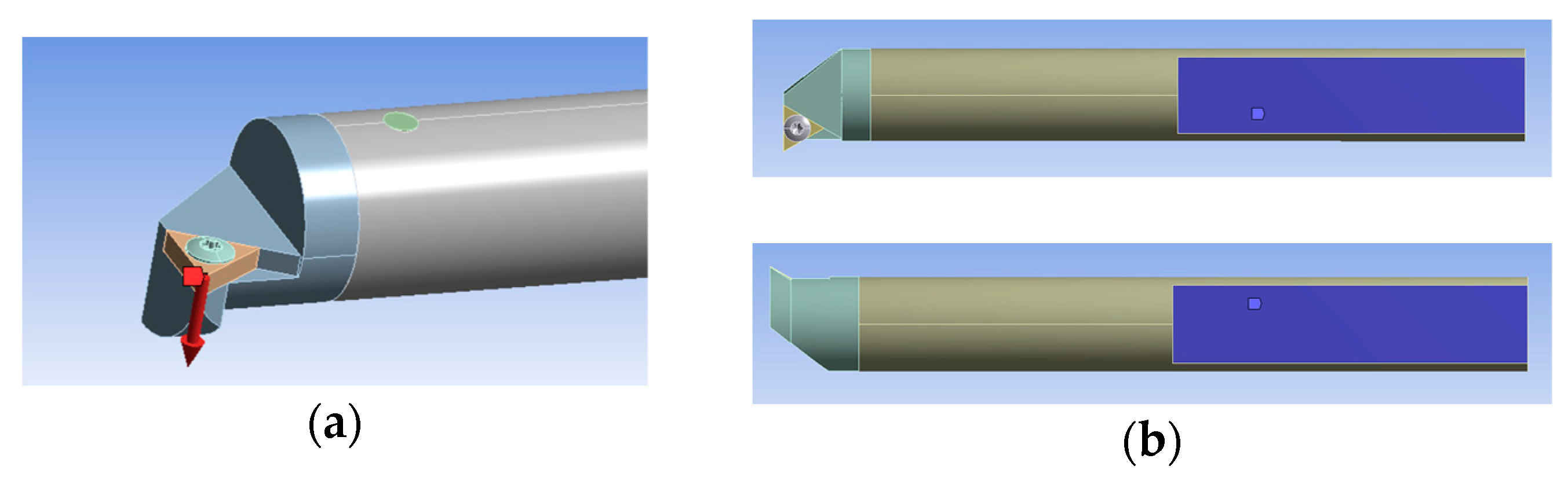
2. Research Methodology
3. Results and Discussion
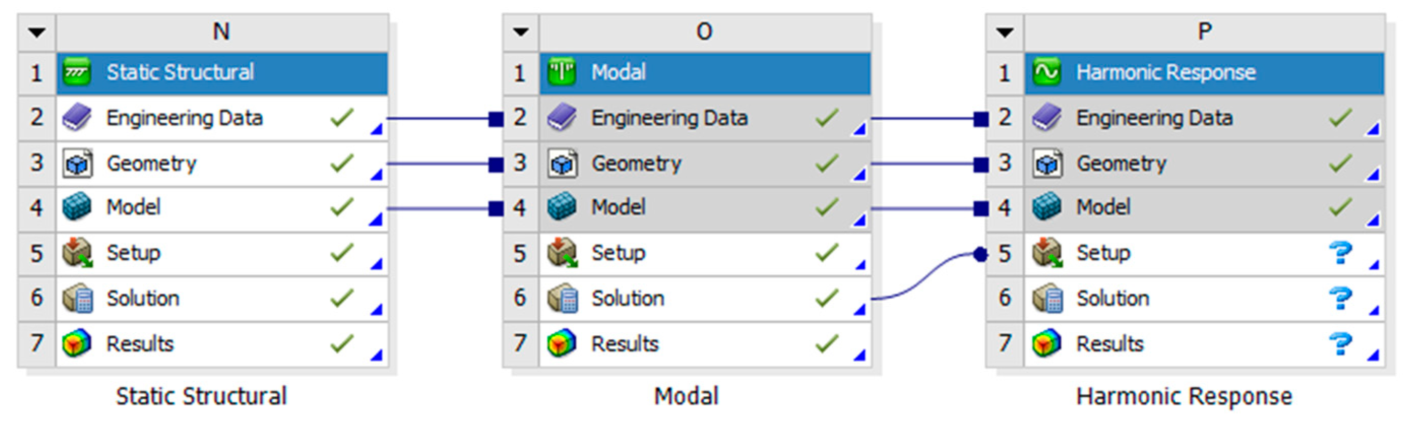
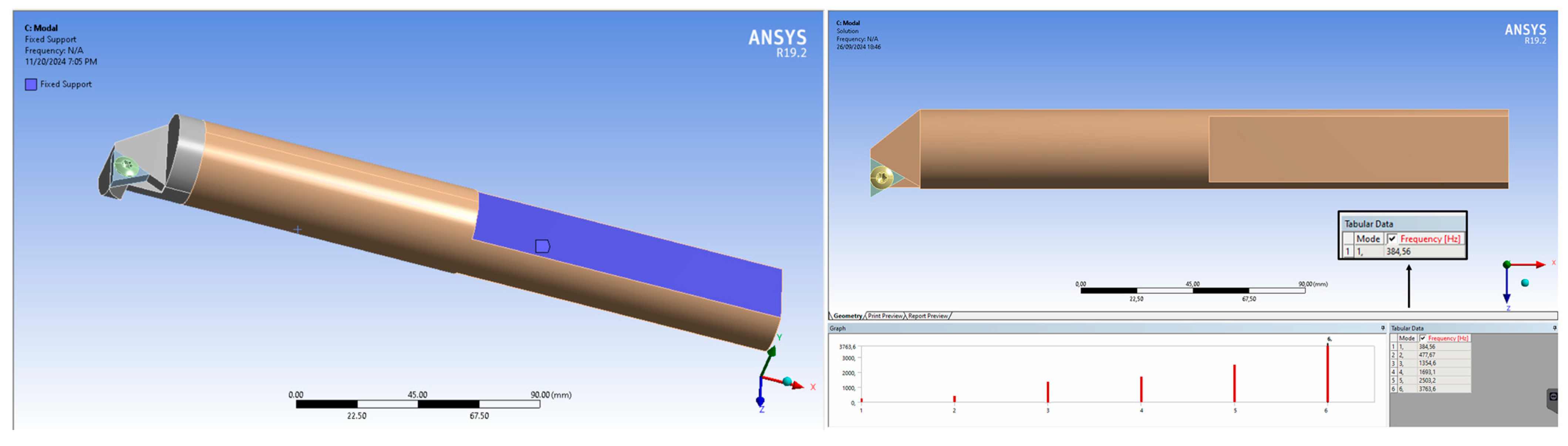
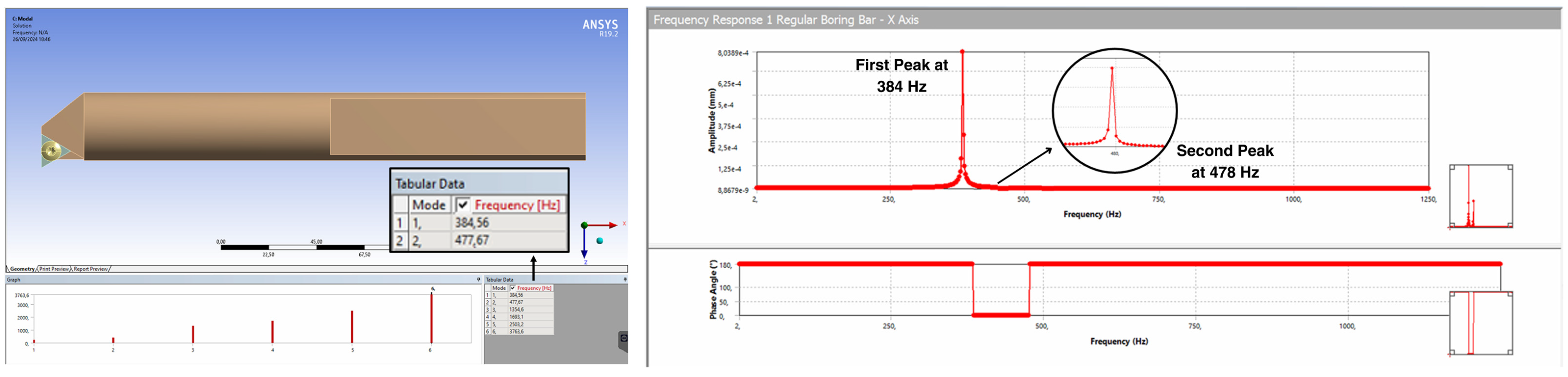
3.1. Analysis of the Relationship Between Modal Analysis and Harmonic Response
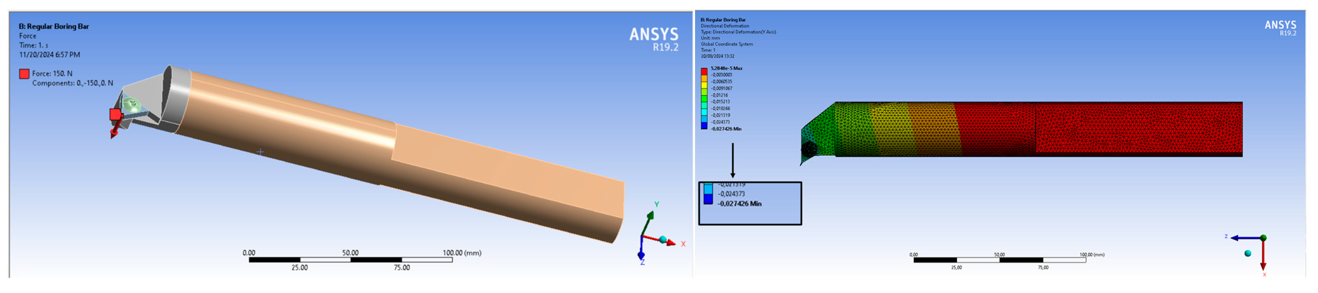
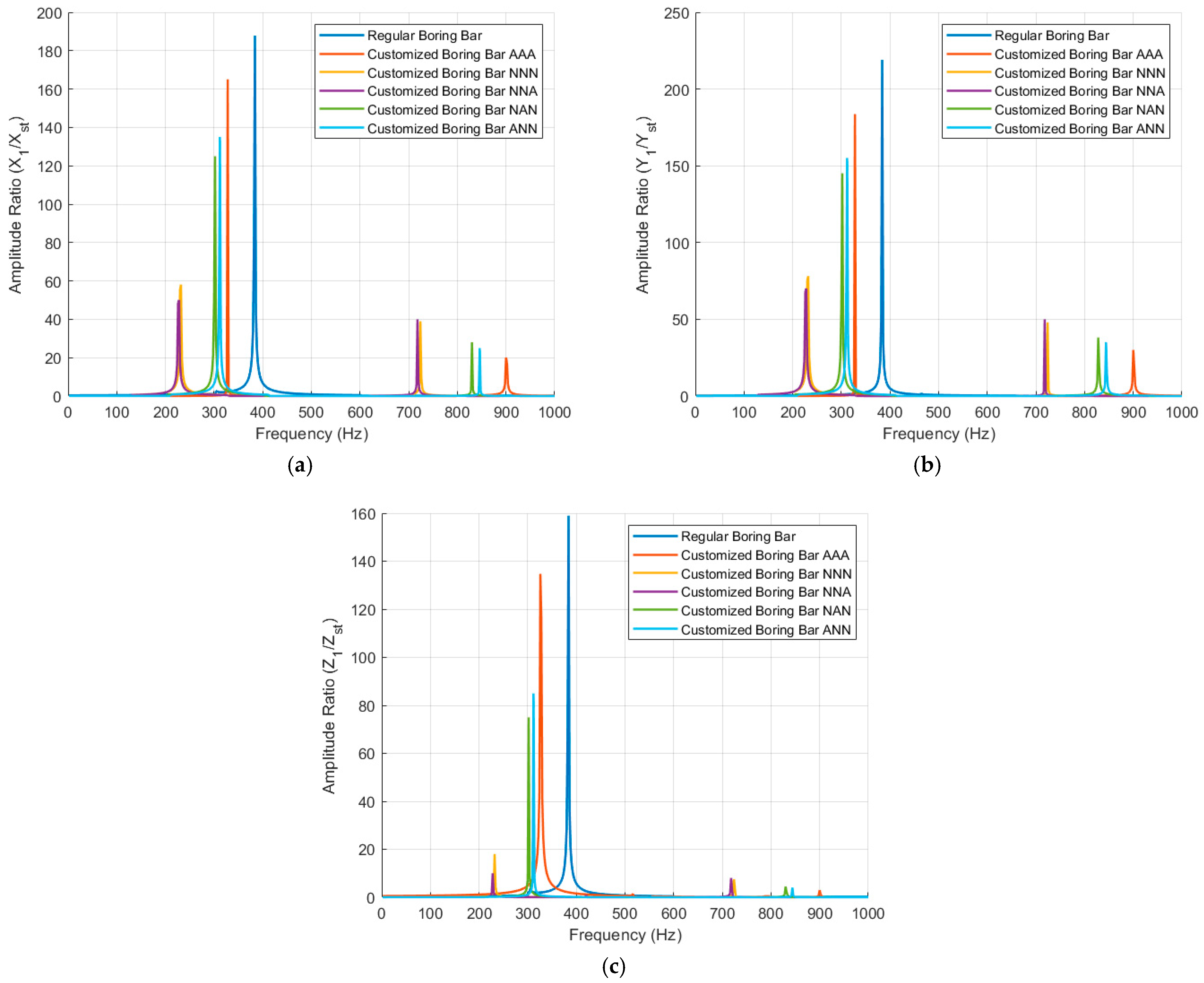
3.2. Analysis of Main System Vibration Response
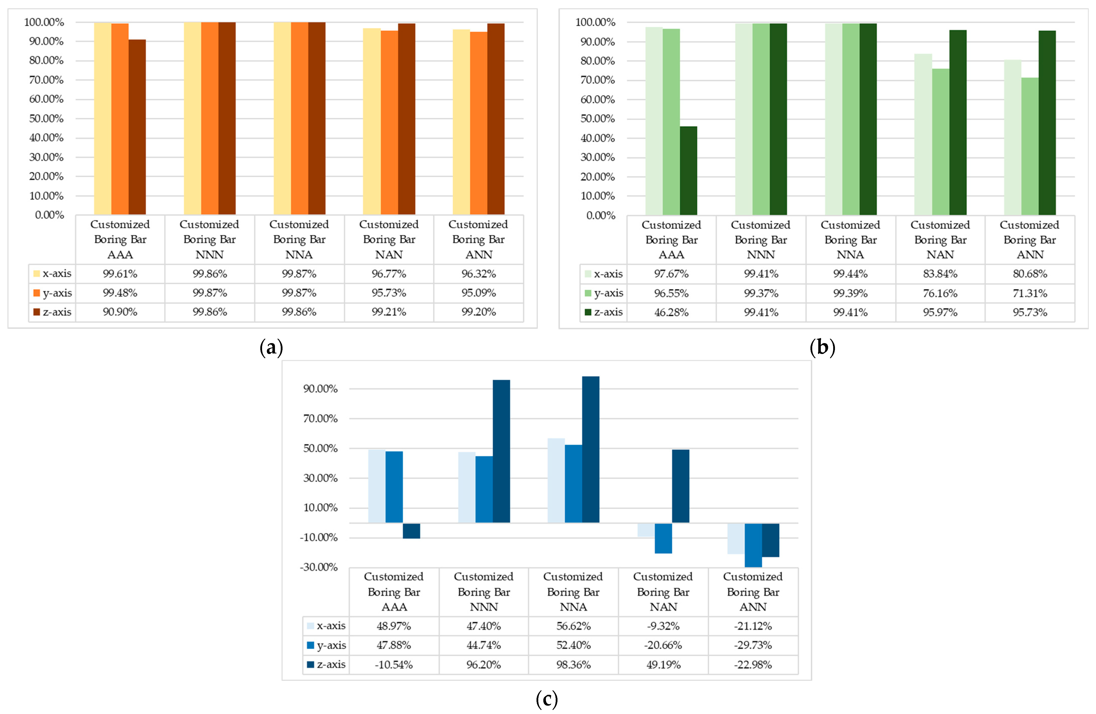
3.3. Vibration Reduction Analysis with Spherical MR-DVAs
4. Conclusions
Author Contributions
Funding
Institutional Review Board Statement
Informed Consent Statement
Data Availability Statement
Conflicts of Interest
References
- Li, L.; Sun, B.; Hua, H. Analysis of the Vibration Characteristics of a Boring Bar with a Variable Stiffness Dynamic Vibration Absorber. Shock. Vib. 2019, 2019, 5284194. [Google Scholar] [CrossRef]
- Anand, T.J.S.; Saptari, A.; Nugroho, W.; Rahman, M.N.A.; Mohamad, E.; Salleh, M.R. Effect of damper positions in reducing vibration for internal turning process. Aeronaut. Aerosp. Open Access J. 2020, 4, 26–32. [Google Scholar] [CrossRef]
- Zheng, L.; Chen, W.; Huo, D. Review of vibration devices for vibration-assisted machining. Int. J. Adv. Manuf. Technol. 2020, 108, 1631–1651. [Google Scholar] [CrossRef]
- Hendrowati, W.; Merdekawan, N. Modeling and Analysis of Boring Bar Vibration Response in Internal Turning Due to Variation of the Amount of DVA Rubber in Finish Boring Cut. J. Mech. Sci. Technol. 2021, 35, 4353–4362. [Google Scholar] [CrossRef]
- Zhang, C.; Ren, Y.; Ji, S.; Zhang, J. Analysis of the composite boring bar dynamic characteristics considering shear deformation and rotational inertia. Appl. Sci. 2020, 10, 1533. [Google Scholar] [CrossRef]
- Liu, X.; Liu, Q.; Wu, S.; Li, R.; Gao, H. Analysis of the Vibration Characteristics and Adjustment Method of Boring Bar with A Variable Stiffness Vibration Absorber. Int. J. Adv. Manuf. Technol. 2018, 98, 95–105. [Google Scholar] [CrossRef]
- Li, L.; Yang, D.L.; Cui, Y.M. Optimization of machining performance in deep hole boring: A study on cutting tool vibration and dynamic vibration absorber design. Adv. Prod. Eng. Manag. 2023, 18, 371–380. [Google Scholar] [CrossRef]
- Bankar, V.K.; Aradhye, A.S. A Review on Active, Semi-active and Passive Vibration Damping. Int. J. Curr. Eng. Technol. 2016, 6, 6. [Google Scholar]
- Lu, X.; Chen, F.; Altintas, Y. Magnetic actuator for active damping of boring bars. CIRP Ann. Manuf. Technol. 2014, 63, 369–372. [Google Scholar] [CrossRef]
- Grossi, N.; Croppi, L.; Scippa, A.; Campatelli, G. A dedicated design strategy for active boring bar. Appl. Sci. 2019, 9, 3541. [Google Scholar] [CrossRef]
- Zhang, C.; Ren, Y.; Ji, S.; Zhang, J. Analysis of the Vibration and Chatter Stability of a Tapered Composite Boring Bar. Shock. Vib. 2020, 2020, 4190806. [Google Scholar] [CrossRef]
- Hayati, S.; Shahrokhi, M.; Hedayati, A. Development of a Frictionally Damped Boring Bar for Chatter Suppression in Boring Process. Int. J. Adv. Manuf. Technol. 2020, 113, 2761–2778. [Google Scholar] [CrossRef]
- Liu, X.; Liu, Q.; Wu, S.; Liu, L.; Gao, H. Research on the performance of damping boring bar with a variable stiffness dynamic vibration absorber. Int. J. Adv. Manuf. Technol. 2017, 89, 2893–2906. [Google Scholar] [CrossRef]
- Thomas, W.; Diniz, A.E.; Pederiva, R.; Suyama, D.I.; De Albuquerque, M.V. A New Type of Impact Damper with Long Overhangs in the Internal Turning of Hardened Materials. In Procedia CIRP; Elsevier B.V.: Amsterdam, The Netherlands, 2019; pp. 255–260. [Google Scholar] [CrossRef]
- Chaari, R.; Djemal, F.; Chaari, F.; Abbes, M.S.; Haddar, M. Experimental Study of Passive Vibration Suppression Using Absorber with Spherical Ball Impact Damper. Proc. Inst. Mech. Eng. C J. Mech. Eng. Sci. 2017, 231, 3193–3201. [Google Scholar] [CrossRef]
- Suryandari, D.A.; Hendrowati, W. Mechanical Engineering and Sciences Numerical Analysis of Translational Vibration Reduction Response on Drilling Process Due to Additional Mass-Rubber Dynamic Vibration Absorber (MR-DVA). 2022. Available online: https://iptek.its.ac.id/index.php/jmes (accessed on 23 November 2024).
- Nwoke, O.N.; Okonkwo, O.C.; Okafor, C.E.; Okokpujie, I.P. Evaluation of Chatter Vibration Frequency in CNC Turning of 4340 Alloy Steel Material. Artic. Int. J. Sci. Eng. Res. 2017, 8, 2. Available online: http://www.ijser.org (accessed on 23 November 2024).


| Spindle Speed (rpm) | Feed Rate (mm/rev) | Depth of Cut (mm) | Chatter Frequency (ωc) |
|---|---|---|---|
| 320 | 0.1 | 0.2 | 388 |
| 450 | 0.1 | 0.2 | 366 |
| 720 | 0.1 | 0.2 | 318 |
| Parameter | Stiffness (N/m) | Mass (kg) | Damping (Ns/m) | Natural Frequency (Hz) |
|---|---|---|---|---|
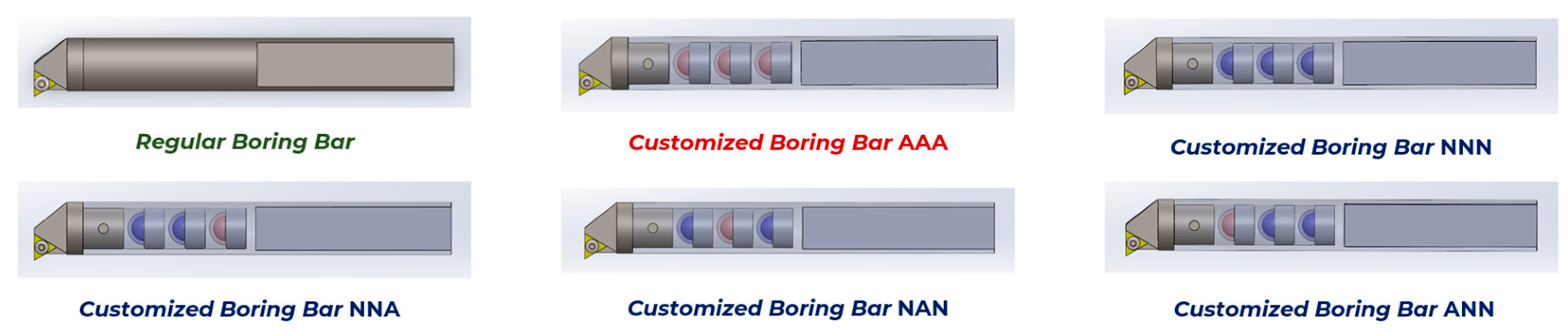
| Regular boring bar | 0.55 × 10⁷ | 0.942 | 22.76 | 384.56 |
| Customized boring bar | 0.42 × 10⁷ | 0.701 | 17.16 | 389.44 |
| DVA natural | 0.39 × 10⁷ | 0.00149 | 1.335 | 3571.2 |
| DVA neoprene | 0.49 × 10⁷ | 0.00154 | 3.651 | 9426.6 |
Disclaimer/Publisher’s Note: The statements, opinions and data contained in all publications are solely those of the individual author(s) and contributor(s) and not of MDPI and/or the editor(s). MDPI and/or the editor(s) disclaim responsibility for any injury to people or property resulting from any ideas, methods, instructions or products referred to in the content. |
© 2025 by the authors. Licensee MDPI, Basel, Switzerland. This article is an open access article distributed under the terms and conditions of the Creative Commons Attribution (CC BY) license (https://creativecommons.org/licenses/by/4.0/).
Share and Cite
Nuha, A.U.; Hendrowati, W. Numerical Analysis of Boring Bar Vibration Response in Internal Turning with Spherical Mass–Rubber Dynamic Vibration Absorber (MR-DVA). Eng. Proc. 2025, 84, 45. https://doi.org/10.3390/engproc2025084045
Nuha AU, Hendrowati W. Numerical Analysis of Boring Bar Vibration Response in Internal Turning with Spherical Mass–Rubber Dynamic Vibration Absorber (MR-DVA). Engineering Proceedings. 2025; 84(1):45. https://doi.org/10.3390/engproc2025084045
Chicago/Turabian StyleNuha, Aufa Ulin, and Wiwiek Hendrowati. 2025. "Numerical Analysis of Boring Bar Vibration Response in Internal Turning with Spherical Mass–Rubber Dynamic Vibration Absorber (MR-DVA)" Engineering Proceedings 84, no. 1: 45. https://doi.org/10.3390/engproc2025084045
APA StyleNuha, A. U., & Hendrowati, W. (2025). Numerical Analysis of Boring Bar Vibration Response in Internal Turning with Spherical Mass–Rubber Dynamic Vibration Absorber (MR-DVA). Engineering Proceedings, 84(1), 45. https://doi.org/10.3390/engproc2025084045