1. The Role of Carbon Fiber Composites in Modern Aviation
In the ongoing evolution of civil aircraft design, reducing the airframe weight while maintaining structural integrity has become a core objective, as it directly influences fuel efficiency and performance metrics, such as the thrust-to-weight ratio. Modern aircraft design demands not only lightweight structures but also a long service life, high efficiency, and sustainability. However, traditional metal materials, although reliable, are increasingly unable to fully meet these expanding requirements. This has led to a growing interest in alternative materials that can fulfill these demands more effectively. Composite materials stand out for their high strength, fatigue resistance, corrosion resistance, and numerous other advantages. As research deepens and the application of composite materials widens, these technologies and their characteristics are becoming crucial in realizing the developmental goals of a new generation of high-performance aircraft.
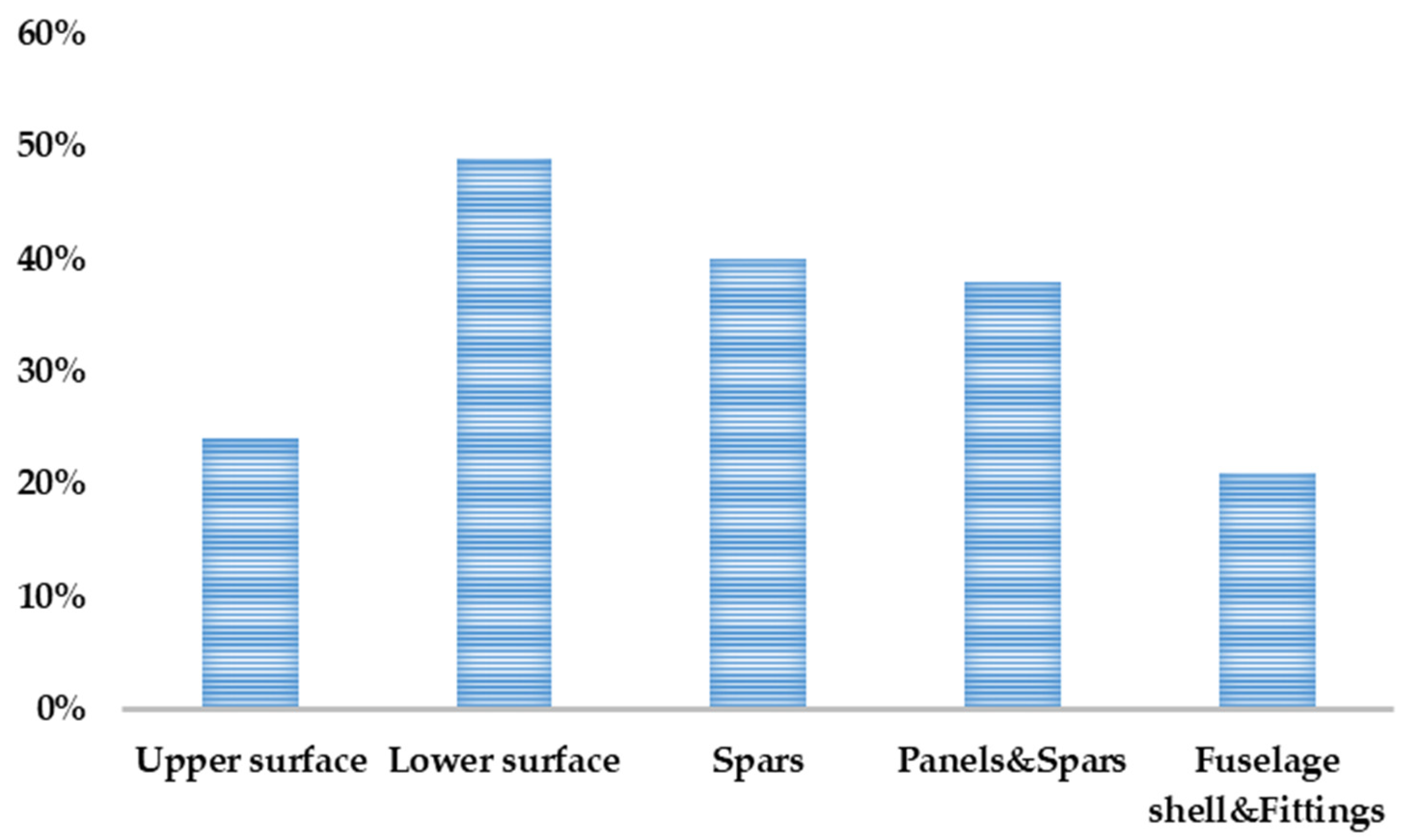
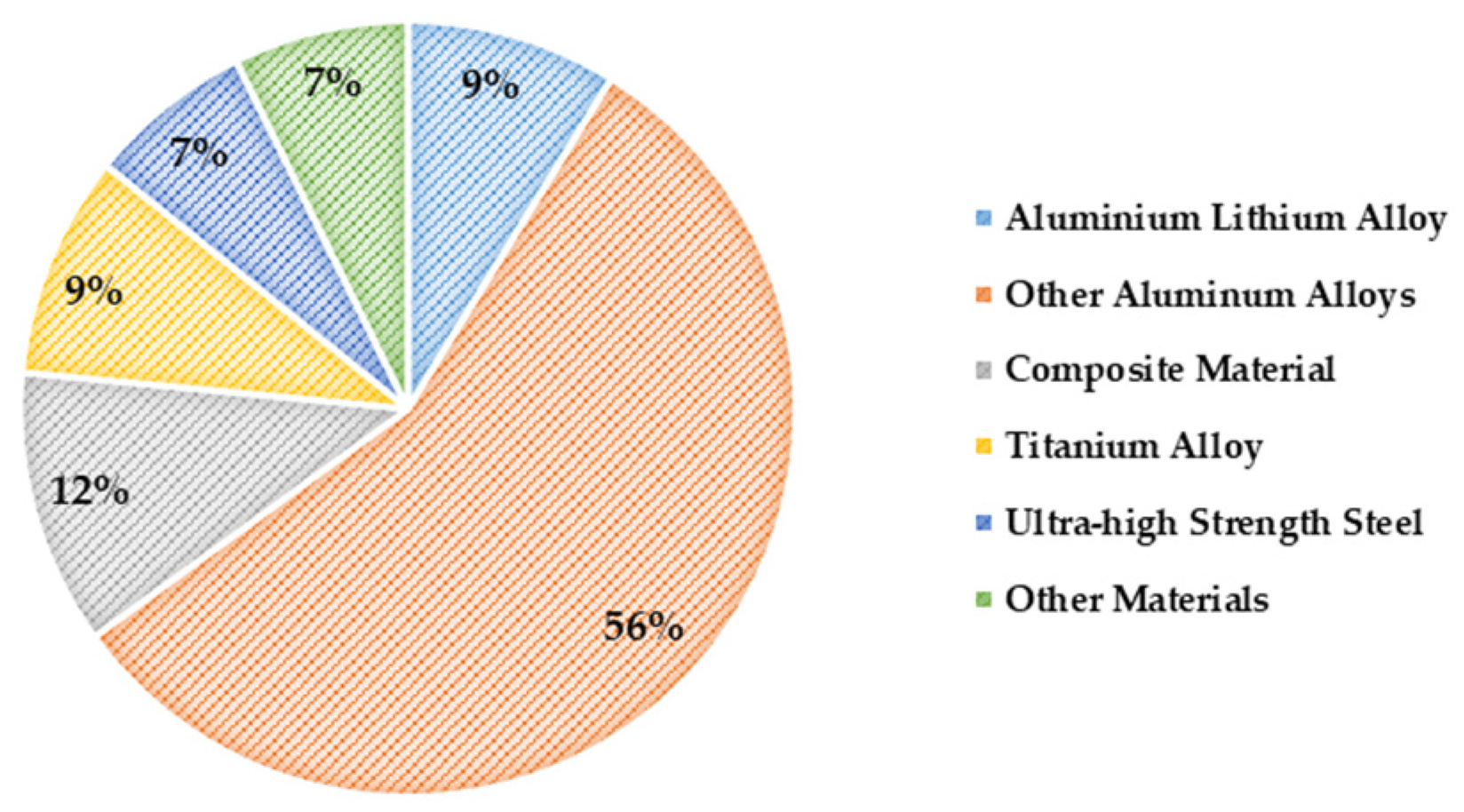
Carbon fiber-reinforced polymer (CFRP) is a high-performance composite material composed of carbon fibers and a polymer matrix. Carbon fiber, renowned for its high strength, modulus, and low density, is typically derived from organic polymers, such as polyacrylonitrile (PAN) or petroleum pitch, through high-temperature processing. The polymer matrix, often made from epoxy, polyester, or vinyl ester resins, binds the carbon fibers together, providing structural support to the composite and effectively transferring loads. The exceptional properties of CFRP include a high strength-to-weight ratio, surpassing that of aluminum alloys, making it crucial for reducing aircraft weight, which in turn improves fuel efficiency and flight performance [
1], as illustrated in
Figure 1. Furthermore, the material exhibits excellent stiffness and corrosion resistance, ensuring that it remains undeformed under stress and can endure harsh environments over extended periods without corroding. Additionally, CFRP has an outstanding fatigue resistance and a low coefficient of thermal expansion, making it highly stable under repeated loads and temperature variations.
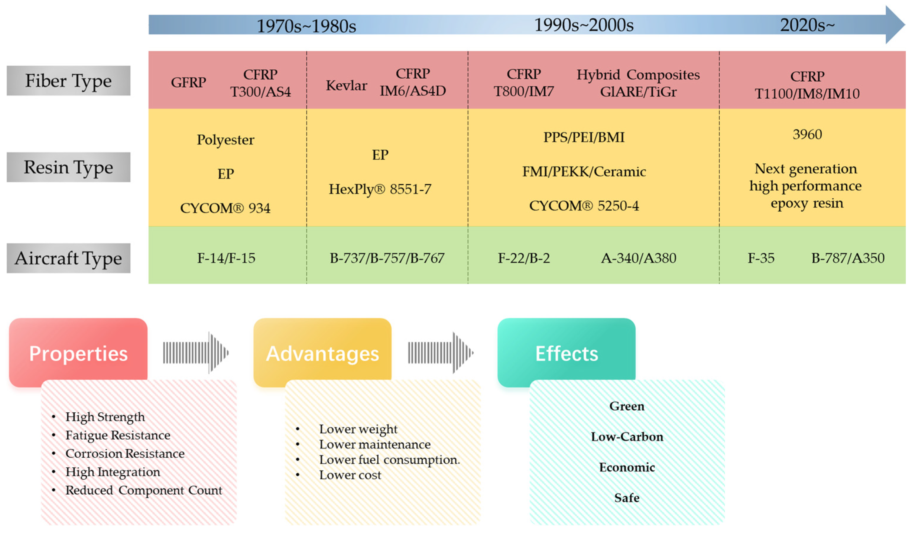
Since the 1970s, aviation carbon fiber composites have undergone three generations of material development: high-strength standard modulus carbon fiber reinforced with brittle epoxy resin composites in the 1970s and 1980s, high-strength medium modulus carbon fiber reinforced with ductile epoxy resin composites in the 1990s, and ultra-high strength medium modulus carbon fiber reinforced with ductile composites after 2010 [
2], as illustrated in
Figure 2. These advancements in material development have enabled the progressive application of composite materials, evolving from small components to large structures, from secondary to primary load-bearing structures, and from purely structural roles to multifunctional applications. Consequently, these materials have been pivotal in driving aircraft design toward more sustainable, low-carbon, economical, and safe solutions.
Since the 1960s, CFRP has gradually been established in aircraft structural design due to its unique properties, leading to its expanding application range. In the mid-1970s, Airbus made an attempt to apply composite materials to its A-300 series aircraft. In the A-310 series, composite materials were more widely applied to non-critical, weight-reducing components, further unlocking their potential in aircraft structures. In the 1980s, Airbus achieved a notable advancement by successfully applying an all-composite vertical tail to the A-320 model. This development thus laid a foundation for the future application of composite materials in aircraft. Since then, Airbus has continued to integrate composites into its designs, with the A-300 series tail components fully adopting these materials, increasing their proportion in the aircraft to about 15%. As time progressed, Airbus applied composite materials to key areas, such as the wing structure and tail in the A-330 and A-340 series. Although the proportion of composite materials remained under 20%, this initiative reduced aircraft weight and improved performance, demonstrating the potential of composite materials. The introduction of the Airbus A-350 XWB marked a significant point in the application of composite materials. More than 50% of the aircraft’s structure is composed of composite materials, particularly with the wings being fully CFRP, which improves the strength-to-weight ratio and underscores the role of composite materials in modern aircraft design. Composite materials also play a crucial role in the A-380, a large commercial airliner. About 25% of the overall weight comes from composite materials, which are used in key parts, such as the rear fuselage, center wing box, and horizontal and vertical tail surfaces [
3].
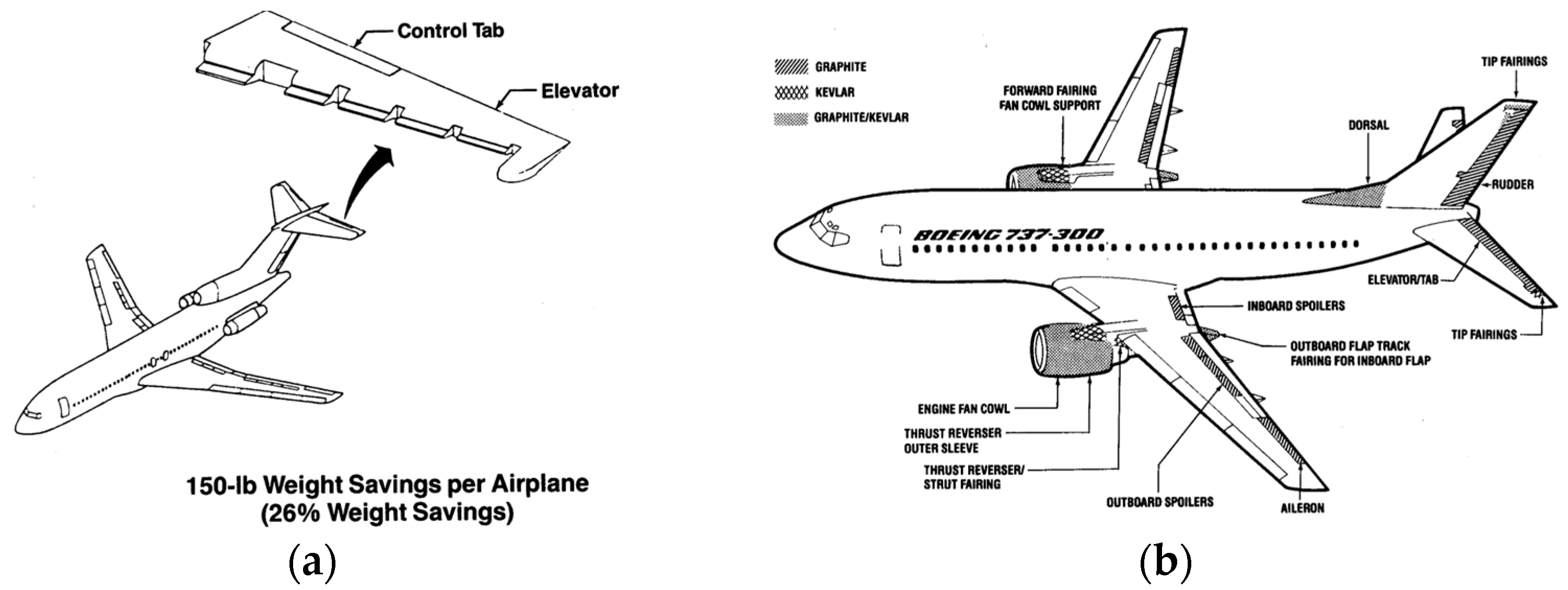
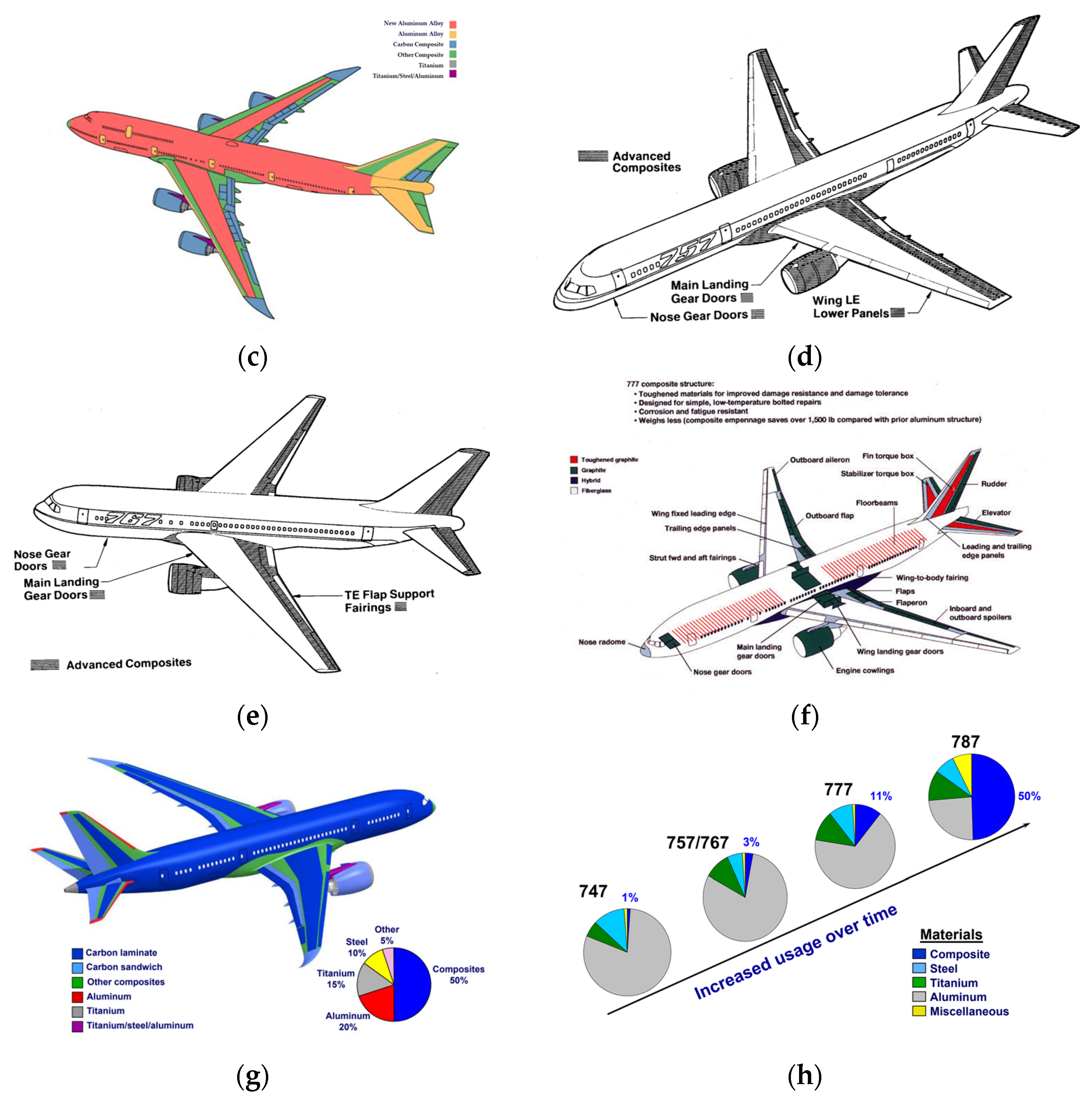
In the middle of the 20th century, Boeing, a major player in the aviation industry, recognized the potential of composite materials and began exploring their use in aircraft design [
4,
5,
6]. This exploration began with the B707, where about 2% of the aircraft’s structure was composed of fiberglass components. Although this initial application was limited, it set the stage for further research into composites and laid the groundwork for future applications. In the 1970s, Boeing entered a new phase of composite material usage with the B737, incorporating carbon fiber composites into key aerodynamic components, such as spoilers and horizontal tail fins. With the introduction of the B747 series, Boeing expanded the use of composite materials. In early models like the B747-100, B747-200, and B747-300, composites were primarily used in secondary structures, such as fairings and control surfaces. As composite technology advanced, Boeing increased their use in the B747-400, particularly in the tail and control surfaces, which improved aerodynamic efficiency and fuel economy. Over time, Boeing’s application of composite materials became more sophisticated. The B747-8, while not using composites to the same extent as the B787, effectively incorporated them in critical areas like fairings, flight control surfaces, and floor beams, contributing to weight reduction and performance enhancement. This experience provided valuable insights for future aircraft designs. The B777 series marked another significant step forward in Boeing’s use of composites. The increased use of these materials in the tail and control surfaces led to improvements in fuel efficiency and overall performance. The B777-X further expanded the use of composites, especially in the wings, resulting in a lighter, stronger structure with improved aerodynamic efficiency. The B787 Dreamliner represents a milestone in Boeing’s composite material strategy. As the first commercial aircraft to extensively use composite materials, approximately 50% of the B787’s structure is composed of these advanced materials, including the fuselage, wings, tail, doors, and internal structures. This substantial use of composites reduced the aircraft’s weight and improved fuel efficiency by about 20%. Each B787 contains around 32,000 kg of CFRP, highlighting the maturity of composite materials in aviation and pointing to the future direction of aircraft design focused on efficiency and sustainability.
Figure 3 shows the application of CFRP in the Boeing family of aircraft.
The Commercial Aircraft Corporation of China (COMAC) successfully launched the C919 narrow-body passenger jet, marking a significant milestone in China’s commercial aircraft sector. The C919 is notable for its innovative fuselage structural design and extensive use of advanced materials, with CFRP accounting for approximately 12 percent of the aircraft’s structure. These advanced CFRP components are employed not only in critical aerodynamic and control surfaces, such as the rudder, horizontal tail, and vertical tail, but also in secondary load-bearing structures. This application enhances the aircraft’s structural integrity while reducing its overall weight, leading to improved fuel efficiency, lower operating costs, and enhanced flight performance and reliability [
7].
Figure 4 shows the application of various materials on the C919.
The application of carbon fiber composite materials in the design of electric vertical take-off and landing (eVTOL) aircraft has brought advancements to this emerging field. These high-tech materials have not only transformed the construction of eVTOL aircraft but also enhanced their overall performance and operational efficiency. CFRP is extensively used in critical load-bearing components, such as the fuselage, center wing, outer wing, and tail, owing to its exceptional strength-to-weight ratio. The integration of CFRP allows for a substantial weight reduction while maintaining structural integrity, directly improving flight efficiency and reducing energy consumption. The landing gear, a crucial component for safe takeoff and landing, also benefits from the use of CFRP. The robust and lightweight design of the landing gear enhances stability and safety while optimizing the overall weight distribution of the aircraft. In the propulsion system, CFRP is vital in reducing the weight and increasing the durability of components, such as propellers and motor casings, ensuring a long-lasting and efficient operation. The passenger compartment design further demonstrates the advantages of CFRP. Components like wall panels, seat backboards, floors, and storage compartments are made from CFRP, meeting the dual demands of lightweight and high strength while also improving safety, aesthetics, and comfort. The high crashworthiness and flame retardancy of CFRP provide a safer environment for passengers.
3. Heat Transfer Model
3.1. Energy Equation
Mathematical modeling has become an indispensable methodology in order to efficiently and economically evaluate the fire performance of composite materials and the dynamic response of their structures in fire environments. Such models reduce the need for expensive and time-consuming actual fire tests, and while they cannot yet replace experimental validation, they have become an aid in exploring the fire behavior of traditional polymer composites and facilitating the development of new high-performance refractory materials. In recent decades, progress has been made in the field of composite fire response simulation, especially in the prediction of the fire behavior of laminate and sandwich composites. Researchers have built a series of advanced mathematical models that predict the temperature change, pyrolysis kinetics, softening behavior and ultimate failure mechanism of composite materials during fire, and further extend to the evaluation of the mechanical properties of materials after fire. These mathematical tools not only deepen the understanding of the structural response of composite materials under fire conditions, but also provide a solid theoretical basis for engineering design and material improvement. In the process of model construction and optimization, it is essential to accurately analyze and characterize multi-scale and multi-physics coupling processes, such as heat conduction, chemical reaction, physical deformation and structural failure. These processes are interwoven and, together, shape the complex combustion properties of composite materials in fires, so a deep understanding of their interactions is a prerequisite for ensuring the accuracy of model predictions. Specifically, in a fire scenario, the composite is typically exposed to one side of the flame, while the other side is in contact with the ambient air, creating a significant temperature gradient. As heat is transferred from the fire source to the interior of the material, the matrix resin and the reinforced fiber will undergo a series of complex reactions, such as heat transfer, phase transition, pyrolysis carbonization, thermal expansion/contraction, internal pressure accumulation, delamination damage, surface denudation and possible combustion, which together determine the final performance and failure mode of the material.
The theoretical basis of the field of thermal analysis of composite materials in fire can be traced back to the mid-1940s, when scientists conducted in-depth theoretical research on wood combustion behavior. These pioneering works have laid a solid foundation for understanding transient heat transfer, pyrolysis dynamics, and the flow and combustion of volatile gases during combustion. Kung [
10], Kansa et al. [
11], and Fredlund [
12] proposed thermochemical models of wood combustion, which analyzed the heat transfer and pyrolysis reaction pathways of wood surfaces in fire environments, as well as the convection and combustion mechanism of volatile products in flames. With the increasing application of composite materials in aviation, aerospace, construction and other fields, researchers have begun to extend the concept and method of wood combustion model to the fire behavior analysis of composite materials. Henderson et al. [
13,
14,
15,
16,
17] introduced the unique thermal and physical property parameters and decomposition mechanism of composite materials, adapted and optimized the original model, and significantly improved the accuracy of the model in predicting the fire response of composite materials. Sullivan et al. [
18,
19,
20], Mcmanus et al. [
21,
22] and Dimitrienko et al. [
23,
24] also contributed a lot of work successively, further refining the description of the pyrolysis process of composite materials in fire, taking into account the comprehensive influence of various thermophysical phenomena. However, a major limitation of the early models was that they generally simplified the interaction between the flame and composite material, that is, the decoupling analysis between the flame and material was realized. Although this approach is convenient for mathematical processing, it ignores the direct effects of flame turbulence, radiation and convective heat transfer on the surface temperature distribution of composite materials and fails to fully consider the flow and combustion characteristics of volatile gases on composite materials. These neglected interactions are crucial for accurately predicting the response of composites in real fire scenarios. To overcome this limitation, Luo et al. [
25,
26] proposed a fluid–structure coupling modeling approach. This method applies computational fluid dynamics (CFD) technology to the fire analysis of composite materials to capture the dynamic characteristics of the flame and its complex heat transfer process to the surface of composite materials through high-precision numerical simulation. At the same time, the mesh embedding technology is used to realize the seamless connection between the flame and the solid material interface, so that the multi-scale and multi-physical field coupling of composite materials can be simulated more accurately as they occur in fire environments.
Henderson et al. [
13] built a widely used mathematical model to calculate the temperature distribution of composite materials in fire environments. The model took into account the heat transfer of energy in the direction of material thickness and integrated the absorption and exothermic effect of the polymer decomposition process and the comprehensive influence of volatile gas flow on the internal temperature evolution of composite materials. The first term on the right of Equation (1) considers the heat conduction in the direction of thickness, the second term refers to the heat released by the outflow of pyrolysis gas, and the third term considers the heat released due to the pyrolysis reaction. The energy changes in the second and third terms are mainly affected by the thermal decomposition rate of the material.
where
ρ: the instantaneous density of the material;
cp: the specific heat capacity of the material, which represents the heat absorbed or released per unit mass of the material when the temperature changes;
T: temperature, which represents the temperature of the material;
k: the current thermal conductivity of the composite, which represents the material’s ability to conduct heat;
ṁg: the volatile gas mass flux, which represents the mass flow rate of the volatile gas;
x: represents the distance along the thickness of the exposed surface;
t: time;
Q: the decomposition energy of the polymer matrix, which represents the heat released by the decomposition reaction;
h: the enthalpy of the composite, which represents the internal energy of the material; and
hg: the enthalpy of a volatile gas, which represents the internal energy of a volatile gas.
On this basis, Gibson et al. [
27] made a revision and extension of the original heat transfer equation. By introducing the description of the decomposition reaction rate of the polymer matrix, they further improved the thermal behavior model of composite materials in fire environments. This revision not only takes into account the influence of heat conduction and volatile gas flow on temperature, but also emphasizes the important role of the heat released or absorbed during the decomposition of the polymer matrix on the internal temperature distribution of the composite. By integrating the Arrhenius equation, the decomposition reaction rate of the polymer matrix is quantified and incorporated into the equation as a source term, so that the model can more accurately simulate the dynamic change process of the internal temperature of the composite material under the ignition condition:
The last term of the above formula, the decomposition term, specifically defines the pyrolytic reaction rate of the polymer matrix under fire conditions. This key correction allows the model to reflect the complex thermochemical reactions that occur inside the composite during fire more realistically. The reaction rate constants (A, E, n) in the decomposition term are the core parameters in the model calculation. They represent the pre-factor, the activation energy and the reaction order, respectively. These parameters are important for accurately describing the decomposition kinetics of the polymer matrix. In order to obtain these key parameters, thermogravimetric analysis (TGA) is usually used. TGA is a thermal analysis technique that measures the relationship between the mass of a substance and the change in temperature by programming the temperature. It can measure the mass loss of a material at different temperatures and calculate the kinetic parameters of the decomposition reaction based on it.
In the study by Florio et al. [
16], they constructed a more complex energy conservation model, which not only covers the classical processes of heat transfer, flow and polymer matrix decomposition, but also takes into account the thermal expansion effect caused by the formation of volatile gases and its influence on the internal pressure of the material. This extension enhances the model’s ability to describe complex thermal behavior of composites under fire conditions:
The first term on the right side of the equation represents the heat transfer due to mass flow per unit time, and this term reflects the contribution of heat carried by volatile gases as they flow inside the material to the temperature field. Under fire conditions, the volatile gas produced by the decomposition of the polymer matrix will flow inside the material and remove or bring heat, thus affecting the local temperature distribution. The heat transfer is related to changes in material structure, and this describes the heat transfer effect caused by changes in the material microstructure (such as pore formation, stratification, etc.). These structural changes will affect the heat conduction path and efficiency, and then change the overall temperature distribution of the material. The third item on the right side of the equation determines the net rate of convective energy transfer of volatile gases. This item quantifies the heat transfer rate of volatile gases in the composite material by convection. In the process of a fire, the convective movement of volatile gases is one of the important ways of heat transfer and has a significant impact on the dynamic changes in the material temperature field. The fourth item on the right side of the equation represents the work rate of thermal expansion, which takes into account the contribution of the work to the conservation of energy when the material thermal expansion occurs due to the rise in temperature. During the thermal expansion process, the material will produce stress and strain, thereby releasing or absorbing energy, affecting the stability of the temperature field. The last term on the right of the equation represents the heat energy released or absorbed by the matrix decomposition reaction. Heat energy is released or absorbed by the matrix decomposition reaction, which directly reflects the influence of the decomposition reaction of the polymer matrix on the temperature field under fire conditions; the decomposition reaction may absorb or release a lot of heat, which plays a key role in the temperature distribution of the composite material.
3.2. Physical Property Parameters
In order to accurately predict the thermal response characteristics of composite materials, physical property parameters, such as density, thermal conductivity and the specific heat capacity of the material within the temperature range of interest, must be understood and mastered. The change in these parameters will directly affect the heat transfer characteristics, thermal expansion behavior and mechanical properties of the material under high temperature conditions.
3.2.1. Density
Density not only affects the bulk mass of the composite material but is also closely related to its heat capacity. In a fire or other high temperature environments, with the increase in temperature, the polymer matrix in the composite material will gradually decompose and produce volatile gases, resulting in a decrease in the overall density of the material. In this process, the change in density will affect the thermal inertia of the material, that is, the speed at which the material responds to changes in temperature. In the process of the thermal decomposition of composite materials, the decrease in density is caused by the decomposition of the polymer matrix and the release of volatile products. Arrhenius kinetics, as a core concept, plays an important role in the field of materials science and chemical engineering when studying the decomposition behavior of materials under high temperature conditions. This method is specifically used to describe the thermal decomposition kinetics of materials during heating, that is, the process of the material gradually breaking down into different components at high temperatures with the accompanying heat release. At the heart of the mathematical modeling of this process lies the Arrhenius equation, which is expressed as:
where
k: the decomposition reaction rate, which is a key parameter to measure the speed of material decomposition;
A: the Arrhenius factor, which reflects the intrinsic frequency at which the reaction occurs at a given temperature and is closely related to the geometry and frequency of collisions between the reactant molecules, depending on the specific details of the reaction;
Ea: the activation energy, which is the minimum energy necessary for an intermolecular reaction to cross the energy barrier and determines how sensitive the reaction rate is to changes in temperature. A higher activation energy means that the reaction is less sensitive to changes in temperature, thus requiring a higher temperature to trigger a significant decomposition reaction rate;
R: the universal gas constant, which is a fundamental constant in thermodynamics; and
T: the absolute temperature and is the thermodynamic environment parameter in which the reaction occurs.
The Arrhenius equation reveals the positive correlation between the decomposition reaction rate and temperature, that is, the decomposition reaction rate increases significantly with the increase in temperature. Based on the Arrhenius equation, we can describe the change in density during this process by the following formula:
In the formula, ρv and ρch represent the density of the composite material in the initial (undecomposed) state and the final transformation (such as carbonization) state, respectively. These two parameters define the range of density change, that is, the transition process of the material from the initial state to the final transformation state. Reaction order n is a sensitivity index to describe how the reaction rate changes with the density change. When n = 1, the expression of density change is simplified to a linear proportional relationship, which directly reflects the position of the current density ρ relative to the maximum range of its possible change (ρv to ρch). This setting physically means that when ρ is close to ρ, it indicates that the material has just begun to undergo the decomposition process, its state has not yet been significantly transformed to the carbonized state, and the reaction rate is relatively low; when ρ is close to ρch, it indicates that the decomposition of the material is close to completion, and most of it has been converted into carbonized substances. At this time, although the reaction rate is reduced due to the reduction in the remaining reactive substances, the overall change has approached the end. Further, the density difference (ρ−ρch) in the density ρ times the reaction rate term reflects the direct effect of the material density on its decomposition rate. Implicit in this formulation is the proportional relationship between mass loss and the amount of material present, i.e., during thermal decomposition or chemical reaction, the reaction rate of a material is often proportional to its remaining reactive portion. This assumption is common and valid when dealing with simple first-order reaction kinetics, as it simplifies the description of complex reaction processes while preserving the key kinetic features.
3.2.2. Thermal Conductivity
There have been a considerable number of theoretical and experimental studies on the thermal properties of composites before and after the decomposition transition, especially thermal conductivity and specific heat capacity, focusing on their state before the decomposition [
28,
29,
30,
31,
32,
33]. However, data on thermal properties of composites during the decomposition process, especially during the key stage of transformation from the original state to carbon layer, are still insufficient. Before decomposition, the thermal properties of composites are mainly reflected in the characteristics of their original materials. And after complete decomposition, it is transformed into the characteristics of carbon material. Therefore, for the composite material in the decomposition process, its thermal properties are generally considered to be a mixture of the original composite material and the thermal properties of the completely decomposed carbon material, and the degree of mixing depends on the relative mass fraction of the two. In order to quantify this transformation process, a decomposition progress variable
F is defined, as shown in Equation (6), which evaluates the degree of decomposition based on the changes in material density:
Using this progress variable, the thermal conductivity
k(
T) of the composite in the decomposition process can be derived, as shown in Equation (7), which is calculated by the weighted average thermal conductivity of the original composite and the carbon layer:
The study by Lattimer et al. [
34] provides valuable data on the thermal conductivity of fiberglass laminates and their carbon layers as a function of temperature (as shown in Equations (8) and (9)), which is important in simulating the thermal response of composites under extreme conditions, such as a fire. However, it should be noted that not all composites are supported by similarly detailed data, so the relationship between thermal conductivity and the temperature of a specific composite usually needs to be described by experimental measurements combined with empirical curves.
In addition, Dimitrienko et al. [
23] proposed an alternative method for calculating thermal conductivity with temperature (Equation (10)), but this method has not been sufficiently validated in thermal decomposition composites. Krysl et al. [
35] and Tranchard et al. [
36] also proposed calculation models for the thermal conductivity of the carbon layer (Equation (11)) and composite material during decomposition (Equation (12)), respectively. These models provide different perspectives for understanding the heat transfer mechanism of composites during the decomposition process.
It is important to note that as the decomposition process progresses, stratification may occur inside the composite material, and these stratifications slow down the heat transfer by forming an air gap between the disadhesive layers, thus reducing the overall thermal conductivity. However, most existing thermal models tend to ignore this effect, leading to biased predictions of the temperature distribution inside the material. For this reason, Luo and DesJardin [
37] developed a thermal conductivity calculation model considering the effect of stratification (Equation (13)), where
k⊥ is the thermal conductivity perpendicular to the boundary. The model corrects the calculation of thermal conductivity by introducing the crack volume fraction, where the crack volume fraction depends on the crack density and crack width.
3.2.3. Specific Heat Capacity
The specific heat capacity of composite materials, as a key parameter to measure the ability of heat absorption or heat release, also undergoes significant changes during the decomposition and transformation process. The specific heat capacity
cp(
T) can be estimated by a weighted average of the specific heat capacities of the original composite and the fully decomposed carbon material, as shown in Equation (14):
According to Henderson and Wiecek [
13], the specific heat capacities of both the original composite and carbon vary with temperature and can be described by linear equations, as shown in Equations (15) and (16):
Similarly to thermal conductivity, the specific heat capacity of the original composite and carbon must also be measured experimentally and precisely over the temperature range of concern, and the measurements must be fitted to the above equations to ensure the accuracy of the model predictions. In addition, the thermal properties of the composite may also be affected by fire, such as the occurrence of delamination and cracking, which further increases the complexity of the prediction of specific heat capacity. Therefore, the effects of these factors should be fully taken into account when simulating the thermal response of composites under extreme conditions, such as fire.
3.3. Boundary Conditions
In composite fire response simulations, it is critical to accurately describe the thermal boundary conditions of composite surfaces exposed to fire. These boundary conditions are often specified by the heat flux, as shown in Equation (17), which expresses the relationship between the heat flux and the temperature gradient:
where
qs,0 is the heat flux at the boundary.
The surface net heat flux of a composite is a combination of the radiative and convective components, calculated by:
where
εs is the surface emissivity,
qrad is the possible external radiant heat source,
σ is the Stefan–Boltzmann constant,
Ts is the surface temperature,
T∞ is the ambient temperature, and
hconv is the convective heat transfer coefficient.
For the side of the composite that is not exposed to fire, the boundary conditions are, likewise, assumed to consist of convection and radiation, as shown in Equation (19):
where
qs,L is the heat flux of the unexposed side and
ε is the environmental emissivity (which can be reduced to 0 in some cases).
In recent years, significant progress has been made in the field of fire response simulations of composite materials. By building complex thermodynamic models, researchers have successfully predicted key phenomena, such as temperature distribution, material decomposition, the softening and eventual failure of laminate and sandwich composites in fire. With the widespread application of polymer composites in aerospace and other engineering fields, corresponding heat transfer models have been significantly developed, especially in predicting the fire behavior of composites containing inactive fibers. However, the fire response simulation of composites containing active fibers, such as carbon fiber and Kevlar fiber, remains challenging. The oxidation and decomposition reactions of active fibers at high temperatures can significantly affect the temperature distribution of the material, thus increasing the complexity of the simulation. In addition, current models are inadequate in describing the structural damage of composite materials under high temperature conditions, and these damage mechanisms have an important impact on heat flow processes.
4. Thermal Damage Models
In view of the significant damage effects of fire on the structural properties of laminates and sandwich composites, there have been a number of studies [
38,
39,
40,
41] that have confirmed the seriousness of this phenomenon, making it a focus of extensive academic attention in recent years. The research results not only reveal the internal mechanism of fire response behaviors, but also deeply explore the complex interaction between these behaviors and fire damage induced by tensile load [
28], which further highlights the urgency and importance of research on material response mechanism under fire conditions.
Although remarkable achievements have been made in the development and validation of matrix decomposition and carbon layer formation models, the existing models still reveal significant limitations in the in-depth analysis of the complex behavior of composite materials in fire. In particular, when it comes to describing key damage mechanisms, such as the stratification, formation and growth of gas-bearing pores, existing models fail to adequately capture the essence of these phenomena, which are essential for accurately assessing the overall properties of composites under extreme conditions. Specifically, the damage patterns of laminates in fire conditions are extremely complex, covering multiple dimensions, such as matrix decomposition, pore emergence, delamination cracking, matrix cracking, fiber-matrix interface debunking, and coke formation. Observed from the backfire side of the laminate, although the temperature in the original region is low, it is not enough to directly cause the decomposition of the polymer matrix, but it is enough to induce the formation of secondary damage, such as interlayer delamination cracks and intra layer matrix cracks. As the heated surface approaches the pyrolysis zone, the polymer matrix gradually degrades into carbonaceous residues and volatile gases, and the high-density cracking and porosity formation in this region are particularly significant. Further into the fiber–carbon zone, the polymer matrix is completely transformed into carbon and volatile gases. The stability of the carbon layer depends on the thermal stability of the fibers. Carbon fibers may be oxidized, while organic fibers, such as aramid and the ultra-high molecular weight polyethylene, are more inclined to decompose.
The complexity and challenge of the fire damage modeling of composite materials stems from the fact that they are affected by a variety of parameters, including but not limited to fire temperature, duration, material volume expansion at high temperatures, changes in toughness, and the type and strength of external loads. Although some progress has been made in modeling specific damage modes, such as pore formation, delamination and coke generation [
29], these models mostly focus on a single damage type and ignore the interaction between multiple damage mechanisms. And they fail to build a unified framework that can systematically integrate and predict complex damage processes in composite fire. Therefore, developing a unified model that can comprehensively consider and accurately predict multiple damage mechanisms, including delamination, pore formation, matrix cracking, fiber-matrix debonding and coke formation, has become a key scientific issue to be solved urgently in this field. The establishment of this model will not only significantly improve the performance prediction accuracy of composite materials under high temperature and in fire environments, but also provide a more solid theoretical basis for the safety assessment of materials in practical applications and promote the scientific and technological progress and development in related fields.
4.1. Stomata Formation
When composite materials decompose under fire conditions, gas-filled pores will be formed in the polymer matrix and fiber–matrix interface region [
31]. The formation and growth process of this pore is driven by the internal pressure generated by the decomposition gas, and the pore initiation, expansion and polymerization in the heated and viscous matrix material. To quantify this process, researchers have developed a variety of theoretical models. Sullivan and Salamon [
18,
19,
20] built a model based on the principle of conservation of mass, which can calculate the diffusion behavior of gas in decomposed composites at high temperatures. Further, Dimitrienko et al. [
23,
24] established the direct relationship between the mass loss caused by polymer matrix decomposition and the gas pressure in pores through the analytical expression as follows:
Florio et al. [
13]. calculated that the pressure in the local area of the phenolic base platen in a fire can be up to 15 times that of the ambient pressure, and this significantly increased pressure is enough to cause lamination damage, matrix cracking and fiber-matrix debonding. To verify the accuracy of their model’s prediction, Florio et al. compared the predicted pressure values with the experimental measurements in detail. The results showed that the predicted peak pressure (9 atm) was in good agreement with the experimental observation (9.7 atm) at a particular location. However, the data also revealed a key problem: the measured pressure decayed significantly faster over time than the model predicted, a phenomenon attributed to the differences in thermal expansion caused by poor cement bonding between the subcutaneous tube and the test specimen. Based on this, they conclude that the actual internal pressure of the composite in a fire is likely to be at least equal to, and possibly higher than, the maximum experimentally measured pressure. In a comparison at another location, although there is a large difference between the predicted maximum pressure (14.5 atm) and the experimental value (7.0 atm), it is worth noting that the maximum pressure recorded by the experiment and the predicted value appear almost synchronously in time. However, due to the complexity of experimental conditions, material properties and fire environments, the specific role of pore formation in the failure process of composite materials and its mechanism are still under in-depth study.
4.2. Layered Failure
In the case of laminate and sandwich composites exposed to fire conditions, delamination cracking becomes a significant problem because it greatly reduces the bearing capacity of the composite structure when subjected to compression or in-plane shear loads. This phenomenon of delamination cracking is the result of a combination of factors, including a sharp increase in internal pressure, thermal-induced strain due to thermal expansion, and a decrease in interlaminar fracture toughness caused by the softening of the base material at high temperatures.
In order to accurately predict and quantify this fire-induced delamination cracking behavior, researchers have developed a variety of theoretical models that can simulate the effect of thermal expansion on the strain of composite materials [
32,
33,
34]. Before the matrix material begins to decompose, the mechanical strain of the laminate can be estimated by a specific formula that takes into account the coefficient of thermal expansion, the change in temperature, and the initial mechanical properties of the material:
where
ε(T) is the mechanical strain at temperature T;
εT is the initial strain at the reference temperature T∞ (may be zero, depending on the conditions);
αv is the coefficient of thermal expansion of the undecomposed base material;
T is the current temperature; and
T∞ is the reference temperature, usually ambient temperature.
Once the base material begins to decompose, the complexity of the analysis of the thermal strain increases significantly. At this stage, the composite material exhibits complex expansion and contraction behaviors while undergoing heating at different temperature ranges, accompanied by multiple phase transition processes. To accurately capture these dynamic changes, the researchers developed more detailed models.
In order to accurately predict the axial expansion behavior of composite materials during the decomposition process in fire conditions, Florio et al. [
16] constructed a complex model that deeply considered the multiple physical and chemical changes in materials under a high temperature environment. Equation (22) is the core part of the model and is used to approximate the strain rate of the composite during decomposition.
where
∂ε(T)/∂t represents the strain rate, which is the rate of change in strain with time;
Alphav is the coefficient of thermal expansion of the undecomposed base material;
F is the decomposition progress variable of the base material, and its value varies between 0 (undecomposed) and 1 (fully decomposed);
αc is the coefficient of thermal expansion of the remaining material (such as the carbon layer) after decomposition;
∂t/∂T is the rate of change in temperature over time;
η and ξ are constants related to the properties of the material and the decomposition process;
T is the current temperature;
m is the mass of the material at the current moment; and
m0 is the initial mass of the material.
The first term to the right of the equal sign in Equation (22) represents the change in strain rate due to the thermal expansion of the undecomposed base material. With the increase in temperature, the undecomposed matrix will undergo thermal expansion, resulting in strain. The second term considers the thermal expansion effect of the remaining material after decomposition. With the decomposition of the matrix, the thermal expansion coefficient of the remaining material may be different from that of the non-decomposed material, so its contribution to the strain rate will also change. And the third includes the additional strain rate contributions associated with the changes in temperature and mass. As the decomposition proceeds, the mass of the material decreases, which can lead to a rearrangement or contraction of the material’s structure, resulting in additional strain.
McManus and Springer [
21] developed a comprehensive model for analyzing the strain behavior of composite materials in a fire. This model aims to capture the complex strain of composite materials in fire environments, which is caused by thermal expansion, and internal strain caused by gas pressure, water evaporation and carbonization process, etc. The expressions of the model take into account, in detail, the stress applied externally, the strain caused by the internal gas pressure, the effect of thermal expansion, the influence of water evaporation, and the changes in the properties of the material during carbonization, and the equations are as follows:
where
εij represents the strain tensor of the composite in a fire;
S represents the elastic compliance matrix, which is related to the elastic modulus of the material;
σ represents the externally applied stress tensor;
Λij represents the matrix of coefficients associated with the strain caused by the pressure of the gas;
Δp represents the change in internal pressure due to decomposing gas in a fire;
αij represents the thermal expansion coefficient tensor;
ΔT represents the amount of change in temperature;
βij represents the strain coefficient matrix associated with water evaporation;
Δ(MC) represents the change in water content in the material;
χij represents the strain coefficient matrix associated with the carbonization process; and
Δv represents the change in volume of the material due to carbonization.
The terms on the right side of the equation represent externally applied strain, respectively. The internal strain is caused by gas pressure, thermal expansion, water evaporation and the formation of charcoal. All parameters must be determined experimentally before the total strain can be calculated. McManus and Springer [
22] have shown that their model can predict the formation of layers in laminates exposed to fire. Delamination cracking is assumed to occur when the strain value calculated above exceeds the intralayer failure strain.
Lua et al. [
42] used the finite element modeling method to investigate the dynamic process of delamination crack propagation in thermal decomposition laminates and sandwich composites. They applied the cohesive element technique, which is able to accurately capture the delamination cracking behavior of the interlayer interface under the combined action of thermal stress and matrix softening. In particular, the model emphasizes the adverse effect of matrix softening on the interlayer toughness, which is a key factor leading to the rapid spread of delamination cracks.
Despite important progress in simulation studies, most published studies have focused on temperatures below 200 °C [
36,
37,
38], and there is still a lack of experimental data on the interlayer toughness properties of composites near or beyond their matrix decomposition temperatures. Experimental data on the interlaminar fracture toughness of composites at high temperatures are still insufficient, especially in the temperature range between the ambient temperature and the temperature at which the matrix begins to decompose significantly (about 300–400 °C). Therefore, in order to further improve the fire safety evaluation system of composite materials, it is urgent to carry out more experimental studies on the interlayer fracture toughness of composite materials under high temperature conditions. These studies will provide valuable experimental data support for validating and optimizing the existing layered cracking models, so as to more accurately predict the structural response and failure mechanism of composite materials under extreme environments, such as a fire.
4.3. Decomposition and Carbon Generation
The process of polymer matrix decomposition into volatile gas and coke in fire is the key to understanding the phase transition and structural behavior changes in composite materials in extreme environments. To accurately simulate this process, researchers often use the Arrhenius kinetic rate equation to predict mass loss in the single-stage decomposition of the polymer. The equation has the following form:
where
∂m/∂t represents the rate of change in mass with time;
A is the reaction rate constant and is related to the frequency factor of the reaction;
m0 is the initial mass of the polymer;
m is the mass of the polymer at the current moment;
mf is the final mass at the end of the reaction, which usually approaches zero for a complete decomposition reaction;
n is the order of reaction, indicating how dependent the reaction rate is on the change in the concentration of the reactants;
E is the activation energy, which is the minimum amount of energy required for the reactant molecule to reach a reactive state;
R is the gas constant; and
T is the absolute temperature.
Through this equation, combined with the experimental reaction rate constant (A,E,n), the decomposition process of the polymer matrix in the fire can be numerically simulated, and its mass loss can be reasonably estimated. The results of the study by Mouritz et al. [
43,
44] provide us with a tool regarding the importance of modeling carbon layer formation for analyzing the decomposition and structural response of composite materials in fire. They analyzed the formation and growth process of coke in laminate in fire using the Arrhenius kinetic rate equation. These results showed that when the mass fraction of the polymer matrix was reduced to about 20% due to decomposition and evaporation, a visible carbon layer began to form within the thermoset laminate. This observation became the standard for determining the formation of carbon layers and allowed us to estimate the extent of carbon layer growth in laminates by mass loss.
However, it is important to note that despite significant advances in modeling the decomposition of polymer substrates into carbon layers in laminates, this technique is still underutilized in sandwich composites. Currently, there is a lack of well-validated models in the modeling of sandwich composites to accurately simulate the carbon generation process in the epidermis and organic core. This gap has limited our comprehensive understanding of the performance of sandwich composites in fire environments and has hindered the application of related materials in areas requiring higher fire protection standards.
4.4. Mechanical Properties
Post-fire performance evaluation is essential to ensure the residual mechanical integrity and safety of the structure. According to existing studies, the properties of laminates after being exposed to fire are mainly affected by the fire temperature, heating time, loading conditions (such as tensile or compression) and decomposition characteristics of the polymer matrix. However, the specific information about the properties of sandwich composites after being exposed to fire is still relatively scarce. The double-layer model has proven to be a mature and effective method for evaluating the post-fire performance of laminates. The model assumes that the laminate, after exposure a fire, consists of two main areas: a carbon layer formed by the complete thermal degradation of the resin matrix (i.e., the fiber–carbon region) and a raw (otherwise known as unburned) area that is not affected by direct flame. This model is based on a series of simplified assumptions, including ignoring the stratification at the boundary between the carbon layer and the original zone. It assumes that the area under decomposition is so thin compared to the carbon layer and the original area that its effect on material properties after a fire is negligible. At the same time, it is assumed that carbonization is the only way in which the fire can have an effect on the properties of the material. In addition, the model also assumes that the mechanical properties of the original region are the same as before the fire, and that the thermal softening of the matrix before decomposition can be fully restored after cooling to ambient temperature. However, it is important to note that the model does not take into account the damage that the fire may cause in the original area, such as substrate delamination or degumming.
Although the double-layer model relies on a series of simplified assumptions and limitations, it still demonstrates a high degree of accuracy and practicality in predicting laminate post-fire performance in practical applications. By carefully considering the fire conditions, the specific material properties and the decomposition process of the polymer matrix, the model can effectively evaluate the effect of fire on the mechanical properties of the laminate. The laminate structure, after exposure to fire, can be regarded as a double-layer structure consisting of a fiber–carbon layer and a layer of original material that is not directly affected by the fire. These double layers exhibit vastly different mechanical properties at ambient temperature, and therefore, their contributions must be considered separately. In order to quantify the effect of this double-layer structure on the overall mechanical properties, Mouritz and Mathys [
38,
39] propose innovative analytical expressions that combine the properties of the fiber–carbon layer and the original material layer to calculate various mechanical properties after fire. In particular, the tensile modulus (
Et), compressive modulus (
Ec), and bending modulus (E
f) after fire can be precisely calculated using the following formulae:
The work provides a solid experimental and theoretical basis for the application of the double-layer model in evaluating the post-fire performance of thermoset laminates. Through a systematic experimental design and accurate data analysis, they comprehensively verified the accuracy and reliability of the double-layer model in predicting the post-fire bending modulus. In the experiment, Mouritz et al. selected a glass/polyester laminate as the research object and heated it under constant heat flux (50 kW/m
2) to simulate the effect of the fire environment on the material. They then determined the thickness of the carbon layer using both direct visual observation and the thermal model proposed by Gibson [
41]. The accurate acquisition of this key parameter is crucial for the subsequent computational analysis. By substituting the carbon thickness obtained using the different methods into a double-layer model, Mouritz et al. [
38,
39] calculated the theoretical bending modulus of the laminate after the fire and compared it in detail with the experimental measurements. The results show that the calculated theoretical modulus values of the carbon layer thickness, based on both visual and thermal models, maintain a good agreement with the experimental data, which fully demonstrates the effectiveness of the double-layer model in predicting the properties of thermoset laminates after the exposure to fire. In addition, by normalizing the modulus values of fire-damaged laminates, Mouritz et al. [
38,
39] eliminated the influence of differences in the original strength of the material on the results, making the data more comparable under different experimental conditions.
Mouritz and Mathys make it clear in their study [
38,
39] that the double-layer modeling technique is equally suitable for predicting the strength characteristics of laminates after a fire. They propose that the tensile strength of laminates after a fire can be calculated by the following formula:
where
σt represents the tensile strength of laminate after fire;
d represents the original total thickness of the laminate;
dc indicates the thickness of the carbonized layer formed by the laminate in the fire;
σt(0) represents the original tensile strength of the uncarbonized portion of the laminate; and
σt(char) represents the tensile strength of the carbonized part of the laminate.
The core idea of this formula is to think of the laminate as consisting of two parts: the original material that is unaffected by the fire, and the carbonized layer that forms as a result of the fire. By calculating the contribution of these two parts to the anti-tensile strength, the overall tensile strength of the laminate after the fire can be obtained.
A similar double-layer modeling method is used to calculate the failure load of laminates after fire under the action of tensile load. The specific formula is as follows:
where
Pt: failure load of the laminate under tensile load after fire;
d: the original total thickness of the laminate;
dc: the thickness of the carbonized layer formed by the laminate in the fire;
Pt(0): original failure load of the uncarbonized part of the laminate under tensile load; and
Pt(char): failure load of the carbonized part of the laminate under tensile load.
This formula is also based on the idea of a double-layer model, which treats the laminate as consisting of two parts: the uncarbonized original material and the carbonized layer. Under tensile load, the failure load of the two parts is weighted and summed in proportion to their respective proportions to obtain the overall failure load.
When discussing the compressive strength of composites after combustion, it is necessary to take into account the failure mechanism of laminates under axial compressive load. When the laminate fails under axial pressure and no buckling occurs, its compressive strength can be calculated by the following formula:
When a thin laminate beam may fail by buckling under axial load, we need to adopt a different mechanical model to calculate its buckling load. In this case, it is usually assumed that the material is isotropic and has ideal column properties, in which case Euler’s buckling theory can be used to estimate the buckling load. The Euler buckling load is calculated by the following formula:
where
Pc: Euler buckling load, that is, the minimum axial compression force that causes a thin laminate beam to buckle;
C: the coefficient related to the boundary conditions. For beams simply supported at both ends, C = 4. For beams with fixed ends, C = π/2. For a beam with one end fixed and one end free, the C value would be somewhere in between;
Ec: the effective elastic modulus of a thin laminate beam, taking into account that the properties of the material may change after the fire, specifically referring to the equivalent elastic modulus of the combined action of the uncarbonized part and the carbonized part after the fire. In practical applications, however, this value may need to be determined by experimental methods or more complex theoretical models;
b: the width of a thin laminate beam;
d: the original total thickness of the thin laminate beam;
dc: the thickness of the carbonized layer formed by the thin laminate beam in the fire; and
Lc: the length of the thin laminate beam.
The double-layer model has a fairly high accuracy in predicting the buckling stress of laminates after a fire, especially over a large range of column and plate sizes. The dimensions here are defined by the width and slenderness ratio (l/r), which itself, in turn, is calculated by the effective thickness (
d −
dc) and length l of the laminate [
45]:
This formula is used to relate the geometric properties (length and effective thickness) of the laminate to its buckling stability. Here, d is the original total thickness of the laminate, while dc is the thickness of the carbonized layer that formed in a fire. Thus, (d − dc) represents the effective thickness of the laminate after the fire, i.e., the thickness of the uncharred portion. The smaller the slenderness ratio r, the more prone the laminate is to buckling. Conversely, the larger the slenderness ratio, the better the buckling stability of the laminate. This formula helps engineers take into account the impact of fire on the stability of the structure at the design stage, so as to take appropriate reinforcement measures or choose the appropriate material thickness and size to ensure the safety of the structure after a fire.
Mouritz and Mathys [
38,
39,
40] not only studied the tensile and compressive strength of laminates after their exposure to fire, but also determined its four-point bending strength in depth. For the flexural failure load of laminate after fire, they gave the following formula:
where
Pf represents the four-point bending failure load of laminate after fire;
σf(0) represents the original bending strength of the uncarbonized part of the laminate;
b indicates the width of the laminate;
Lf represents the span of the four-point bend test;
dn represents an intermediate variable used to calculate the contribution of the carbonized and uncarbonized layers to the bending strength;
Ef(0) represents the original bending modulus of the uncarbonized portion of the laminate; and
Ef(c) represents the bending modulus of the carbonized layer.
Mouritz et al. [
43,
44] validated the double-layer model with post-fire measurements of the mechanical properties of various thermoset laminates under a range of heat flux and heating time conditions. The calculated values of post-fire properties usually agree well with the measured ones. Shows the post-fire tensile, compressive and bending strength of braided glass vinyl ester laminate that decreases over time when exposed to a heat flow of 50 kw/m
2. The results show that the experimentally measured thickness of the carbon layer theoretically reduces the strength. The experimental strength is in good agreement with the theoretical strength, which indicates that the double-layer model can be used for the accurate determination of the strength after fire.
5. Discussion and Conclusions
In recent years, remarkable progress has been made in the field of structural modeling of polymer composites, especially in the prediction of temperature distribution and damage simulation in fire environments. The established thermal models can effectively predict the temperature rise behavior of composites containing inactive fibers (such as glass fibers) under fire conditions, showing a high degree of accuracy. However, for composites containing active fibers (such as carbon and Kevlar fibers), due to the complex oxidation and decomposition process of fibers at high temperatures, the prediction ability of the current thermal model is still insufficient, and needs to be further optimized to improve its application range and accuracy. In addition, existing thermal models are limited in simulating the effects of fire-induced damage (such as delamination cracking, skin core debonding) on heat flow processes, and fail to fully reflect the complex interactions in actual fire scenarios. Therefore, the development of new thermal models that can comprehensively consider the effects of fire damage has become an important direction of current research, although the accuracy of these new models still needs to be verified by rich experimental data. In the field of fire damage simulation, the prediction models of matrix decomposition and carbon layer formation have shown a good development trend, and the modeling work of stratification and pore formation has also made some progress. However, current models mostly focus on the simulation of a single type of damage and lack a comprehensive unified model to comprehensively evaluate multiple damage mechanisms, including fiber-matrix debonding, intra-layer matrix cracking and fiber damage. At the same time, the mechanical model has achieved preliminary results in the analysis of the fire structural response of laminates and sandwich composites under compressive and tensile loads, but the existing model is still insufficient when dealing with more complex loading conditions (such as shear, torsion, fatigue, etc.). Improving the numerical robustness of these models to accurately capture highly nonlinear behavior is one of the key challenges for future research.
Future research on the fire structure modeling of polymer composites should focus on the following aspects. First, efforts should be made to improve the ability of thermal models to predict active fiber composites and fire damage effects, and to ensure the accuracy of models in complex fire scenarios by introducing more refined physicochemical mechanisms. Secondly, a unified multi-damage mechanism model should be developed to fully reflect the different types of damage interactions in the fire process and their effects on material properties. In addition, strengthening the application research of mechanical models under complex loading conditions and establishing a new model that can accurately simulate the structural response of composite materials under multi-mode loads, such as shear, torsion and fatigue, is an important way to improve the reliability of material design. At the same time, emphasis is placed on improving the numerical stability and robustness of the model to ensure its applicability and effectiveness in a wide range of parameter spaces. Finally, with the continuous expansion of the application of composite materials in high-fire-risk fields, such as aerospace and transportation, higher requirements are put forward for the sustainable development and improvement of fire structure models. Through interdisciplinary cooperation and data sharing, the transformation and application of research results are accelerated, which will provide solid theoretical support and technical guarantees for the safe design and application of composite materials.


