
Theoretical Study and Verification of the Mechanical Properties of Concave Honeycomb Structures Based on Additive Manufacturing †

Abstract
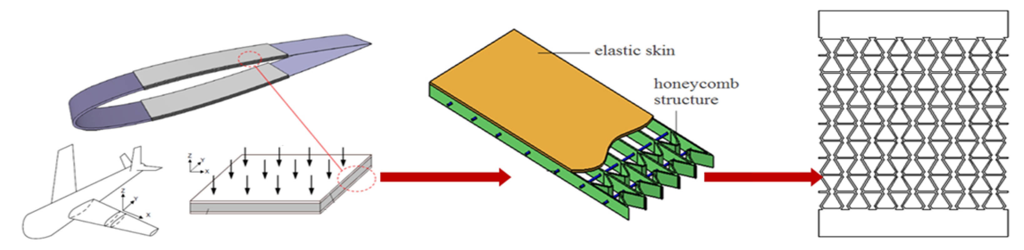
1. Introduction
2. Introduction to Honeycomb Structure
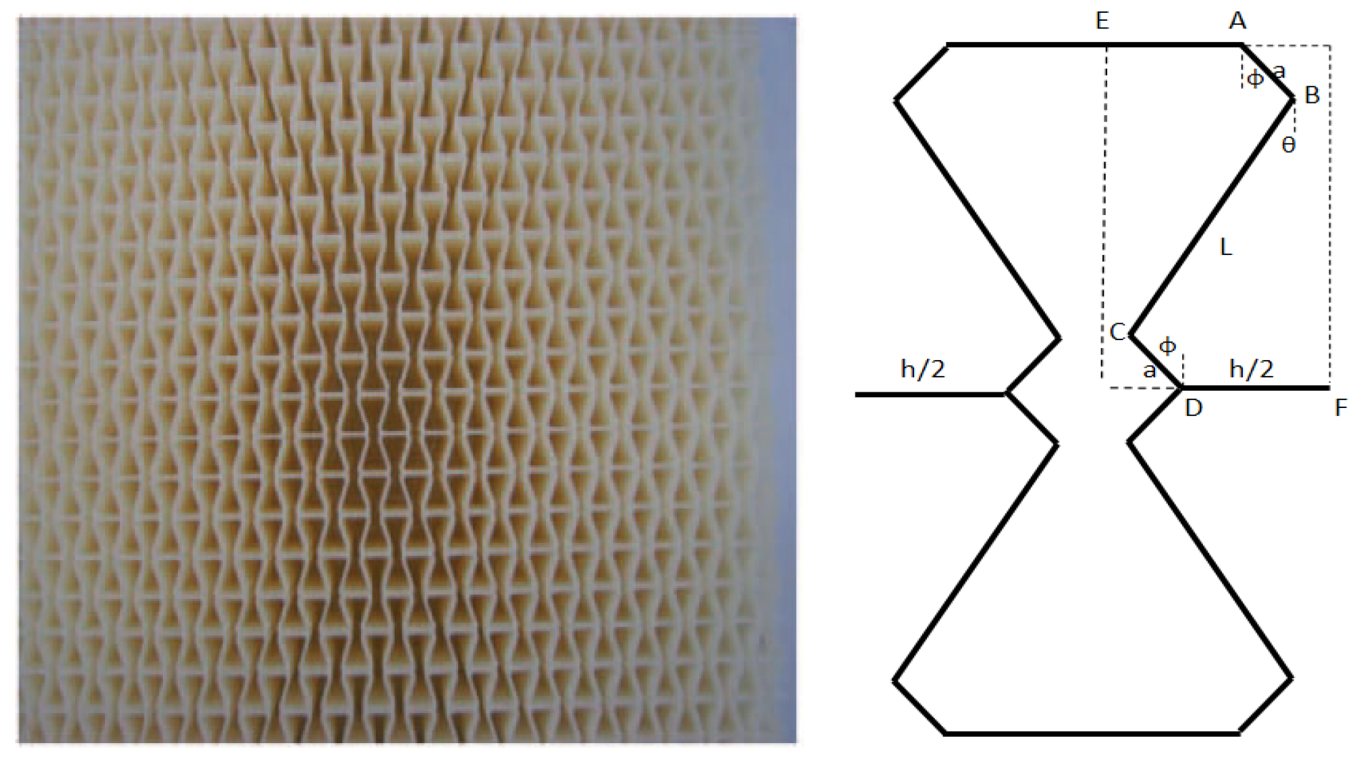
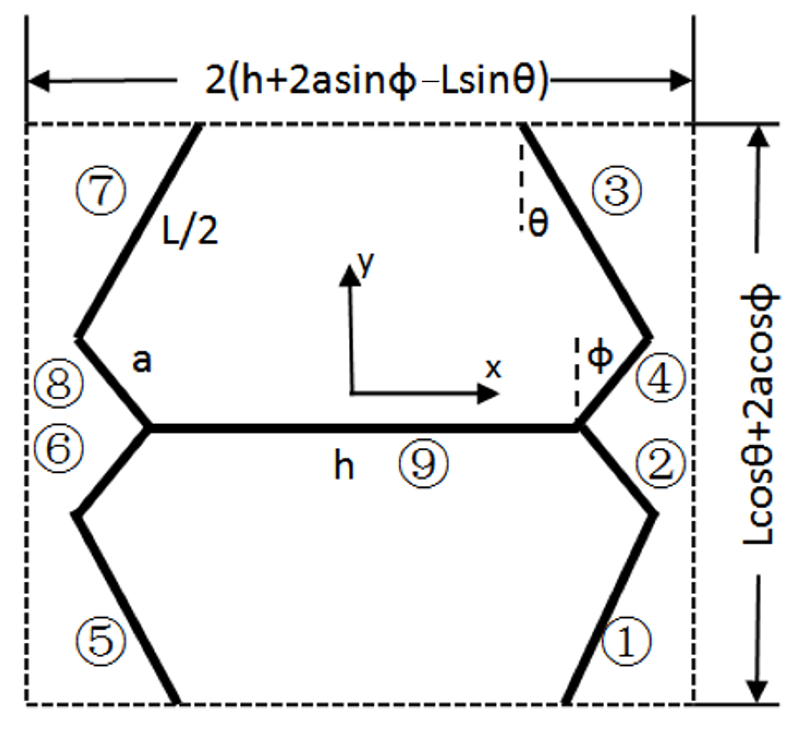
2.1. Geometric Parameters
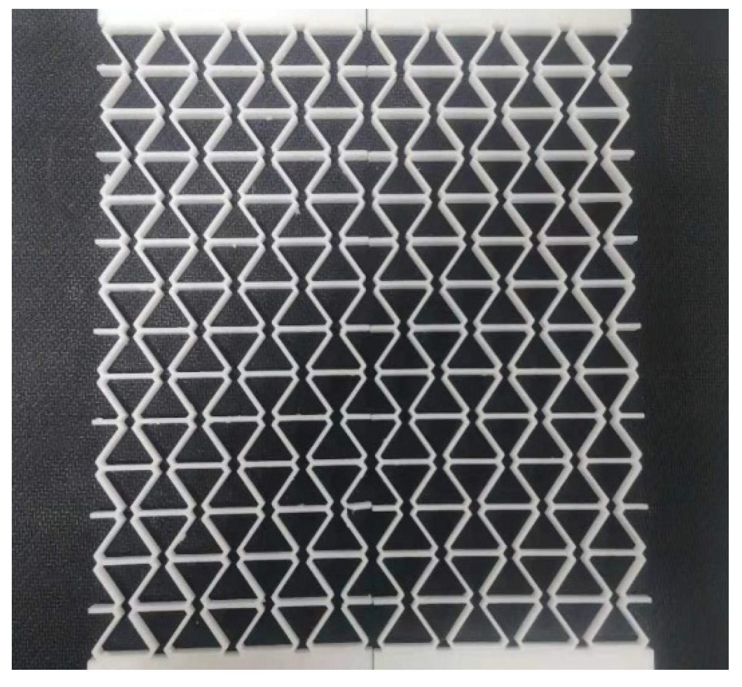
2.2. Specimen
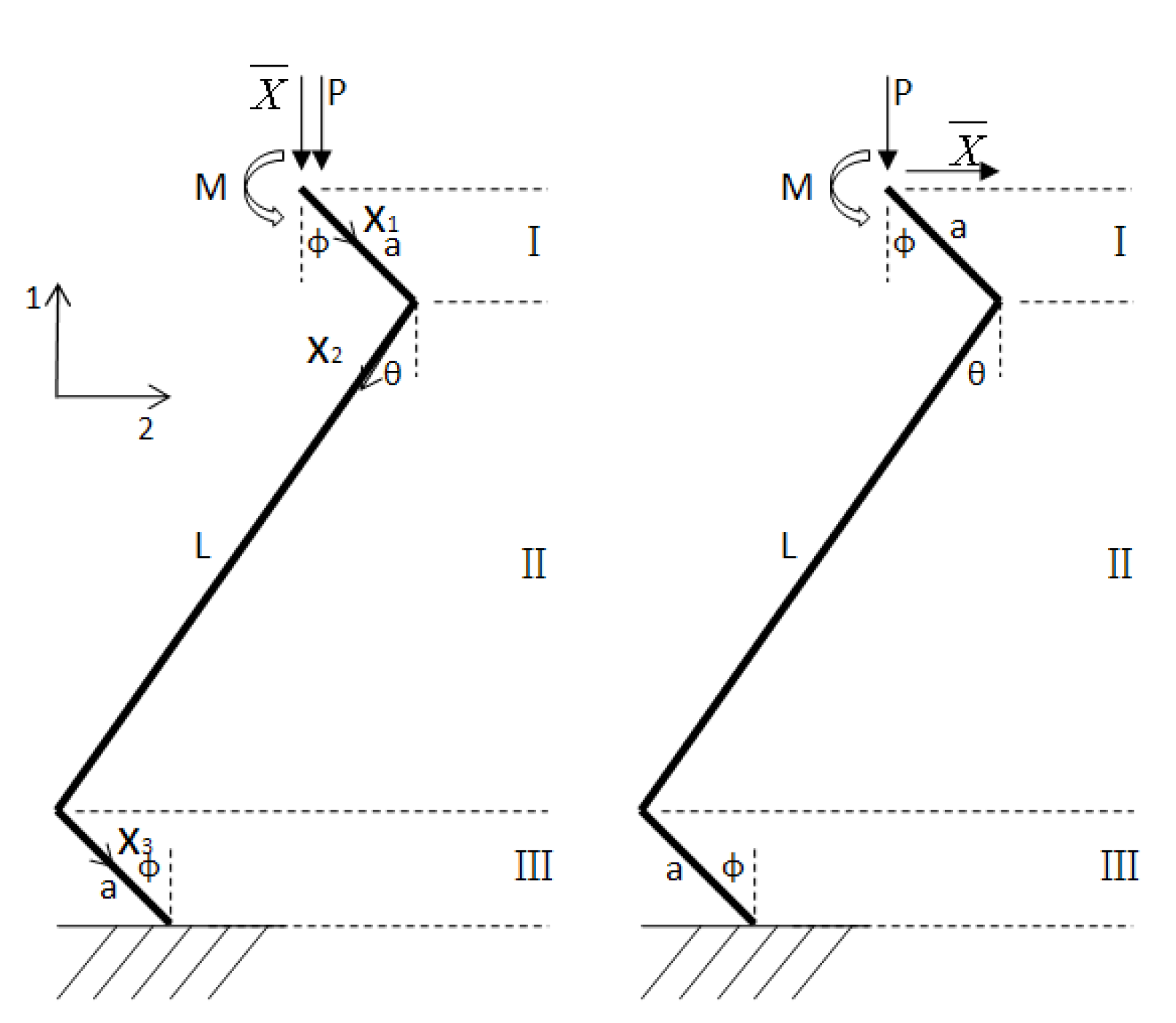
3. Theoretical Analysis of Mechanical Properties
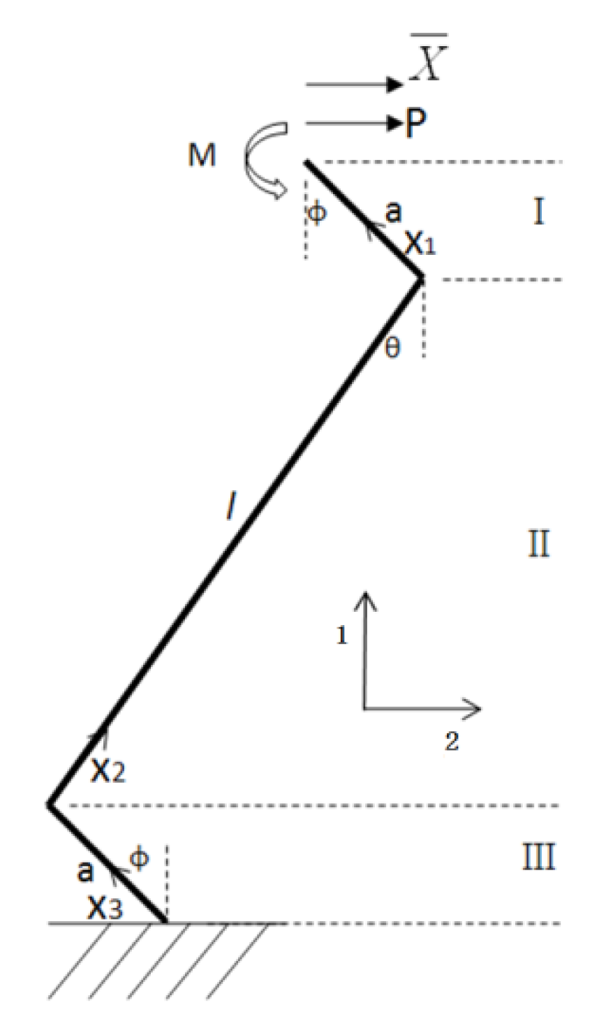
3.1. Equivalent Elastic Modulus
3.2. Equivalent Shear Modulus
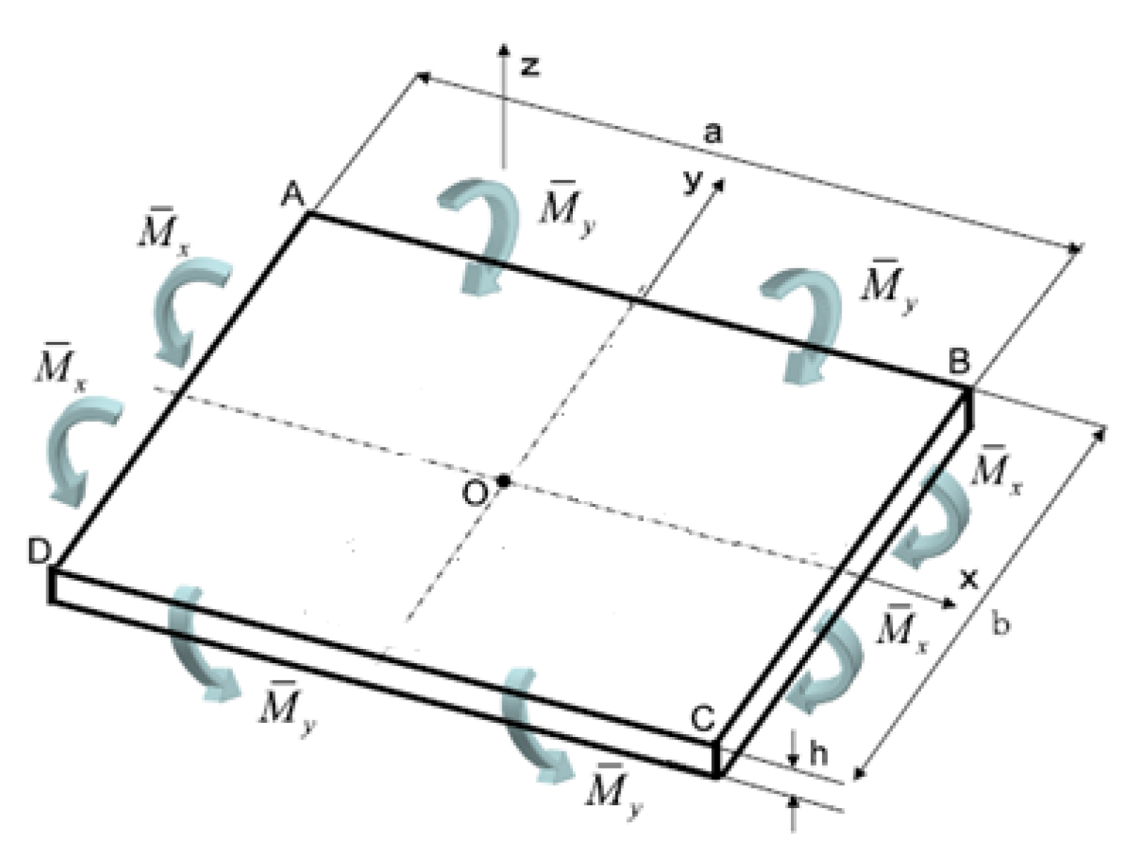
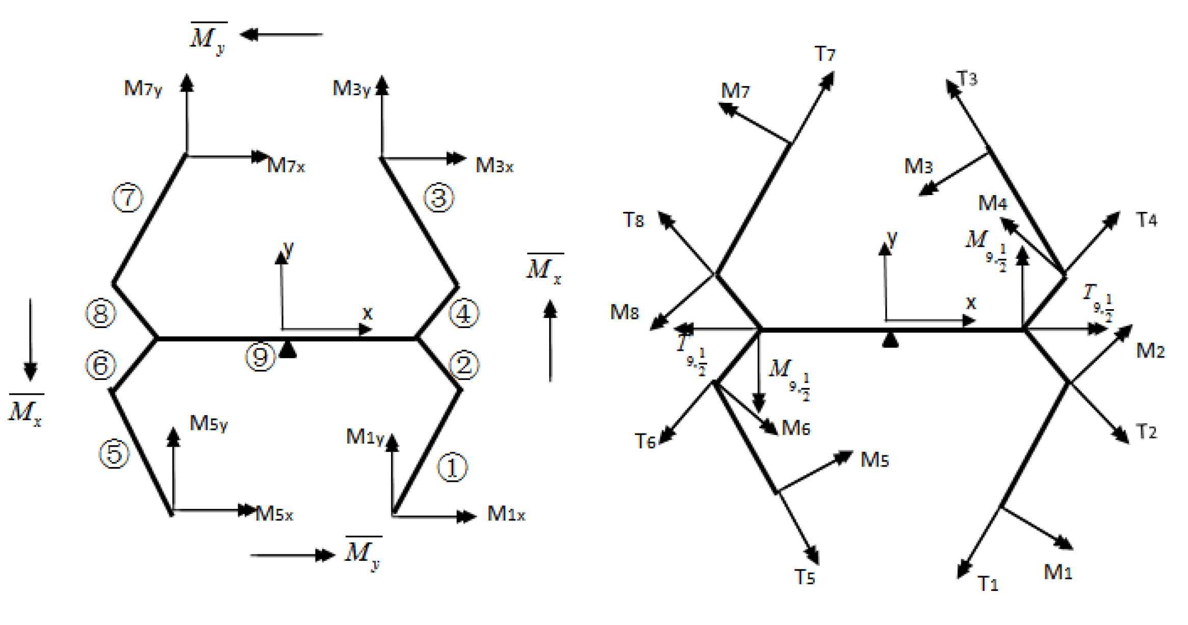
3.3. Equivalent Bending Stiffness
4. Mechanical Properties Testing
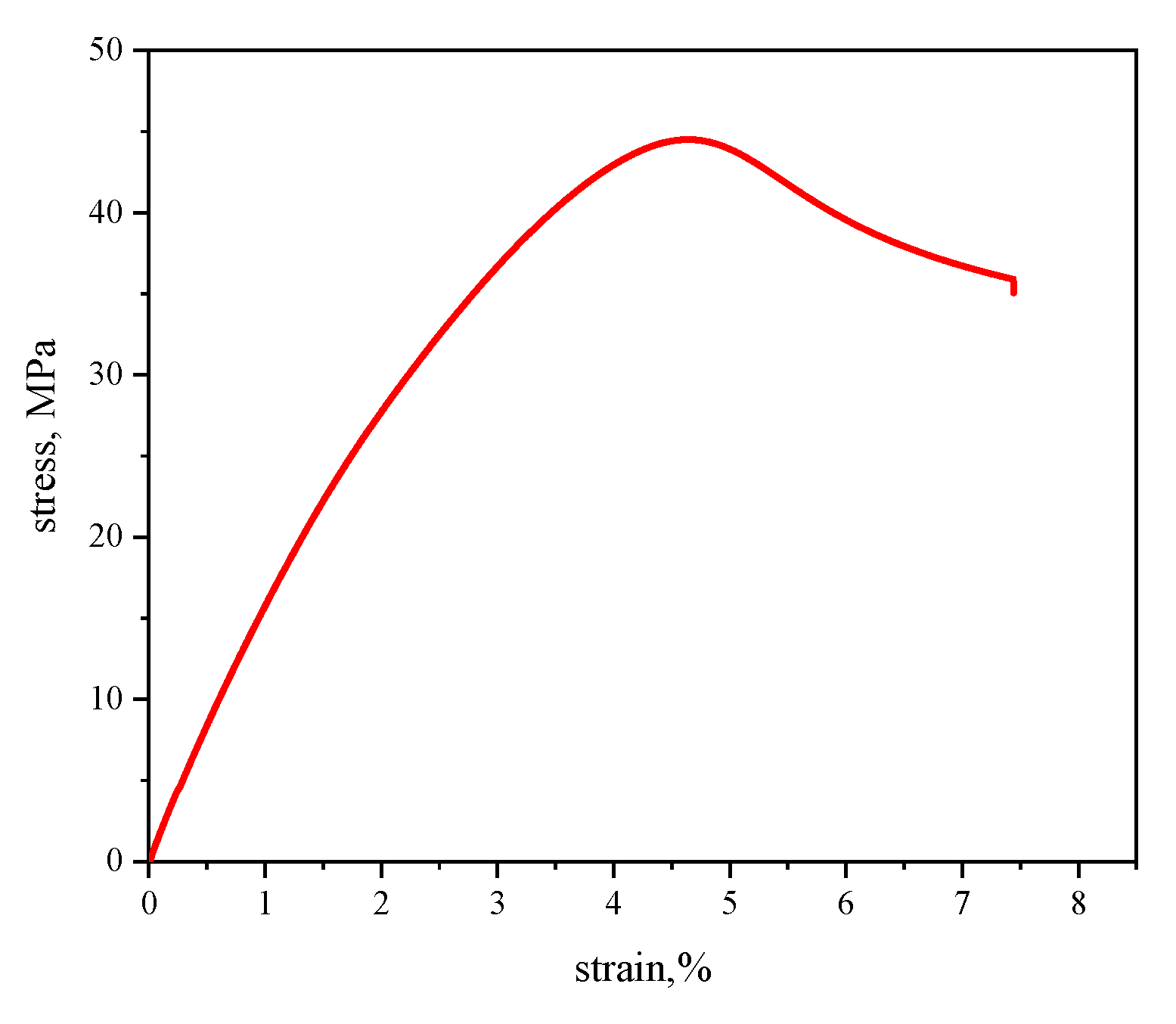
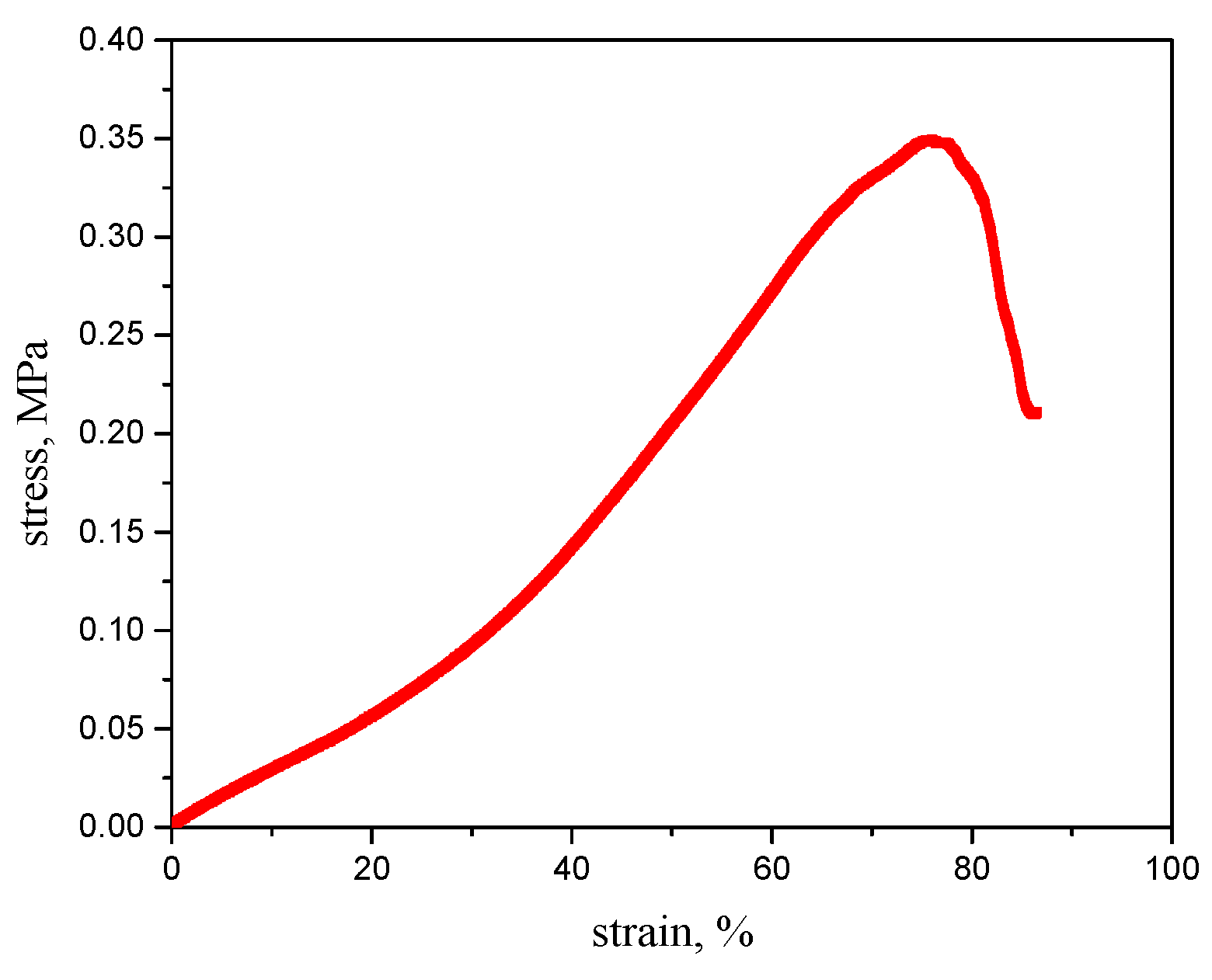
4.1. Material Properties Testing
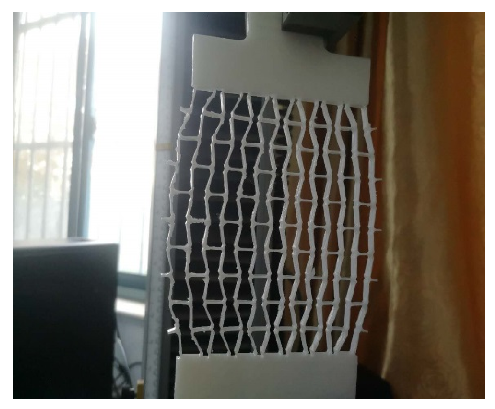
4.2. Elastic Modulus Testing of Honeycomb Structure
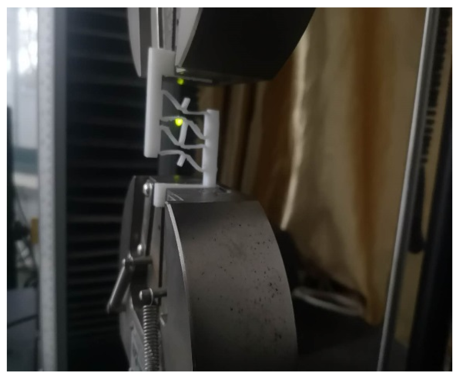
4.3. Shear Modulus Testing of Honeycomb Structure
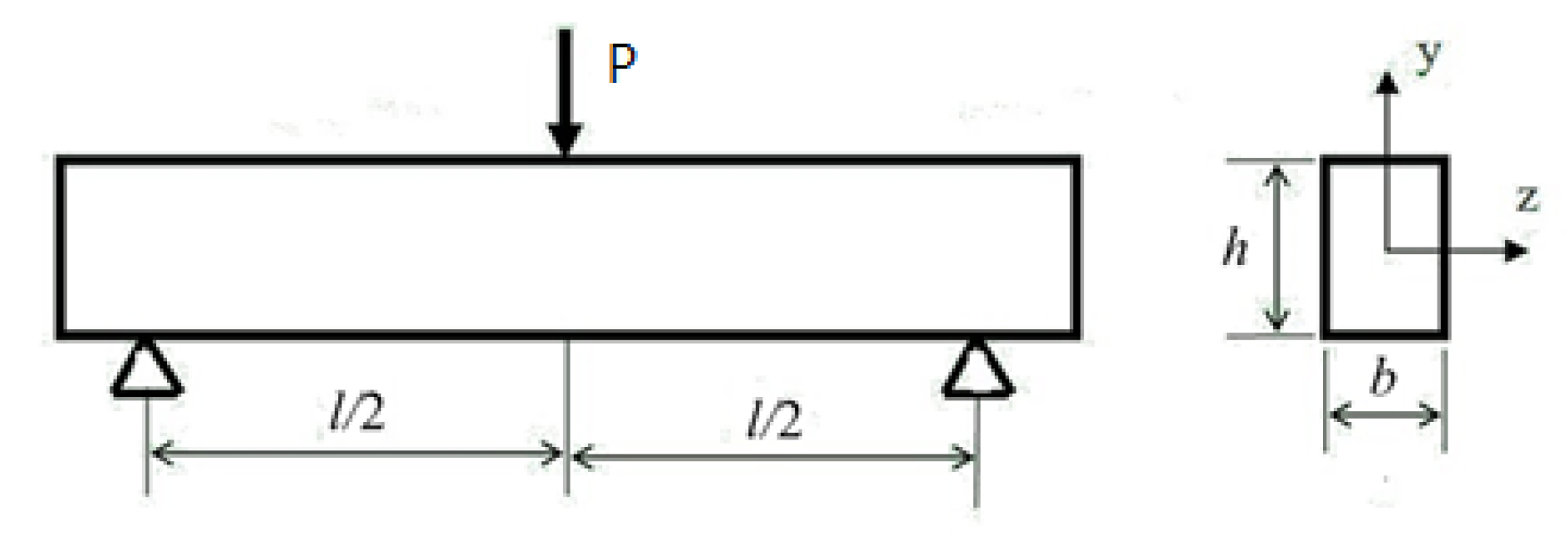
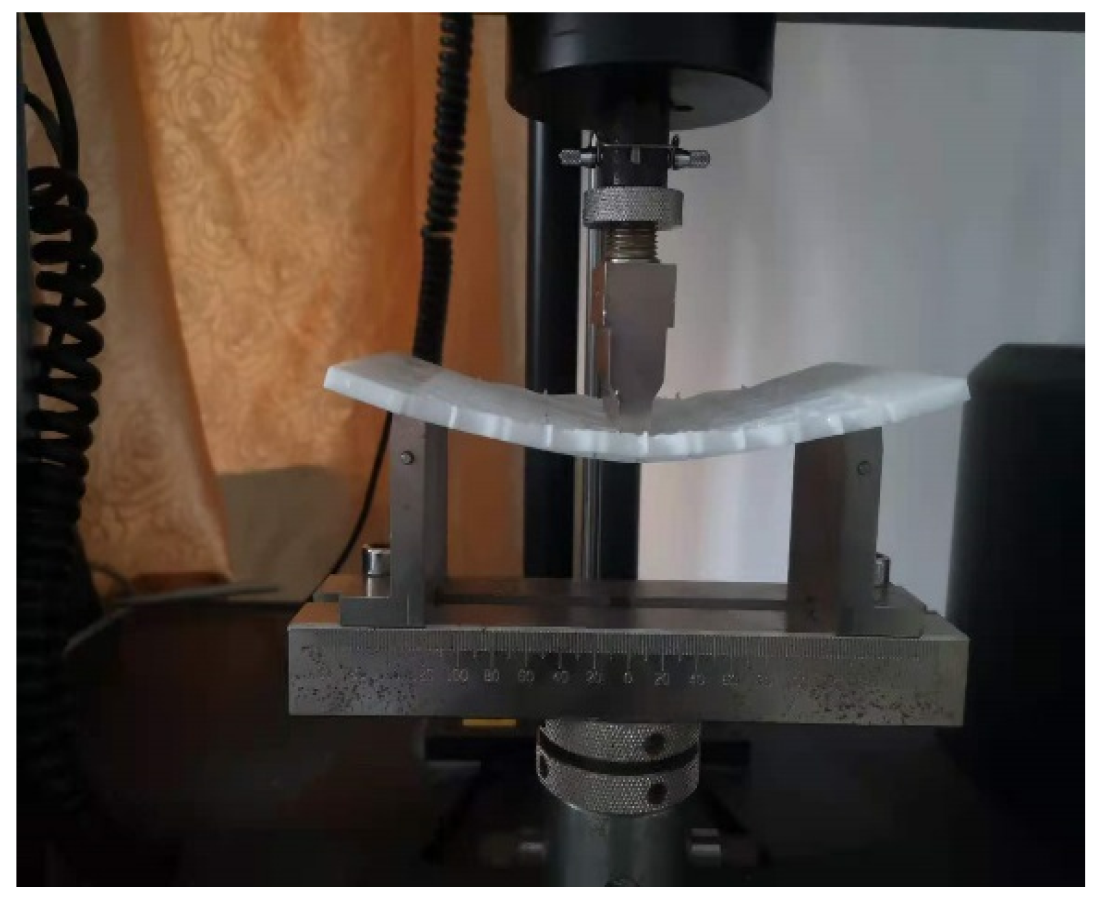
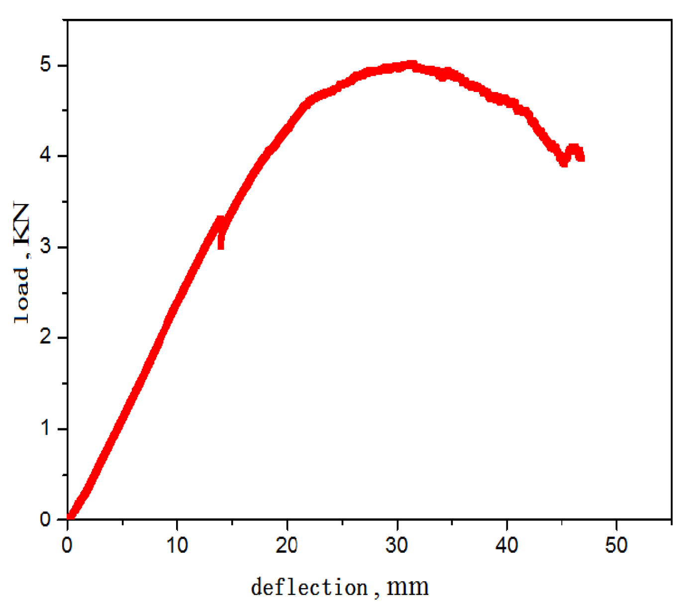
4.4. Bending Modulus Testing of Honeycomb Structure
5. Discussion & Conclusions
- (1)
- The theoretical method for calculating the elastic modulus of the honeycomb structure is based on the small deformation assumption and assumes that all structures are in a linear elastic deformation state, not considering material and geometric nonlinear effects.
- (2)
- Photosensitive materials are not linear elastic materials, and there is a certain error in the elastic modulus obtained from their stress–strain curves.
- (3)
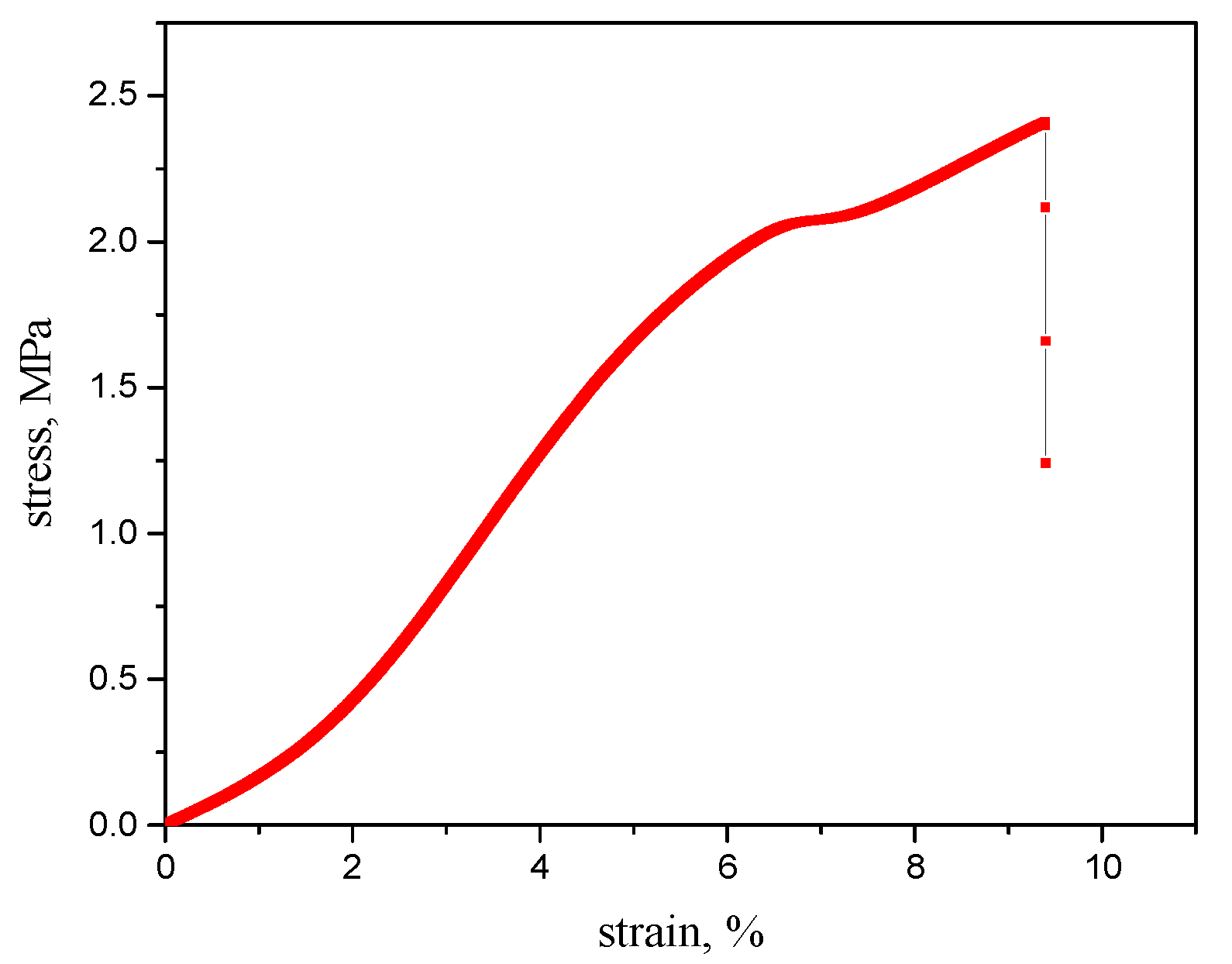
- The stress–strain or load-deflection curves from the tests exhibit significant nonlinear effects. Using only the approximate linear segment for calculating the equivalent elastic modulus introduces some error.
- (4)
- The number of test specimens in this experiment was relatively small, resulting in some uncertainty in the results.
- (5)
- In summary, the above are the reasons for the discrepancy between the theoretical and experimental values, and further research can be conducted to address this issue.
Author Contributions
Funding
Data Availability Statement
Conflicts of Interest
References
- Weisshaar, T.A. Morphing Aircraft Systems: Historical Perspectives and Future Challenges. J. Aircr. 2013, 50, 337–353. [Google Scholar] [CrossRef]
- Sofla, A.; Meguid, S.; Tan, K.; Yeo, W. Shape morphing of aircraft wing: Status and challenges. Mater. Des. 2010, 31, 1284–1292. [Google Scholar] [CrossRef]
- Joshi, S.; Tidwell, Z.; Crossley, W.; Ramakrishnan, S. Comparison of morphing wing strategies based upon aircraft performance impacts. In Proceedings of the 45th AIAA/ASME/ASCE/AHS/ASC Structures, Structural Dynamics and Materials Conference; Palm Springs, CA, USA, 19–22 April 2004; Volume 1722, pp. 1–7. [Google Scholar]
- Jha, A.K.; Kudva, J.N. Morphing aircraft concepts, classifications, and challenges. In Anderson E H, Proc. SPIE 5388, Smart Structures and Materials 2004: Industrial and Commercial Applications of Smart Structures Technologies; International Society for Optics and Photonics: San Diego, CA, USA, 2004; pp. 213–224. [Google Scholar]
- Olympio, K.R.; Gandhi, F. Flexible skins for morphing aircraft using cellular honeycomb cores. J. Intell. Mater. Syst. Struct. 2010, 21, 1719–1735. [Google Scholar] [CrossRef]
- Olympio, K.R.; Gandhi, F. Zero Poisson’s ratio cellular honeycombs for flex skins undergoing one-dimensional morphing. J. Intell. Mater. Syst. Struct. 2010, 21, 1737–1753. [Google Scholar] [CrossRef]
- Bubert, E.A.; Woods, B.K.; Lee, K.; Kothera, C.S.; Wereley, N. Design and Fabrication of a Passive 1D Morphing Aircraft Skin. J. Intell. Mater. Syst. Struct. 2010, 21, 1699–1717. [Google Scholar] [CrossRef]
- Ai, Q.; Weaver, P.M.; Azarpeyvand, M. Design and mechanical testing of a variable stiffness morphing trailing edge flap. J. Intell. Mater. Syst. Struct. 2018, 29, 669–683. [Google Scholar] [CrossRef]
- Naghavi Zadeh, M.; Dayyani, I.; Yasaee, M. Fish Cells, a new zero Poisson’s ratio metamaterial—Part I: Design and experiment. J. Intell. Mater. Syst. Struct. 2020, 31, 1617–1637. [Google Scholar] [CrossRef]
- Zadeh, M.N.; Dayyani, I.; Yasaee, M. Fish Cells, a new zero Poisson’s ratio metamaterial—Part II: Elastic properties. J. Intell. Mater. Syst. Struct. 2020, 31, 2196–2210. [Google Scholar] [CrossRef]
- Alderson, A.; Alderson, K.L.; Attard, D.; Evans, K.E.; Gatt, R.; Grima, J.N.; Miller, W.; Ravirala, N.; Smith, C.W.; Smith, C.W. Elastic constants of 3-, 4-and 6-connected chiral and anti-chiral honeycombs subject to uniaxial in-plane loading. Compos. Sci. Technol. 2010, 70, 1042–1048. [Google Scholar] [CrossRef]
- Theocaris, P.S.; Stavroulakis, G.E.; Panagiotopoulos, P.D. Negative Poisson’s ratios in composites with star-shaped inclusions: A numerical homogenization approach. Arch. Ofapplied Mech. 1997, 67, 274–286. [Google Scholar] [CrossRef]
- Larsen, U.D.; Signund, O.; Bouwsta, S. Design and fabrication of compliant micromechanisms and structures with negative Poisson’s ratio. J. Micro Electromechanical Syst. 1997, 6, 99–106. [Google Scholar] [CrossRef]
- Bezazi, A.; Remillat, C. In-plane mechanical and thermal conductivity properties of a rectangular–hexagonal honeycomb structure. Compos. Struct. 2008, 84, 248–255. [Google Scholar] [CrossRef]
- Bezazi, A.; Scarpa, F.; Remillat, C. A novel centresymmetric honeycomb composite structure. Compos. Struct. 2005, 71, 356–364. [Google Scholar] [CrossRef]
- Dong, W.; Sun, Q. Equivalent elastic modulus analysis of accordion cellular material. Mech. Sci. Technol. Aerosapace Eng. 2011, 18, 1103–1106. (In Chinese) [Google Scholar]
- Guo, Y.; Wang, L.; Wu, C.; Duan, S. A study on in-plane equivalent elastic parameters of complex polygonal honeycomb Core. J. Mech. Strength 2016, 38, 1258–1263. (In Chinese) [Google Scholar]
- Guo, Y.; Wang, L.; Duan, S. A study on equivalent flexural rigidity of complex polygonal honeycomb structure. J. Mech. Strength 2017, 39, 122–129. (In Chinese) [Google Scholar]
- Chen, D.H. Equivalent flexural and torsional rigidity of hexagonal honeycomb. Compos. Struct. 2011, 93, 1910–1917. [Google Scholar] [CrossRef]
Disclaimer/Publisher’s Note: The statements, opinions and data contained in all publications are solely those of the individual author(s) and contributor(s) and not of MDPI and/or the editor(s). MDPI and/or the editor(s) disclaim responsibility for any injury to people or property resulting from any ideas, methods, instructions or products referred to in the content. |
© 2024 by the authors. Licensee MDPI, Basel, Switzerland. This article is an open access article distributed under the terms and conditions of the Creative Commons Attribution (CC BY) license (https://creativecommons.org/licenses/by/4.0/).
Share and Cite
Guo, Y.; Wang, L.; Ai, S.; Chang, L.; Nie, X. Theoretical Study and Verification of the Mechanical Properties of Concave Honeycomb Structures Based on Additive Manufacturing. Eng. Proc. 2024, 80, 5. https://doi.org/10.3390/engproc2024080005
Guo Y, Wang L, Ai S, Chang L, Nie X. Theoretical Study and Verification of the Mechanical Properties of Concave Honeycomb Structures Based on Additive Manufacturing. Engineering Proceedings. 2024; 80(1):5. https://doi.org/10.3390/engproc2024080005
Chicago/Turabian StyleGuo, Yuchao, Likai Wang, Sen Ai, Liang Chang, and Xiaohua Nie. 2024. "Theoretical Study and Verification of the Mechanical Properties of Concave Honeycomb Structures Based on Additive Manufacturing" Engineering Proceedings 80, no. 1: 5. https://doi.org/10.3390/engproc2024080005
APA StyleGuo, Y., Wang, L., Ai, S., Chang, L., & Nie, X. (2024). Theoretical Study and Verification of the Mechanical Properties of Concave Honeycomb Structures Based on Additive Manufacturing. Engineering Proceedings, 80(1), 5. https://doi.org/10.3390/engproc2024080005