Proceeding Paper

Design Optimization and Testing of Seamless Morphing Leading Edge for Large Civil Aircraft †

1
National Key Laboratory of Strength and Structural Integrity, Aircraft Strength Research Institute of China, Xi’an 710065, China
2
School of Aeronautics and Astronautics, Shanghai Jiao Tong University, Shanghai 200240, China
3
School of Aeronautical Science and Engineering, Beihang University, Beijing 100191, China
*
Author to whom correspondence should be addressed.
Presented at the 2nd International Conference on Green Aviation (ICGA 2024), Chengdu, China, 6–8 November 2024.
Eng. Proc. 2024, 80(1), 49; https://doi.org/10.3390/engproc2024080049
Published: 30 May 2025
(This article belongs to the Proceedings of 2nd International Conference on Green Aviation (ICGA 2024))

Abstract

Climate change has prompted the aviation industry to decrease its emissions of greenhouse gases. With their aerodynamic shape adaptability, morphing leading edges have great potential in the application of laminar flow wings and are beneficial to green aviation. As most of the current morphing leading edges are still in laboratory demonstrations, this paper develops a three-dimensional full-scale morphing leading edge physical prototype for a large-scale civil aircraft and demonstrates its feasibility through a ground and wind tunnel test. The final test results show that the developed morphing leading edge can be morphed into its target shape smoothly and precisely, and validate the effectiveness of the design approach.

1. Introduction

Human activities, principally through emissions of greenhouse gases, have unequivocally caused global warming, with the global surface temperature reaching 1.1 °C above that in 1850–1900 in 2011–2020, which is already affecting many weather and climate extremes in every region across the globe [1]. Therefore, all sectors are engaging in efforts to decrease emissions to achieve the 1.5 °C and 2 °C temperature goals of the Paris Agreement. According to the Waypoint 2050 report of the Air Transport Action Group (ATAG) released in 2021, the aviation sector needs to achieve net zero carbon emissions by 2050, and advancing aircraft technologies can account for 34% of emission reduction contributions by 2050 in a scenario with aggressive technology developments. One type of these innovation technologies is local-geometry-improving technologies such as improved laminar flow control and morphing wings and wingtip devices [2].
With the ability to adapt aerodynamic shapes seamlessly and smoothly to different flight conditions, morphing leading edges are one kind of important green aviation technology. The first advantage of them is the potential to achieve a larger-scale laminar flow area on a laminar wing as they do not provide any steps towards the wing boxes on the upper (different to the Krueger device) or the lower surface [3]. The second is that they can improve aerodynamic efficiency by working together with morphing trailing edges in cruising cases [4]. Additionally, smooth morphing leading edges are beneficial to decreasing noise in take-off and landing cases [5].
To this end, lots of morphing leading edge concepts have been developed in recent years, as shown in the literature [6,7,8,9,10]. Most of these concepts can be divided into two categories: compliant and rigid–flexible coupling. For the rigid–flexible coupling type [6,7,8,9,10], it is easier to balance the design contradictions between a high load-bearing capacity and a large morphing capacity, making this type the mainstream choice of morphing leading edge for large civil aircraft. Moreover, rigid–flexible coupling morphing leading edges can be further divided into open-chain and close-chain types based on their inner kinematic mechanism types. With direct connections to the outer compliant skins, morphing leading edges with an open-chain mechanism are simpler and have advantages in the aspects of weight and reliability. However, most of the current research on this kind of morphing leading edge remains in the concept or laboratory stage, which limits the improvement of the technology readiness level.
To this end, this paper develops a design approach for a morphing leading edge based on an open-chain kinematic mechanism and manufactures a full-scale physical prototype for a large civil aircraft with the support of a National Research Project titled “Variable Camber Wing Technology (VCAN)”. In this paper, Section 2 presents the design approach for the outer compliant skin. Then, the inner kinematic mechanism design approach is illustrated in Section 3. The three-dimensional design, manufacturing, and testing are presented in Section 4. Finally, some conclusions and future prospects are given in Section 5.

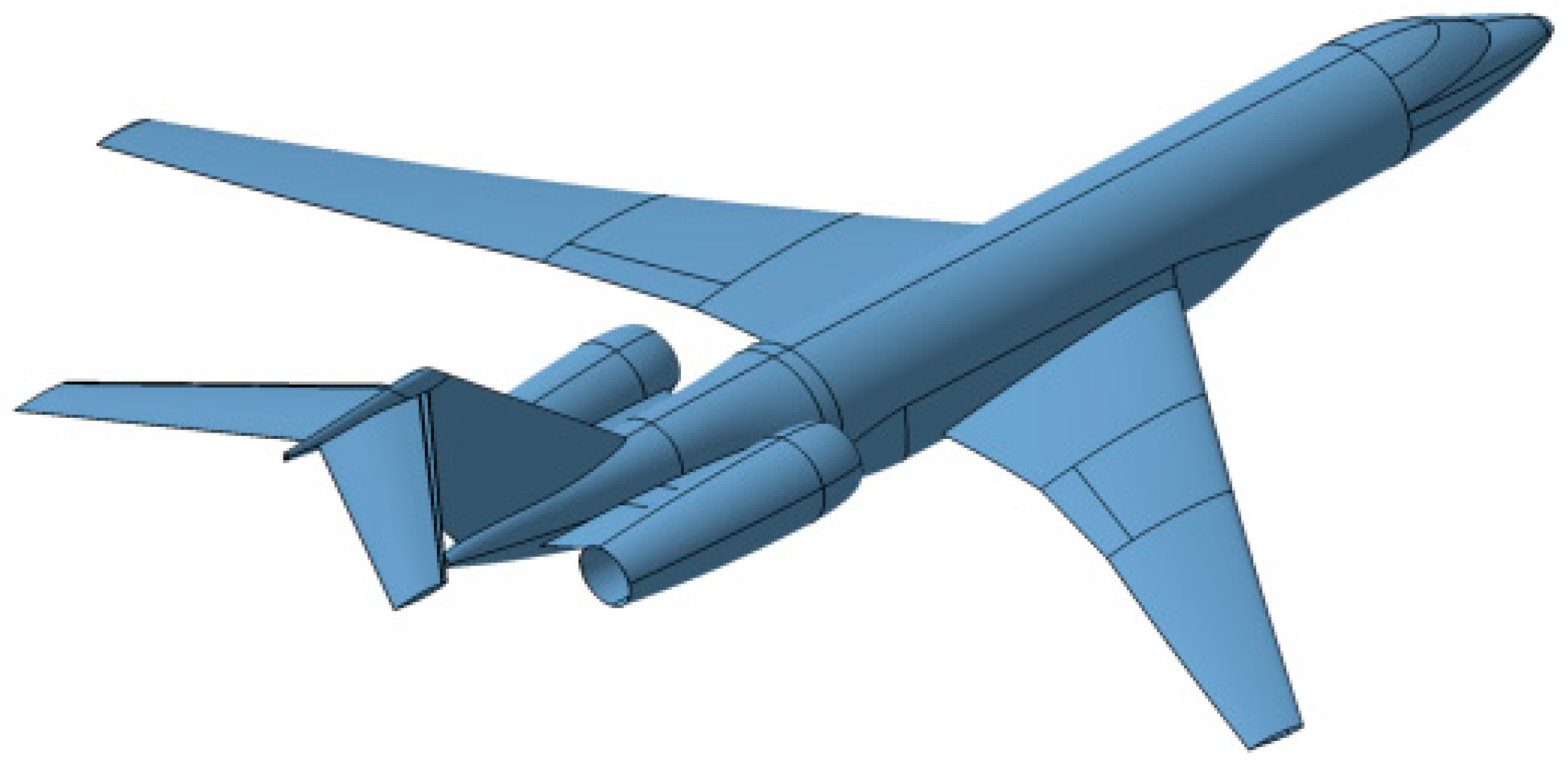
2. Reference Aircraft and Structural Concept

Before the design of the compliant skin and kinematic mechanism, the first thing is to determine some design inputs such as the geometry and aerodynamic load-bearing requirements. In the VCAN program, a morphing wing with adaptive leading and trailing edges is proposed for use on a long-haul business jet cruising at Mach 0.87 [11]. The design features a low-mounted, backswept wing with a high aspect ratio, two engines mounted at the rear fuselage, and a T-tail, as illustrated in Figure 1. For simplifying the problem, a profile located at 30% span length from the fuselage is utilized as the design profile.
For transport aircraft, cruising is the most common flight condition. Therefore, it is reasonable to define the optimal aerodynamic surface for cruising as the initial profile. This approach simplifies the actuation system and reduces power requirements, as the system can maintain the cruise configuration using a simple mechanical self-locking device in practical engineering applications. In contrast, the optimal aerodynamic surface for take-off or landing—though less frequently used—is the most deflected configuration, requiring the highest actuation power. As such, this configuration is defined as the target profile.
In the project, the optimal initial aerodynamic profile is provided by Hua et al., specifically in reference [11,12]. For the selected aircraft, a two-dimensional drooped profile with a deflection angle of 20 degrees and a leading edge radius of 16 mm is used as the target profile because the corresponding maximum lift coefficient is sufficient for take-off, as shown in Figure 2.
As illustrated previously, rigid–flexible coupling is preferred for large civil aircraft. The rigid–flexible coupling concept utilized in this paper is shown in Figure 3. ‘Rigid’ refers to the inner open-chain actuating mechanism, and ‘compliant’ refers to the outer variable-stiffness compliant skin. Here, as a simplified schematic diagram, the open chain is represented with only one single crank and one connecting rod. In practical cases, there can be more cranks and connecting rods, or one single crank with several connecting rods. More cranks mean more actuators and a higher weight. In addition, with a variable stiffness distribution along the circumferential direction, the compliant skin’s deforming ability can be adapted exactly to the target profile if the number of connecting rods and the mechanism layout are appropriately designed. Therefore, both the outer compliant skin and inner kinematic mechanism need to be carefully optimized. To further enhance the deflecting capacity of the compliant skin, one kind of aviation-class glass-fiber-reinforced polymer (Guangwei Ltd.) is utilized. Its mechanical properties are shown in Table 1.

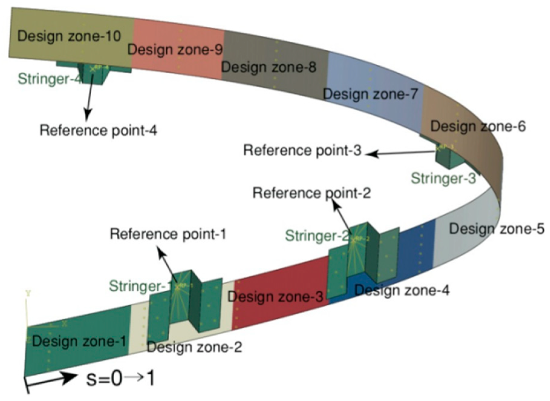
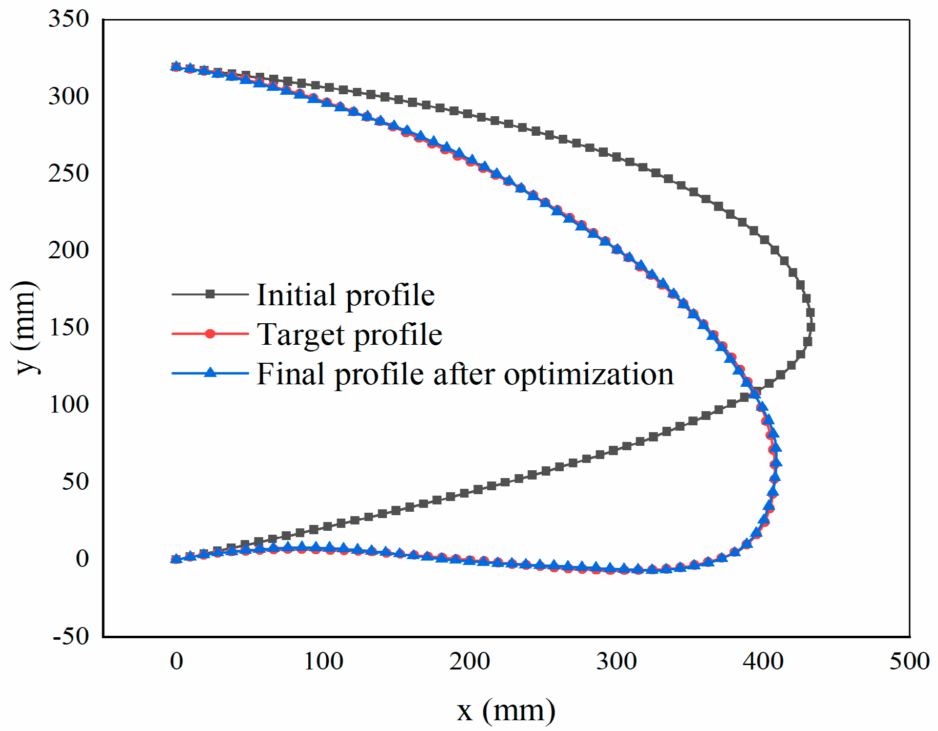
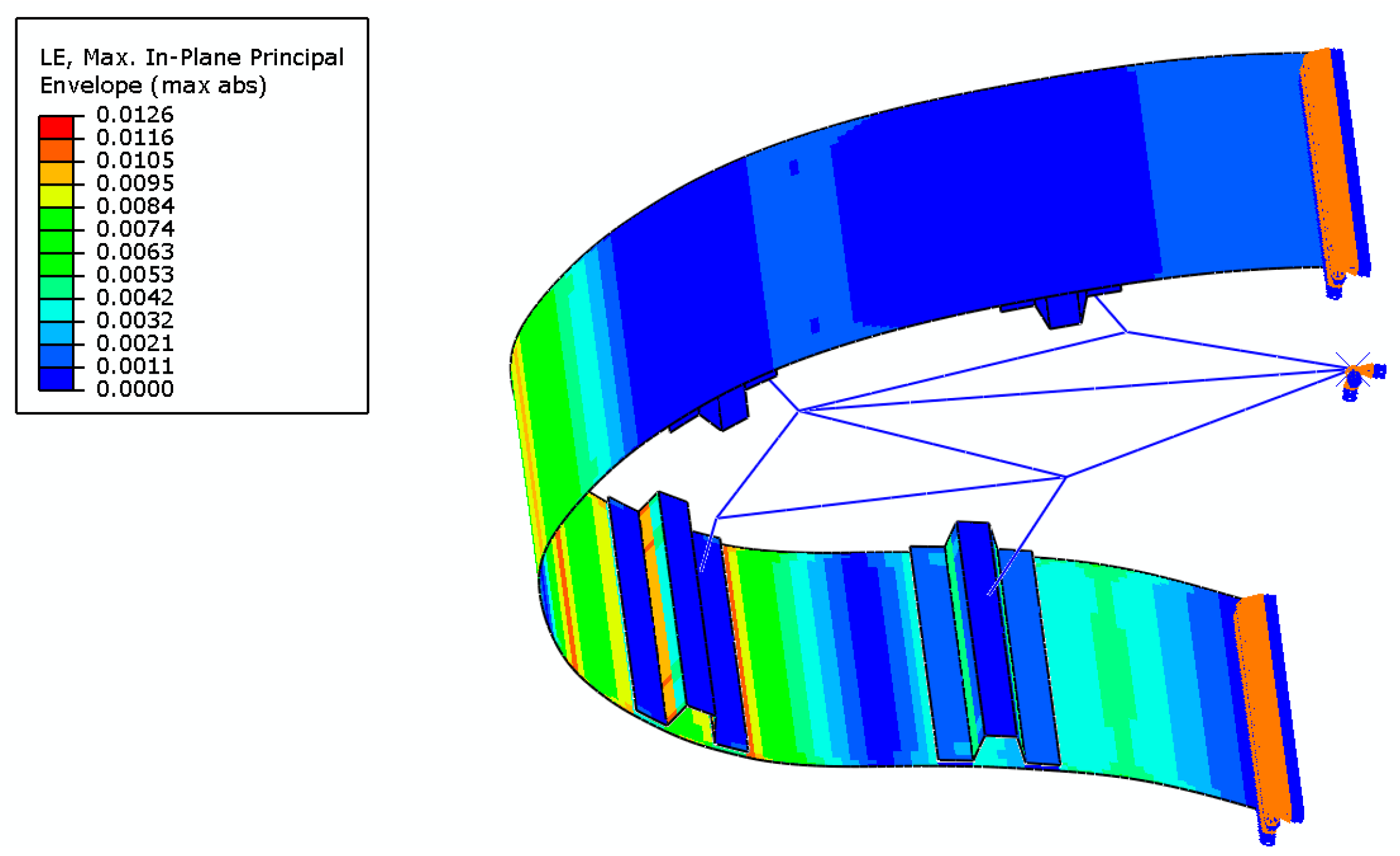
3. Design Approach of Variable-Thickness Compliant Skin

In order to improve the deforming precision of the morphing leading edge, having as many connecting rods as possible is best, but this will require a more complex driving system and mechanism system. Balancing these two factors, this paper arranges only four connecting rods to deflect the compliant skin to the target aerodynamic profile, represented by four connecting stringers, as shown in Figure 4. In addition, the compliant skin is sectioned into 10 thickness zones to model a variable stiffness distribution. The most important thing for the compliant skin is to determine the specific stacking sequence of the composite layups in different thickness regions, the positions of the four stringers along the circumferential direction, and the transferred forces exacted by the four connecting rods on the four stringer hats. To this end, an optimization formula is established to examine the optimal values of these three types of design variables.
In order to describe the actual stacking sequence of the layups in different thickness regions, a fiber continuity model is utilized here based on a drop-off sequence, a guiding sequence, and a thickness sequence. The available thickness values for them are the multiples of a true layer thickness of 0.001 mm. Finally, the mathematical formulation of the variable-stiffness compliant skin optimization problem is defined as Equation (1):
min           f ( s i , g j , d k , t m , f n ) = L S E = p = 1 q x p x p 2 + y p y p 2 q s . t .           K ( U ) U = F ( U )                       s i ( 0 , 1 ) ,   i = 1 , 2 , , 4 ;                       g j [ ± 75 ° , ± 45 ° , ± 30 ° , ± 15 ° , 0 ° , 90 ° ] ,   j = 1 , 2 , , M a x L a y e r N u m b e r ;                       d k [ 1 , 2 , , M a x L a y e r N u m b e r ] ,   k = 1 , 2 , , M a x L a y e r N u m b e r ;                       t m [ 1 , M a x L a y e r N u m b e r ] ,   m = 1 , 2 , , R e g i o n N u m ;                       f n [ L o w e r , U p p e r ] ,   n = 1 , 2 , , S t r i n g e r N u m ; ,
where   f ( s i , g j , d k , t m , f n ) is the objective or fitness function; ( x p , y p ) and ( x p , y p ) are the final and target point coordinates of the p-th element node, respectively; q is the number of element nodes along the circumferential direction of the compliant skin, and here it is 200; K ( U ) U = F ( U ) is the nonlinear equilibrium equation of the overall finite element model; s i is the i-th stringer’s position; g j is the j-th variable in the guiding sequence; d k is the k-th variable in the ply-drop sequence; t m is the m-th region’s thickness; and f n is the n-th component of the transmitted forces.
Conventional gradient-based optimizers are inadequate for the current problem, which requires collaborative optimization involving both continuous variables (e.g., actuating loads) and discrete variables (e.g., stiffness distribution over the flexible skin, composite layup sequence, and actuator positions). Moreover, these methods are prone to being trapped in local optima. In contrast, the second-generation Non-dominated Sorting Genetic Algorithm (NSGA-II) is recognized for its high efficiency and stability in global optimization tasks. At the outset, a population of design variables (individuals) is initialized. For each individual, the main procedure invokes the finite element (FE) module to generate a corresponding numerical model of the morphing leading edge. Each model is customized based on its respective design variables. These models are then analyzed to simulate the drooping deformation, and their performance is evaluated using the Least Squares Error (LSE) as a fitness function. Following evaluation, the main procedure updates the design variables through genetic operations such as selection, crossover, and mutation to produce a new generation (offspring). This optimization loop continues until the convergence criterion is met. As previously described, the compliant skin undergoes large deformations during the drooping process, introducing geometric nonlinearity. Specifically, the direction of aerodynamic forces in the structural FE model must be updated in real time to remain perpendicular to the deformed skin surface. To accommodate this, a nonlinear finite element analysis is employed instead of a linear one. This approach not only ensures more accurate deformation modeling but also yields the movement trajectories of actuating points along the stringers throughout the optimization process. Although computationally more intensive, this analysis provides crucial support for the subsequent design of the internal kinematic mechanism.
After 133 optimization iterations, a converged result is obtained. The final shape achieved is presented in Figure 5. The final LSE is 0.74 mm, which means the average distance deviation at all monitoring points from the target is 0.74 mm. This error is negligible compared with the overall size of the morphing leading edge (about 450 mm in chord length).

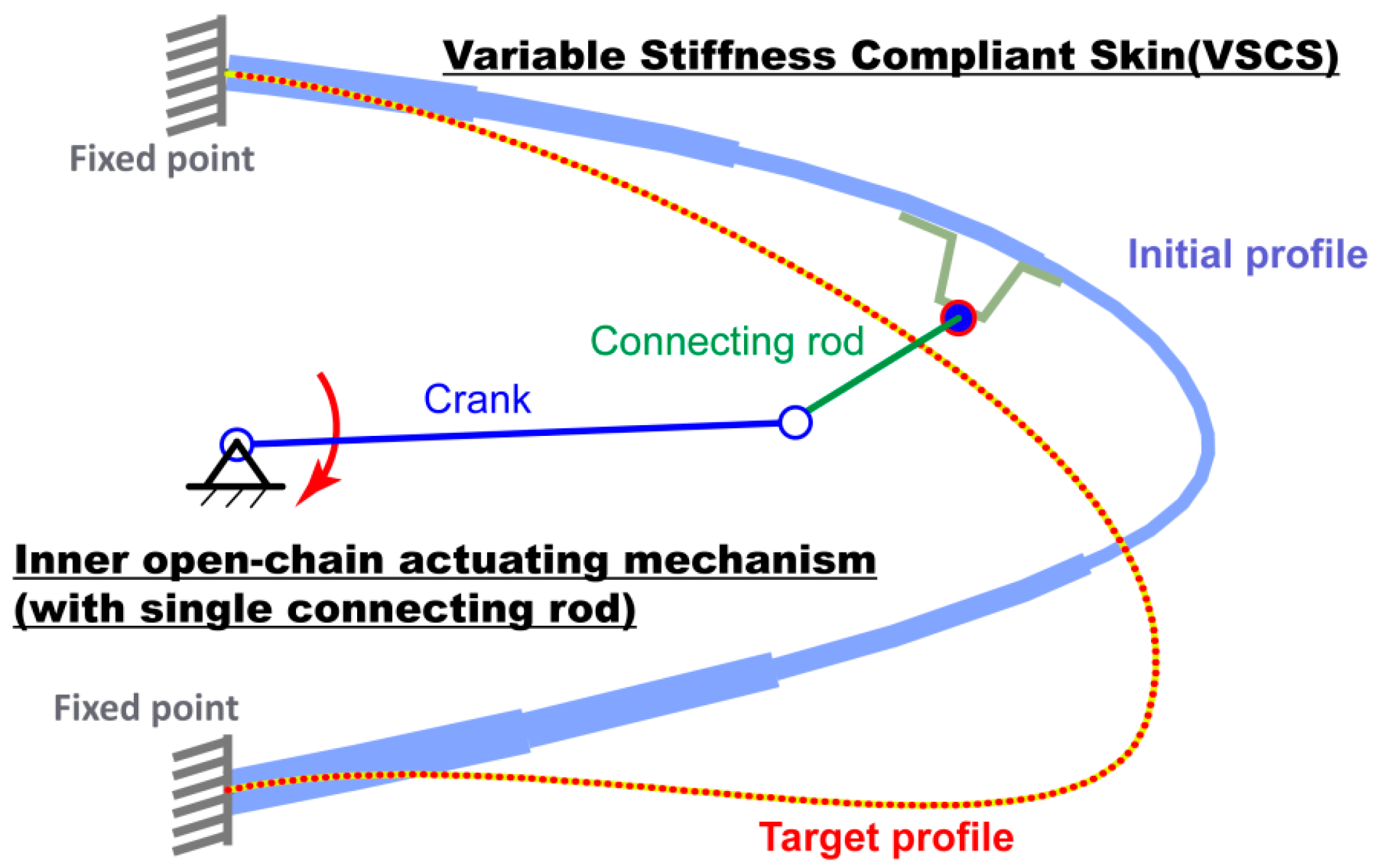
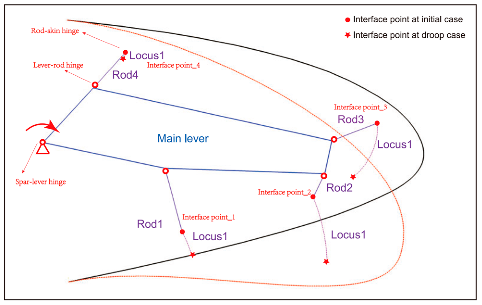
4. Design Approach of Inner Open-Chain Kinematic Mechanism

With the optimization result of the compliant skin, the moving locus of the interface points between the connecting rods and the stringers can be produced, and it can be used as the input of the design of the inner driving kinematic mechanism. To determine the specific layout of the mechanism, an initial configuration of the mechanism is predefined, as shown in Figure 6. It can be seen that one single main lever or crank is utilized to drive the other four connecting rods to deflect the compliant skin to the target profile. All connecting rods are connected to the crank and compliant skin directly, meaning there is a set of open-chain mechanisms, which can simplify the kinematic mechanism and decrease its weight and complexity.
With the predefined open-chain driving mechanism, an optimization approach is established to determine the optimal position of the interface points of the inner kinematic mechanism. In the optimization process, a multi-body dynamic finite element model is developed to model the drooping process of the morphing leading edge. Figure 7 presents the multi-body dynamic finite element model with the optimal layout of the inner kinematic mechanism. For the drooped configuration, the maximum deviation between the target coordinates and the final ones of the interface points on the stringers of the compliant skin is less than 2.0 mm.

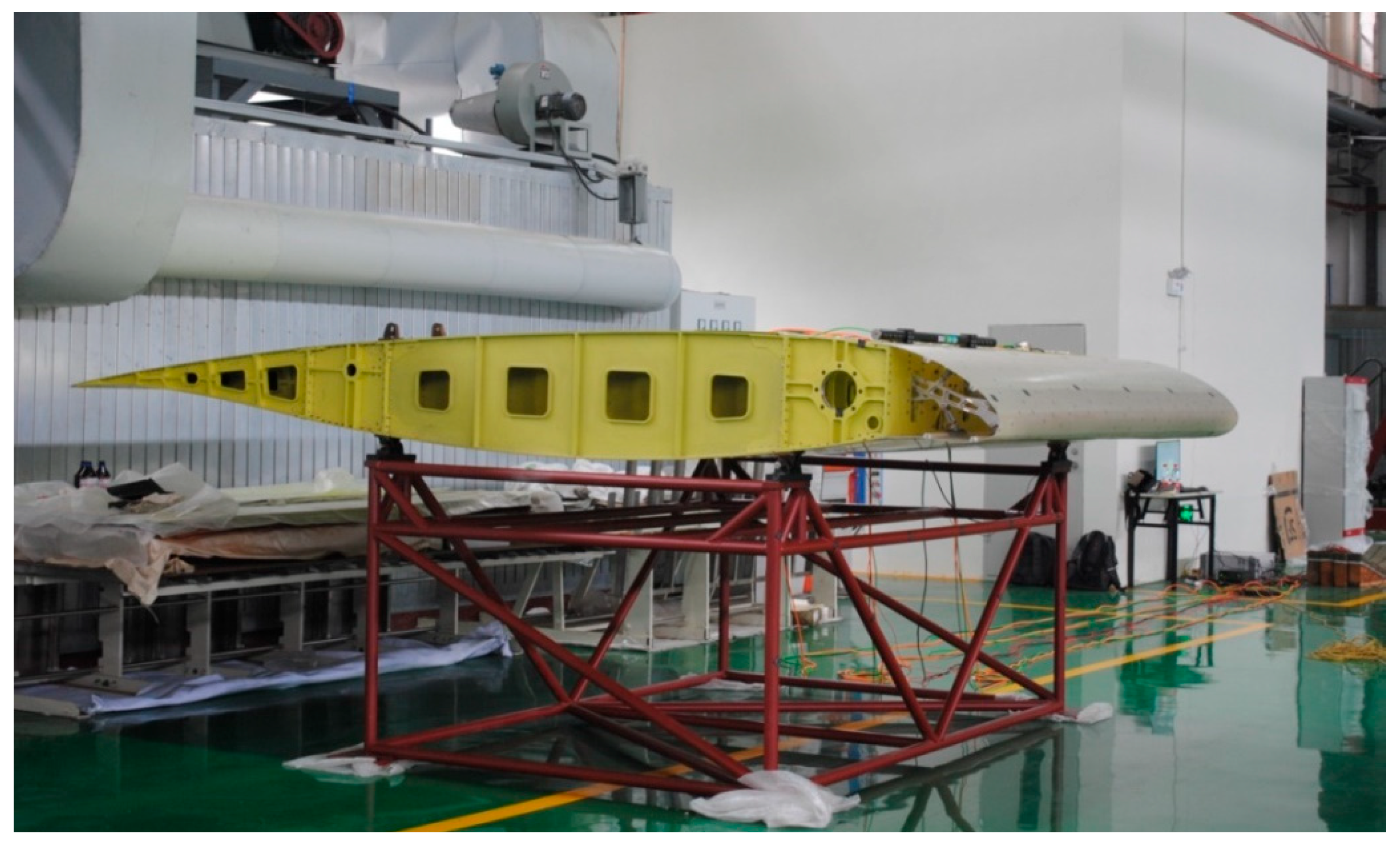
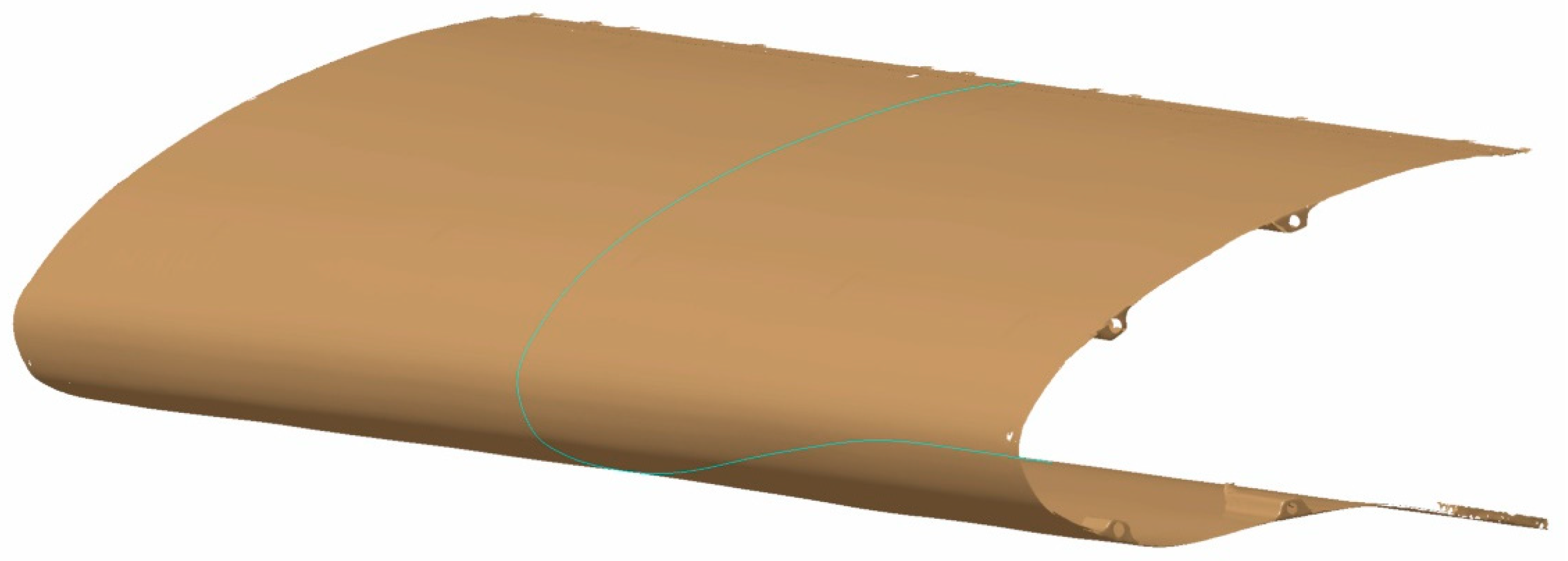
5. Manufacturing and Testing of Morphing Leading Edge

Based on the optimization of the outer compliant skin and the inner kinematic mechanism, a final three-dimensional full-scale physical prototype of the morphing leading edge was developed and manufactured, as shown in Figure 8. The prototype has a span length of 2.7 m and a chord length of 4.2 m. It was utilized as a physical mock-up in the following wind tunnel test to demonstrate its morphing capacity, morphing precision, and load-bearing capacity.
The final morphing result without aerodynamic force is shown in Figure 9. The outer surface was measured with a non-contact measurement system. The measurement result is presented in Figure 10. It can be seen that the morphing leading edge can be morphed into the target shape smoothly and precisely.

6. Conclusions

This paper proposes a morphing leading edge concept based on a variable-thickness compliant skin and an inner open-chain kinematic mechanism. Based on the concept, a design approach for the compliant skin was developed, in addition to a design approach for the inner kinematic mechanism. Finally, a three-dimensional full-scale physical mock-up was developed and tested. The final results demonstrate the viability of the proposed concept and its design approach.

Author Contributions

Conceptualization, Z.W. and Y.Y.; methodology, Z.W.; software, Z.W.; validation, Z.W. and Y.Y.; formal analysis, Z.W.; investigation, Z.W., J.X., D.L. and G.L.; resources, Y.Y. and X.S; data curation, Z.W.; writing—original draft preparation, Z.W.; writing—review and editing, Y.Y.; visualization, Z.W.; supervision, J.X., D.L. and X.S.; project administration, X.S, G.L. and D.L.; funding acquisition, X.S All authors have read and agreed to the published version of the manuscript.

Funding

This research received funding from the National Research Project “Variable Camber Wing Technology (VCAN)”, China.

Institutional Review Board Statement

Not applicable.

Informed Consent Statement

Not applicable.

Data Availability Statement

Data are contained within the article.

Conflicts of Interest

The authors declare no conflict of interest.

References

  1. Calvin, K.; Dasgupta, D.; Krinner, G.; Mukherji, A.; Thorne, P.W.; Trisos, C.; Romero, J.; Aldunce, P.; Barrett, K.; Blanco, G.; et al. IPCC, 2023: Climate Change 2023: Synthesis Report. Contribution of Working Groups I, II and III to the Sixth Assessment Report of the Intergovernmental Panel on Climate Change; Core Writing Team, Lee, H., Romero, J., Eds.; Intergovernmental Panel on Climate Change (IPCC): Geneva, Switzerland, 2023. [Google Scholar]
  2. ICAO Environmental Report 2022. Available online: https://www.icao.int/environmental-protection/Documents/EnvironmentalReports/2022/ICAO%20ENV%20Report%202022%20F4.pdf (accessed on 1 November 2022).
  3. Reckzeh, D. Multifunctional Wing Moveables: Design of the A350XWB and the Way to Future Concepts. In Proceedings of the 29th Congress of the International Council of the Aeronautical Sciences (ICAS 2014), St. Petersburg, Russia, 7–12 September 2014; International Council of The Aeronautical Sciences (ICAS): St. Petersburg, Russia, 2014; Volume 1, pp. 69–78. [Google Scholar]
  4. Curiale, N.J.; Zingg, D.W. Morphing Wings: A Study Using Aerodynamic Shape Optimization. In Proceedings of the 2018 AIAA/ASCE/AHS/ASC Structures, Structural Dynamics, and Materials Conference, Kissimmee, FL, USA, 8–12 January 2018. [Google Scholar]
  5. Herr, M.; Pott-Pollenske, M.; Ewert, R.; Boenke, D.; Siebert, J.; Delfs, J.; Rudenko, A.; Büscher, A.; Friedel, H.; Mariotti, I. Large-Scale Studies on Slat Noise Reduction. In Proceedings of the 21st AIAA/CEAS Aeroacoustics Conference, Dallas, TX, USA, 22–26 June 2015; American Institute of Aeronautics and Astronautics: Dallas, TX, USA, 2015. [Google Scholar]
  6. Lammering, T.; Risse, K.; Franz, K.; Peter, F.; Stumpf, E. Assessment of an Innovative Morphing Leading Edge Considering Uncertainties in Conceptual Design. In Proceedings of the 12th AIAA Aviation Technology, Integration and Operations (ATIO) Conference and 14th AIAA/ISSMO Multidisciplinary Analysis and Optimization Conference, Indianapolis, IN, USA, 17–19 September 2012. [Google Scholar]
  7. Kintscher, M.; Wiedemann, M.; Monner, H.P.; Heintze, O.; Kühn, T. Design of a Smart Leading Edge Device for Low Speed Wind Tunnel Tests in the European Project SADE. Int. J. Struct. Integr. 2011, 2, 383–405. [Google Scholar] [CrossRef]
  8. Radespiel, R.; Heinze, W. SFB 880: Fundamentals of High Lift for Future Commercial Aircraft. CEAS Aeronaut. J. 2014, 5, 239–251. [Google Scholar] [CrossRef]
  9. Rudenko, A.; Hannig, A.; Monner, H.P.; Horst, P. Extremely Deformable Morphing Leading Edge: Optimization, Design and Structural Testing. J. Intell. Mater. Syst. Struct. 2018, 29, 764–773. [Google Scholar] [CrossRef]
  10. Monner, H.P.; Kintscher, M.; Lorkowski, T.; Storm, S. Design of a Smart Droop Nose as Leading Edge High Lift System for Transportation Aircrafts. In Proceedings of the Collection of Technical Papers—AIAA/ASME/ASCE/AHS/ASC Structures, Structural Dynamics and Materials Conference, Palm Springs, CA, USA, 4–7 May 2009. [Google Scholar]
  11. Zhong, M.; Hua, J.; Wang, H.; Bai, J. Design and Verification of High-Lift Configuration of Civil Aircraft Standard Model CAE-AVM-HL. Acta Aerodyn. Sin. 2022, 40, 158. [Google Scholar]
  12. Hua, J.; Zhong, M.; Zheng, S.; Wang, G.; Wang, H.; Bai, J. Design and Database Applications of CAE-AVM Model Cruise Configuration. Acta Aerodyn. Sin. 2022, 40, 133. [Google Scholar]
Figure 1. Reference aircraft of the morphing leading edge.
Engproc 80 00049 g001
Figure 2. Initial profile and target profile.
Engproc 80 00049 g002
Figure 3. Structural concept of the morphing leading edge based on an open-chain actuating mechanism.
Engproc 80 00049 g003
Figure 4. Design variables of the optimization of the compliant skin.
Engproc 80 00049 g004
Figure 5. Comparison between the initial shape, target shape, and final shape.
Engproc 80 00049 g005
Figure 6. Layout of the inner open-chain kinematic mechanism.
Engproc 80 00049 g006
Figure 7. Muti-body dynamic finite element model of the optimization of the inner kinematic mechanism.
Engproc 80 00049 g007
Figure 8. Three-dimensional full-scale physical prototype of the morphing leading edge.
Engproc 80 00049 g008
Figure 9. Comparison between the profiles before and after drooping.
Engproc 80 00049 g009
Figure 10. Non-contact measurement result of the outer surface of the morphing leading edge in the drooped case.
Engproc 80 00049 g010
Table 1. Mechanical properties of the GFRP laminate.
E1 (GPa)E2 (GPa)Nu12G12 (GPa)εt (μ)εc (μ)
23.323.20.11532.9733,16613,538
Disclaimer/Publisher’s Note: The statements, opinions and data contained in all publications are solely those of the individual author(s) and contributor(s) and not of MDPI and/or the editor(s). MDPI and/or the editor(s) disclaim responsibility for any injury to people or property resulting from any ideas, methods, instructions or products referred to in the content.

