1. Introduction
In the manufacturing sector, sand casting, a traditional method, continues to hold significant relevance due to its ability to shape materials into desired forms. However, this technique faces limitations in mold fabrication, cost control, and data collection, which restrict its further advancement. The advent of 3D printing technology presents a potential breakthrough for the sand casting industry, promising to address these issues and propel the field forward.
3D sand printing technology represents a sophisticated rapid prototyping approach that directly utilizes three-dimensional models to fabricate complex sand molds and cores, thereby bypassing the traditional mold-making steps. This method employs binder jetting to sequentially bond particulate materials such as silica sand, ceramic sand, and shell sand, forming the requisite molds or cores. Once cleaned and assembled, molten metal is poured into the sand molds and, upon cooling and solidification, metal components are produced. This technology significantly enhances production efficiency and design flexibility, thereby advancing the modernization of casting processes.
The 3D sand printing process is applicable to the production of various castings, including aluminum, magnesium, copper, cast iron, and cast steel, fulfilling the demands for high-strength, lightweight, and complex geometries. Its gradual adoption across industries such as shipbuilding, mechanical manufacturing, aerospace engines, and automotive production underscores its substantial potential to improve production efficiency and process complexity.
This study represents the inaugural application of casting and 3D-printed sand shell additive manufacturing techniques within the domain of wind tunnel testing, specifically for the fabrication of sand molds and cores. The test subject was a annon-axisymmetric variable- diameter inlet duct structure, for which medium-frequency induction melting and pouring are were employed, followed by the secondary machining of complex surfaces using a gantry five-axis milling machine. The paper provides a comprehensive analysis of the product characteristics, process intricacies, challenges, and risk management strategies, offering detailed insights into the 3D-printed sand shell process and the machining of complex surfaces. This novel approach demonstrates significant potential and advantages in the manufacturing of intricate cast components.
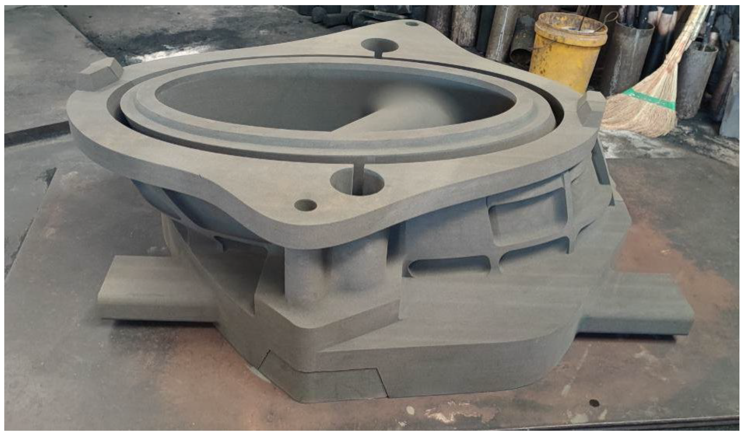
The inlet duct component exhibits a complex structural profile (as illustrated in
Figure 1), with a total length of 2590 mm, an outlet internal diameter of 500 mm, and a wall thickness of 15 mm, qualifying it as a typical large-scale, irregular thin-walled structure. Traditional machining methods not only lead to substantial material wastage but also present numerous challenging processing dead zones. Consequently, the 3D-printed sand shell additive manufacturing process has emerged as the preferred method for this model, owing to its established efficacy in producing shell and tubular structures.
To ensure that the rigidity and strength of the model’s cast components meet experimental requirements, the positioning blocks on either side of the cast inlet duct were removed and subjected to tensile testing (as illustrated in
Figure 2). The results indicated that the strength of the cast components was reduced by approximately 50% compared to forged metal counterparts. Despite this, the cast parts still satisfy the experimental criteria, demonstrating their suitability for wind tunnel testing.
Additionally, non-destructive testing, including ultrasonic and X-ray inspections, was conducted to assess internal defects within the castings. The results, as shown in the accompanying figures, reveal the presence of porosity, which is the primary factor contributing to the reduced casting strength. This defect must be addressed in future applications to enhance the overall performance and reliability of the castings. Future research should focus on optimizing casting parameters and material formulations to minimize porosity and thereby improve the mechanical properties of the cast components.
To address the identified technical challenges, the following solutions have been devised:
1. Segmented Laser Forming: In response to the structural characteristics of the component, in this method, the part is divided into two segments, each subjected to laser forming. A 60° angled support is incorporated on the underside of the internal circular ribs to mitigate stress-induced deformation.
2. Optimized Residual Material Allocation: To account for areas prone to deformation, in this method, residual material is strategically allocated, ensuring that the formed blank meets the requirements for subsequent machining. The design of the 3D-printed blank includes deliberate residual material distribution, promoting more uniform excess material during later processing stages.
These measures aim to enhance the forming process by reducing stress and deformation, thereby ensuring the dimensional accuracy and mechanical performance of the components.
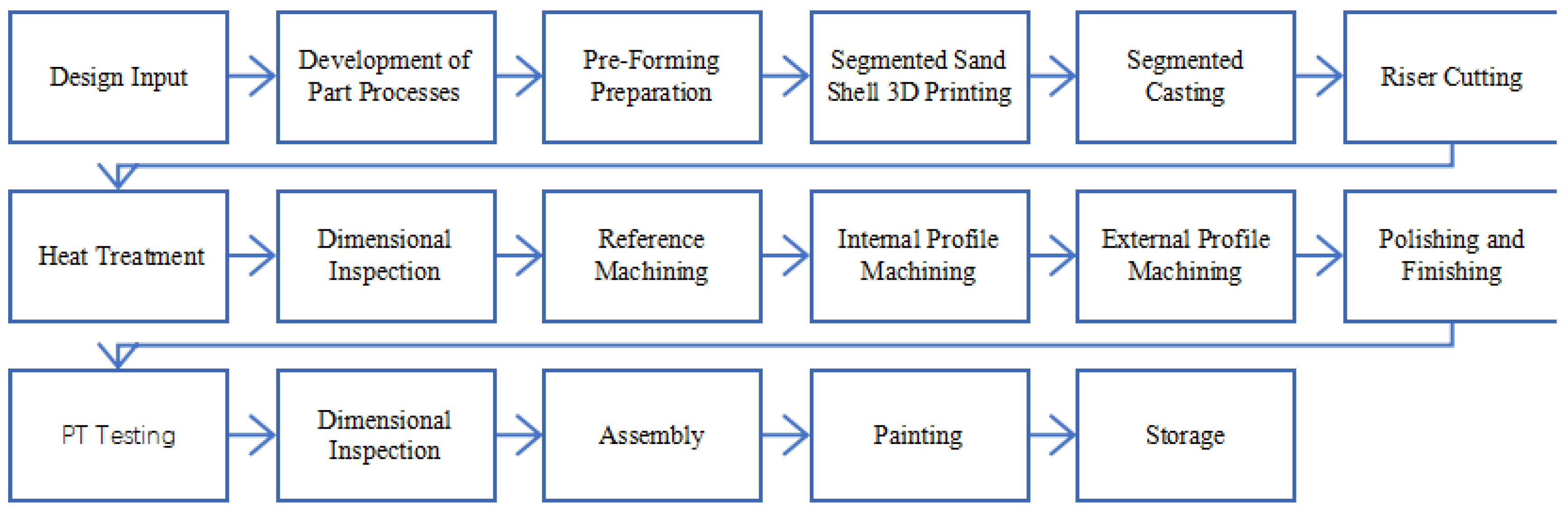
The component is was fabricated using a 3D-printed sand shell for casting, with subsequent shaping performed using a five-axis gantry milling machine. The specific process workflow is was as follows (as illustrated in
Figure 3 and
Table 1):
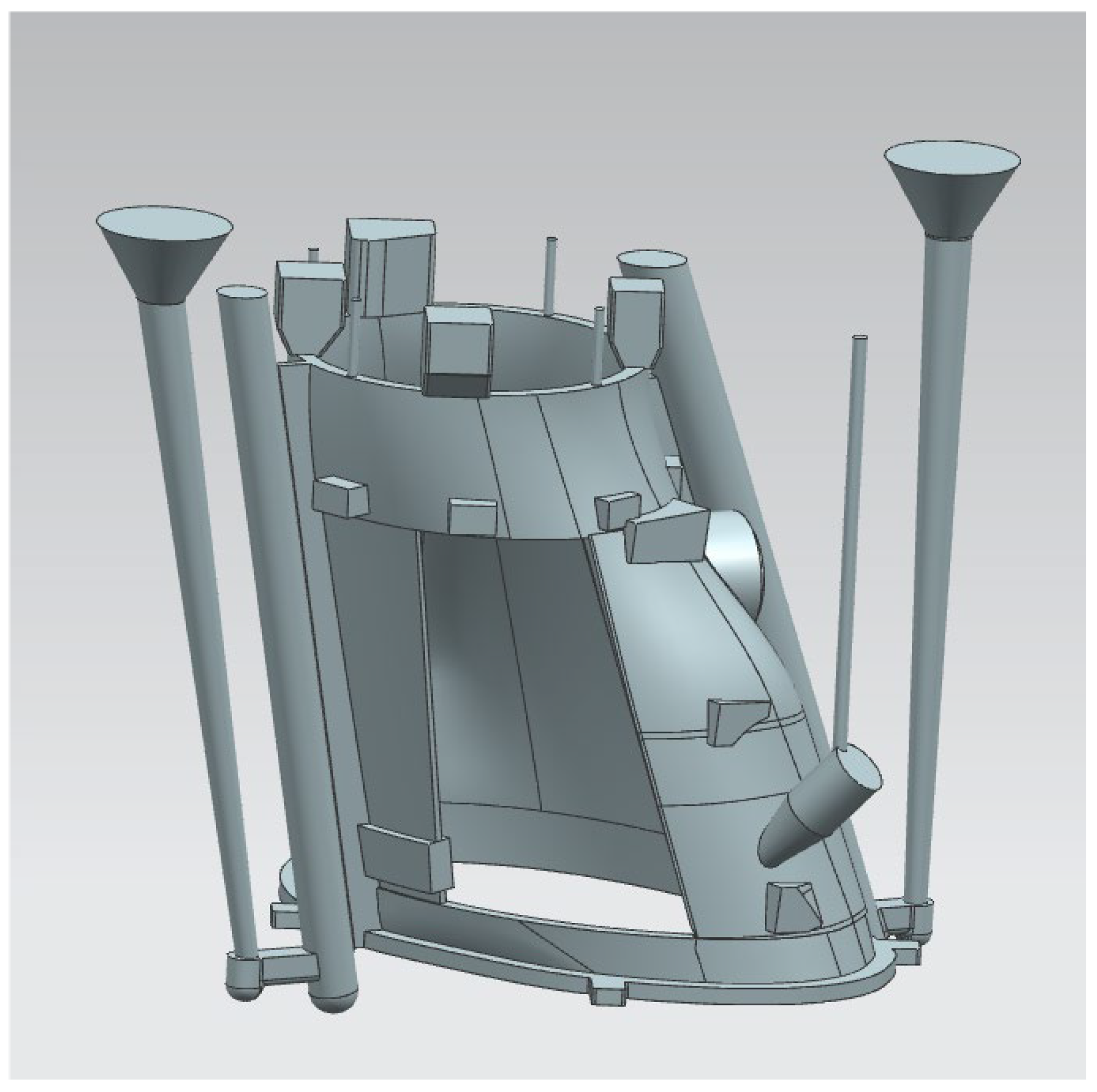
Given the extended length of the model, which is segmented into four distinct sections along the airflow direction, each section utilizes a slot-type gating system for casting. This system facilitates the smooth introduction of molten alloy into the mold cavity, promoting sequential solidification and effective collection of dross at the riser. The process is illustrated in the accompanying schematic diagram (as illustrated in
Figure 4).
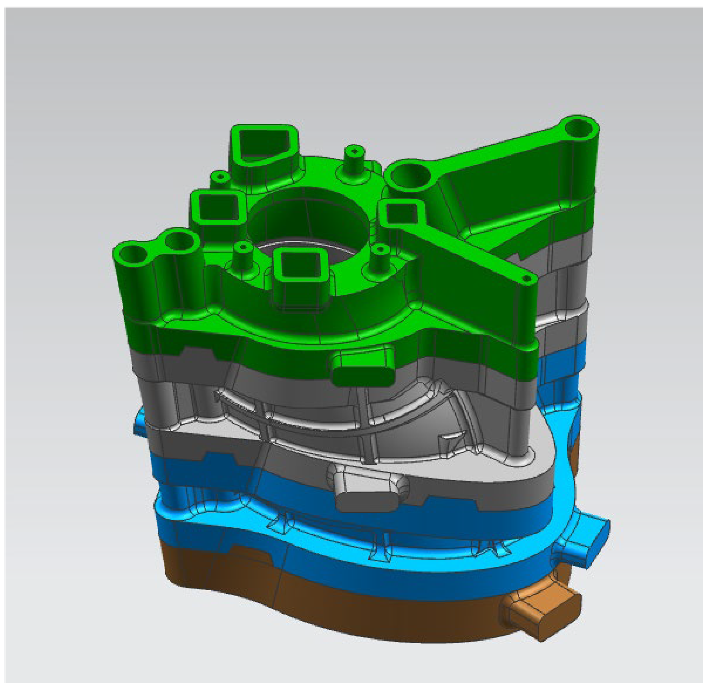
For each segment of the model, taking into account its structural geometry and casting characteristics, multiple sand shell designs were devised and assembled accordingly (as illustrated in
Figure 5).


