Abstract
Along with the trend of aircraft electrification, the penetration of power electronics converters in aircraft energy systems is gradually deepening. Due to the nonlinear behavior and low inertia of aircraft power grids, voltage overshooting and oscillation may occur. Therefore, a voltage surge monitor (VSM) is a safety-critical part in more-electric and electric propulsion aircrafts. VSMs often need a time delay response, so a stable delay time is important. Microprocessors and timer chips can realize accurate time delays but are relatively expensive. Having an extremely low cost and simple structure, RC filters with a discharge diode are popular in consumer electronics operating under narrow temperature ranges (0 °C~70 °C). However, it is unsuitable for aircrafts because of its severe temperature drift cause by the discharge diode. In this paper, a low-cost VSM with temperature compensation is proposed. A detailed mathematical model, simulation, and hardware experiments are conducted for demonstration and verification. Results have shown that the delay time of our VSM circuit has low temperature drift (<0.15%) and accuracy comparable to the typical timer chip LTC6994.
1. Introduction
1.1. The Necessity of a Voltage Surge Monitor in Electrified Aircrafts
According to the statistics of the Intergovernmental Panel on Climate Change (IPCC), civic aviation transportation has become one of the fastest growing areas of greenhouse gas emission [1]. Aircraft electrification is a key technology for green aviation. Airplanes are currently experiencing two stages of electrification: more-electric aircraft (MEA) and electric propulsion aircraft (EPA). In MEAs, hydraulic and barometric energy are replaced with electricity, integrating electric generation, distribution, and consumption devices into one system [2]. Replacing fuel with electricity in primary power, EPA are a major and thorough innovation and revolution in aircraft electrification [3,4,5,6].
Along with the electrification of aviation, power electronics is gradually penetrating into the airplane energy system. The transient and nonlinear behavior of loads usually lead to grid voltage fluctuation. In addition, output voltage overshooting or oscillation also occur due to the low inertia of power electronics system [7]. In the fly-by-wire system of the A380 (see Figure 1), a typical MEA for example, the whole flight control system (FCS) is powered by power conditioning modules (PCMs). The output power quality of PCMs has a direct influence on FCSs.
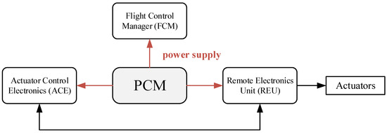
Figure 1.
Power distribution of fly-by-wire system in MEA.
Therefore, the voltage surge monitor (VSM) is indispensable. When the bus voltage or output voltage of a power converter is too high or too low, the VSM will raise a voltage fault flag for failure reporting, protection triggering, or power supply redundancy shifting. In fact, it is already a widely used unit in current aircrafts.
1.2. Time Delay in VSMs
The VSM is not just a voltage comparator because the endurance of loads against voltage over-ranges varies for different voltage values. For instance, the normal 28VDC voltage surge limitation is 47 V/5 ms, 40 V/30 ms, and 17 V/30 ms (RTCA/DO-160G, class-A equipment) [8], as shown in Figure 2. If the output voltage of a PCM is 43 V (greater than 40 V but less than 47 V) or 16 V (less than 17 V), the VSM should raise a fault state within 30 ms. However, if the voltage exceeds 47 V, the delay time becomes 5 ms, which means the VSM must respond earlier.
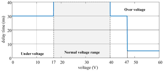
Figure 2.
28VDC normal voltage surge of RTCA/DO-160G class-A equipment.
As can be seen from the above, accurate delay time control is critical in VSMs. If the delay time is too short, an unexpected fault flag will be raised frequently, interfering with the normal function of the aircraft power system. Otherwise, the VSM will fail to alert on the fault state in time when the voltage exceeds the normal range.
Three popular delay methods are listed in Table 1. Microprocessors and timer chips (like the LTC6994 [9,10]) can realize an accurate time delay but are relatively expensive. Having an extremely low cost and simple structure, RC filters with a discharge diode are popular in consumer electronics with a low reliability requirement and narrow operating temperature. However, it is unsuitable for aircrafts because of its severe temperature drift cause by the reverse current of discharge diodes [11]. Resistance and capacitance will also change with temperature, causing a deviation in the RC time constant [12].

Table 1.
Comparison of different delay methods.
1.3. Contribution of This Work
In this paper, a low-cost VSM with low temperature drift is proposed. It derives from the low-cost RC delay circuits in consumer electronics, but contains a temperature compensation scheme. Our temperature compensation is extremely lucid—just by adding a shunt diode to counterbalance the reverse current of discharge diode. Although simple at a glance, detailed mathematical modeling, simulation, and hardware experiments are conducted for demonstration and verification. All results have shown that our simple VSM circuit has low delay time temperature drift and comparable accuracy to timing chips.
2. Architecture of the VSM
2.1. VSM for Electrified Aircrafts
Figure 3 is a simplified illustration of Figure 1, where the PCM distributes power from the aircraft bus bar to the load devices. The VSM monitors the PCM output voltage and raises a voltage surge flag. This flag can be transmitted to loads or to the PCM to activate the protection subsystem.
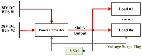
Figure 3.
The VSM in an MEA power distribution system (simplified).
2.2. VSM Behavior Logic
Figure 4 is the architecture of the VSM. The monitored voltage Uin is firstly compared with multiple thresholds, and the comparison results are buffered and then converted into several digital values dk. In each VSM branch, the delay circuit and the AND-gate delay the rising-edge of dk, and Sk becomes logic-high if the time that dk remains high exceeeds tdk.
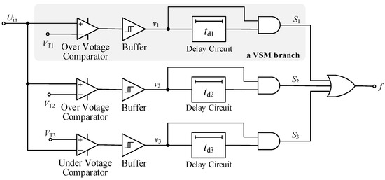
Figure 4.
The proposed delay circuit.
The timing diagram of one VSM branch is shown in Figure 5. If one branch outputs a logic-high, the final output of VSM (f) becomes logic-high, indicating the surging voltage of Uin exceeds the safe limitation.
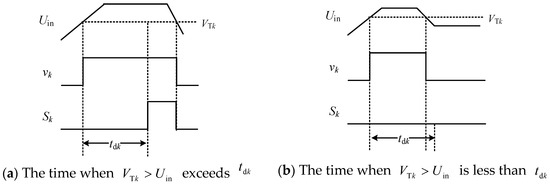
Figure 5.
The timing diagram of a VSM branch (k = 1, 2, …).
3. Low-Cost Delay Circuit with Temperature Compensation
The delay circuit is the most important part of a VSM, which is shown in Figure 6. When the input voltage vi is high , the capacitor C is charged through resistor R. Then, the capacitor voltage u increases and the output vo will become high when . When , the capacitor C is discharged by D1 rapidly, thus resetting the output vo. Shunt diode D2 is added for temperature compensation, and detailed analysis and explanation will be given later. Merely composed of a few passive components and a comparator, the circuit in Figure 6 is a very simple and cheap design.
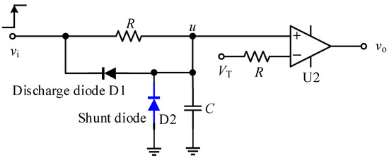
Figure 6.
The proposed delay circuit.
3.1. Component Temperature Characteristics
Since the VSM shall work in a full temperature range (−40 °C~125 °C), resistance R and capacitance C are all functions of temperature T.
where Rnom is the nominal resistance, Tnom = 25 °C is the reference temperature, and α, β1, and β2 are their temperature coefficients.
In order to realize a high precision delay with a low temperature drift, R is usually a high precision resistor with resistance error εR = 0.1% and temperature coefficient α = 25 ppm/°C. In this paper, the C0G MLCC manufactured by muRata is chosen for the delay capacitor C. The temperature coefficients can be obtained from a regression analysis of muRata official data [12]. We have , and .
In a common RC delay circuit analysis, the reverse current of diode D1 is usually neglected. However, this reverse current increases with temperature dramatically. For the aircraft VSMs, the temperature characteristic of the diode reverse current should be taken into consideration for higher delay accuracy and stability. Figure 7 is the reverse current curve. It can be observed that the reverse current is influenced by both temperature T and reverse voltage Vr. For Vr < 20 V, the reverse current can be fitted by Equation (3) based on the data given in Figure 7 [13].
where , and .
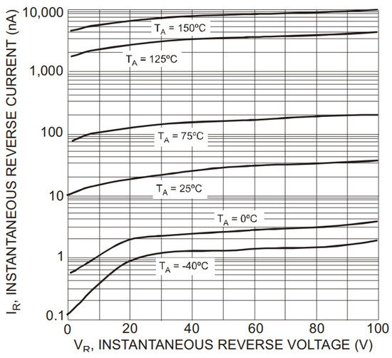
Figure 7.
Diode reverse current (Figure 3 of [13]).
3.2. Circuit Modeling in Full Temperature Range
Based on the component temperature characteristics above, the proposed RC delay circuit can be modeled by a partial differential equation (PDE).
In Equation (4), the capacitor voltage is u, and Irk denotes the reverse current of diode Dk. The input voltage, time, and temperature are vi, t, and T, respectively. If the shunt diode D2 is introduced then m = 1, and m equals 0 otherwise. Diode D1 and D2 have the same parameters.
For the delay time calculation, the stimuli and initial criteria of Equation (4) are
where ε(t) is the unit step function. Then, the delay time td satisfies .
4. Verification
4.1. Temperature Sweep Simulation
To verify the proposed model in Section 3, a VSM is designed subject to Figure 2 and simulated using PSpice. In the simulation circuit of Figure 8, all chips and diodes are PSpice models obtained from official websites of their manufacturer. The temperature sweep simulation results are shown in Figure 9. The solid lines denote the delay time curve calculated by the mathematical model in Section 3, and the dots are PSpice simulation results which is consistent with the mathematical model.
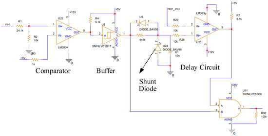
Figure 8.
Simulation circuit in pSpice for temperature sweep.
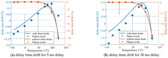
Figure 9.
Temperature drift of VSM delay time.
It is obvious that the delay time rapidly decreases with T in the absence of shunt diode D2, resulting in significantly higher temperature drift or delay time error. By simply adding a shunt diode D2, the delay time deviation is suppressed within ±0.15%, which is comparable to the temperature drift data given in the LTC6994 datasheet.
4.2. Hardware Experiment
For further verification, a VSM prototype is built as in Figure 10. Important devices in the prototype are listed in Table 2.
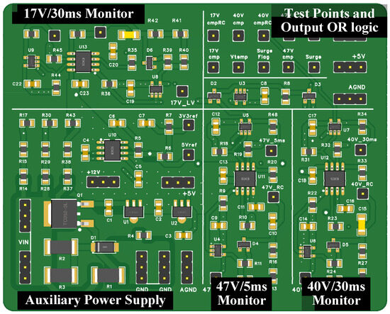
Figure 10.
The VSM prototype to monitor the 28VDC normal voltage surge of Figure 2.

Table 2.
Important devices in the prototype.
Empirical waveforms of three VSM branches are shown in Figure 11, Figure 12 and Figure 13. In Figure 11, for example, when the input voltage (the green curve) exceeds 47 V, the voltage comparator output becomes 5 V (the orange curve). Then, the capacitor begins to be charged, and its voltage increases gradually (the red curve). When the capacitor voltage reaches , the final output of the 47 V/5 ms monitor toggles (the blue curve). The rising edge delay between the orange curve and the blue curve is exactly 5 ms. Similarly, the delay time in Figure 12 and Figure 13 is 30 ms, indicating the effectiveness of the proposed VSM.
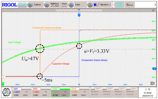
Figure 11.
Output of 47 V/5 ms over-voltage monitor.
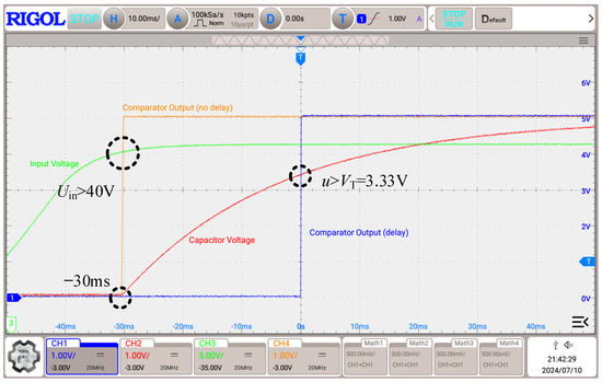
Figure 12.
Output of 40 V/30 ms over-voltage monitor.
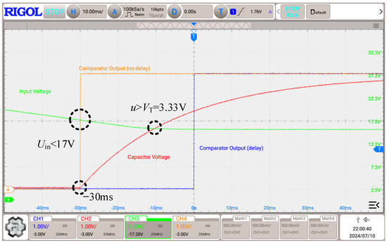
Figure 13.
Output of 17 V/30 ms under-voltage monitor.
4.3. Delay Circuit Comparison
After the simulation and experiment, a comparison of performance and cost are conducted between the delay method in this paper and the timer chip LTC6994 (see Table 3). Here, the microprocessor is no longer considered because of its complexity (software involved) and high cost. Since the resistance and capacitance error are 0.1% and 1% in Table 2, the RC time constant error of the VSM is . So, the delay time accuracy of this paper is comparable to LTC6994, but the cost is only 21.3% that of LTC6994. Therefore, the delay method proposed in this paper has advantages in cost without too much performance degradation.

Table 3.
Comparison between this paper and LTC6994.
In conclusion, both timer chips and the circuit in this paper are feasible methods for VSMs in electrified aircraft. For a low-cost design, the circuit in Figure 6 is more suitable. But when the available PCB area is extremely limited, the timer chip is a better choice due to its high integration.
5. Conclusions
In this paper, a low-cost VSM with temperature compensation is proposed. The architecture and behavior logic of the VSM is briefly demonstrated. Then, the mathematical model of the VSM is built for circuit operation under a full temperature range. To verify the proposed VSM, both a PSpice simulation and hardware experiment are carried out. The PSpice temperature sweep results and our model are generally consistent, and the delay time drift decreases from 10% to 0.15% by simply adding a shunt diode. Physical experiment results show that the proposed VSM can respond according to the expected delay time and voltage threshold. Finally, a comparison between the proposed VSM and the typical timer chip LTC6994 is given in this paper. The VSM delay time accuracy is comparable to LTC6994, but the cost is only 21.3% that of LTC6994.
Author Contributions
Conceptualization, Z.S.; methodology, Z.S.; validation, Z.S. and Q.S.; formal analysis, Z.S. investigation, Y.M.; resources, Y.M. and J.H.; data curation, Z.S.; writing—original draft preparation, Z.S.; writing—review and editing, Z.S. and Q.S.; visualization, Z.S.; supervision, Y.M. and J.H.; project administration, Y.M. All authors have read and agreed to the published version of the manuscript.
Funding
This research received no external funding.
Institutional Review Board Statement
Not applicable.
Informed Consent Statement
Not applicable.
Data Availability Statement
The original contributions presented in this study are included in the article. Further inquiries can be directed to the corresponding author.
Conflicts of Interest
The authors declare no conflict of interest.
References
- Wang, Y. Status quo and prospect of civil aviation decarbonization research from the ATM perspective. Civ. Aviat. Manag. 2024, 1, 25–28. [Google Scholar]
- Jones, R.I. The more electric aircraft—assessing the benefits. Proc. Inst. Mech. Eng. Part G J. Aerosp. Eng. 2002, 216, 259–269. [Google Scholar] [CrossRef]
- Kong, X.; Zhang, Z.; Lu, J.; Li, J.; Yu, L. Review of electric power system of distributed electric propulsion aircraft. Acta Aeronaut. Astronaut. Sin. 2018, 39, 46–62. [Google Scholar]
- Ansell, P.J.; Haran, K.S. Electrified Airplanes: A Path to Zero-Emission Air Travel. IEEE Electrif. Mag. 2020, 8, 18–26. [Google Scholar] [CrossRef]
- Jones, J.J. Electrical Emissions of Airplanes Flying in Electrified Clouds and Their Effect on Airplane Measurements of Cloud Electric Fields; NASA: Washington, DC, USA, 1991; Volume 1. [Google Scholar]
- Seitz, A.; Isikveren, A.T.; Hornung, M. Pre-Concept Performance Investigation of Electrically Powered Aero-Propulsion Systems. In Proceedings of the 49th AIAA/ASME/SAE/ASEE Joint Propulsion Conference, San Jose, CA, USA, 15–17 July 2013. [Google Scholar]
- Corcau, J.; Dinca, L. Stability Studies of Power Systems for More Electric Aircraft. In Proceedings of the 2022 International Symposium on Power Electronics, Electrical Drives, Automation and Motion (SPEEDAM), Sorrento, Italy, 22–24 June 2022; pp. 861–864. [Google Scholar]
- RTCA. “DO-160G: Environmental Conditions and Test Procedures for Airborne Equipment.” RTCA, Inc., 2010. Available online: https://www.rtca.org/ (accessed on 12 July 2024).
- Analog Devices. “LTC6994-1/LTC6994-2” Analog Devices, Inc. Available online: https://www.analog.com/media/en/technical-documentation/data-sheets/LTC6994-1-6994-2.pdf (accessed on 12 July 2024).
- Srivastava, S.; Kumar, Y.; Thakur, S.K. Simulation studies on 5 kV/5 A power supply using pulse step modulation technique. In Proceedings of the Indian Particle Accelerator Conference (InPac), New Delhi, India, 18–21 November 2019. [Google Scholar]
- Sze, S. Physics of Semiconductor Devices. Wiley-Interscience: New York, NY, USA, 1970. [Google Scholar]
- Murata Manufacturing Co., Ltd. “MLCC Simulation Surfing.” Murata Electronics. Available online: https://ds2.murata.co.jp/simsurfing/mlcc.html?lcid=zh-cn&jis=false&md5=d4a869fdd431efb8f824ec48c8f39463# (accessed on 12 July 2024).
- DIODE Inc. BAV99 Dual Surface-Mount Switching Diode. DIODE Inc. Available online: https://www.diodes.com/assets/Datasheets/BAV99.pdf (accessed on 12 July 2024).
Disclaimer/Publisher’s Note: The statements, opinions and data contained in all publications are solely those of the individual author(s) and contributor(s) and not of MDPI and/or the editor(s). MDPI and/or the editor(s) disclaim responsibility for any injury to people or property resulting from any ideas, methods, instructions or products referred to in the content. |
© 2025 by the authors. Licensee MDPI, Basel, Switzerland. This article is an open access article distributed under the terms and conditions of the Creative Commons Attribution (CC BY) license (https://creativecommons.org/licenses/by/4.0/).