Abstract
In the damage tolerance analysis of aircraft panels, it was necessary to frequently apply complex boundaries and loads to simulate crack propagation. It was difficult to simulate crack propagation with the conventional finite element method. In this paper, a convenient method for crack propagation simulation in thin-walled structures was proposed. This method combined the extended finite element method (XFEM) and level-set method (LSM). Crack insertion, analysis, result extraction and automatic propagation were realized through the secondary development script in the ABAQUS platform. A specimen with a single center crack was simulated to study the crack propagation behavior under tensile and bending conditions. Also, multiple-crack propagation was simulated. The present work shows that the developed method can not only take the complex loading and boundary conditions into account, but also can give good predictions on the crack analysis. This method provided a convenient and effective secondary development of ABAQUS to solve complex crack problems.
1. Introduction
Different types of panel structures are widely used in aircraft frames. The crack propagation behavior relevant to the damage tolerance capability is one of the most important factors for aircraft safety. The finite element method (FEM), as a powerful tool, has been widely used to analyze the crack initiation and propagation process of the cracked aircraft panels. However, it is essential to define the shape function as a continuous function in the traditional FEM since the shape function and material property must be simultaneously continuous within the finite element. Therefore, the crack surface must be set as one side of the element, and the crack tip must be set as the element node if there is a strong discontinuity problem (displacement discontinuity). There is strong singularity around the crack tip; consequently, it is necessary to increase the mesh density here for the purpose of improving the computational accuracy. Due to these limitations, it is not straightforward for the traditional FEM to solve crack propagation problems of the cracked structures.
The extended finite element method (XFEM), as a prospective method, has gained extensive attention for its use in stress analysis around a crack. Unlike the crack modeling of the traditional FEM, the XFEM allows for the mesh independent modeling of discontinuities and eliminates the requirement for a discontinuity to conform to element boundaries. The XFEM allows arbitrary discontinuity within an element so that the domain around the crack tip can be discretized without explicitly meshing the discontinuity. This method was first proposed by Belytschko [1] in 1999. During the last decade, this method has been widely applied to study crack characteristics. Some commercial codes, such as ABAQUS, introduced the XFEM function. Bordas et al. [2] implemented the XFEM as an object-oriented library in C++. Paris et al. [3] developed the MATLAB code named MXFEM to accurately simulate inclusions, void and cracks. The drawback of this method was not being able to build a complicated geometrical model, loading and boundary conditions. Liu et al. [4,5] employed the XFEM function in ABAQUS to study the propagation of multiple cracks in finite plates with a hole. The results confirmed the effectiveness of this method, but did not provide enough data outputs of the cracks.
The secondary development was employed to code the multi-crack propagation program package based on the ABAQUS platform. This package was then used to calculate the exact stress intensity factor of the crack tip and realize the simulation of crack propagation.
2. Background of the Extended Finite Element Method
2.1. Discontinuous Displacement Field
The extended finite element concept was proposed firstly by Professor Belytschko’s research group [1]. Until 2000, the extended finite element method was used frequently [6]. The XFEM was a FEM technology that was used to simulate discontinuity problems. The advantages of the traditional FEM were maintained, and the discontinuity problems were modeled by using the special function of continuous displacement field. The displacement can be expressed as follows:
where is the set of all nodes; is the set of the element nodes cut by the moving crack (indicated by ○ in Figure 1); is the set of the nodes of elements including crack tip (indicated by □ in Figure 1); , and are the shape function of the corresponding node; and are the displacements of the corresponding nodes, respectively.
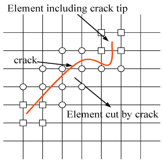
Figure 1.
Definition of the enrichment support domain.
is the Heaviside step function. This function is used to represent the crack at a distance from the tip. The Heaviside step function is given as follows:
is the crack tip asymptotic displacement function. For a linear elastic crack tip, four enrichment functions [7] are used to incorporate the crack tip displacement field into elements containing the crack tip, as shown below:
where r and θ are the polar coordinates in the local crack tip coordinate system.
2.2. Level-Set Method
The level-set method (LSM) is a numerical method to track moving interfaces. This method presents the crack interface by defining a zero level-set function. The crack location is presented by the combination of the crack surface level set and the crack tip level set ψ. The interfaces that define these two level-set methods are perpendicular, as shown in Figure 2.
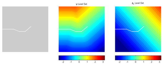
Figure 2.
The description on the crack of LSM.
φmin and φmax present the minimum and maximum value of the crack surface level set at the node of an element, respectively; ψmin and ψmax present the minimum and maximum value of the crack tip level set, respectively. If ψmax < 0 and φminφmax < 0, then this element is cut by a crack. If ψminψmax < 0 and φminφmax < 0, a crack tip is included within the element. The crack information in an element is obtained based on the values of ψ and φ for the purpose of determining whether the node is enriched or not.
The level-set method can be used to track and locate the crack trail in the XFEM expediently. The elements cut by a moving crack and the elements including the crack tip are ascertained, and then the element integral will be carried out in the following step.
2.3. Element Integration
Due to the existence of cracks in parts of the elements, the results calculated by direct Gaussian integration show poor accuracy. These elements are divided into some sub-elements where the displacement is continuous. Element integration is turned into sub-element integration, so the computational results have higher precision.
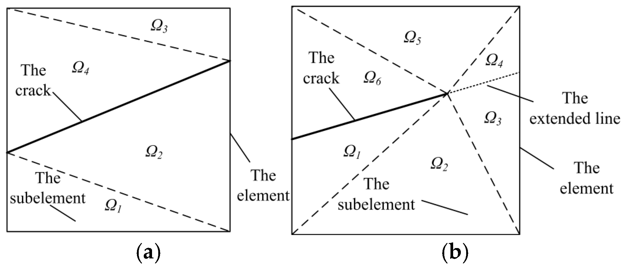
For the element cut by a crack, as shown in Figure 3a, the element is divided into some triangles. The Gaussian integration algorithm is executed on each triangle. For the element including the crack tip, the element is divided into some triangles by extending the crack, as shown in Figure 3b. As was the case for the elements cut by a crack, the Gaussian integration is also executed on each sub-element.

Figure 3.
The division of crack-related elements. (a) The element cut by a crack; (b) the element including the crack tip.
The element integration algorithm in this paper was included in ABAQUS® 6.14 software. It is not necessary to perform additional processing. The elaboration herein was used to illustrate the difference between the XFEM and the traditional FEM in the analytical process of the element integration.
3. Introduction to the Secondary Development and the Program Procedures
3.1. The Secondary Development
The secondary development based on the ABAQUS platform was used to simulate the crack propagation process due to its powerful modeling and program capability. The Abaqus® 6.9 release [8] introduced the basic XFEM functionality to the Abaqus® CAE environment and was updated in later versions. The Abaqus® implementation of the XFEM is somewhat different from that which was previously presented in this paper. For the algorithm within ABAQUS, the nodes of enriched element were only enriched with the Heaviside function. In another words, all enriched elements were elements cut by the moving crack rather than elements including the crack tip. This leads to poor accuracy of the resulting J-integral calculation [9]. In addition, the XFEM functionality in ABAQUS only allowed the static analysis procedure of the crack in the numerical analysis of fracture mechanics. This means that different crack lengths and types need different models. If the crack propagation process was simulated, repeated modeling would have been requested for every step of crack propagation. The multi-crack propagation needs more modeling efforts. With these limitations in mind, in this study, we aimed to solve the problems of crack propagation and to extract the analysis results through the secondary development package.
3.2. The Program Package Description
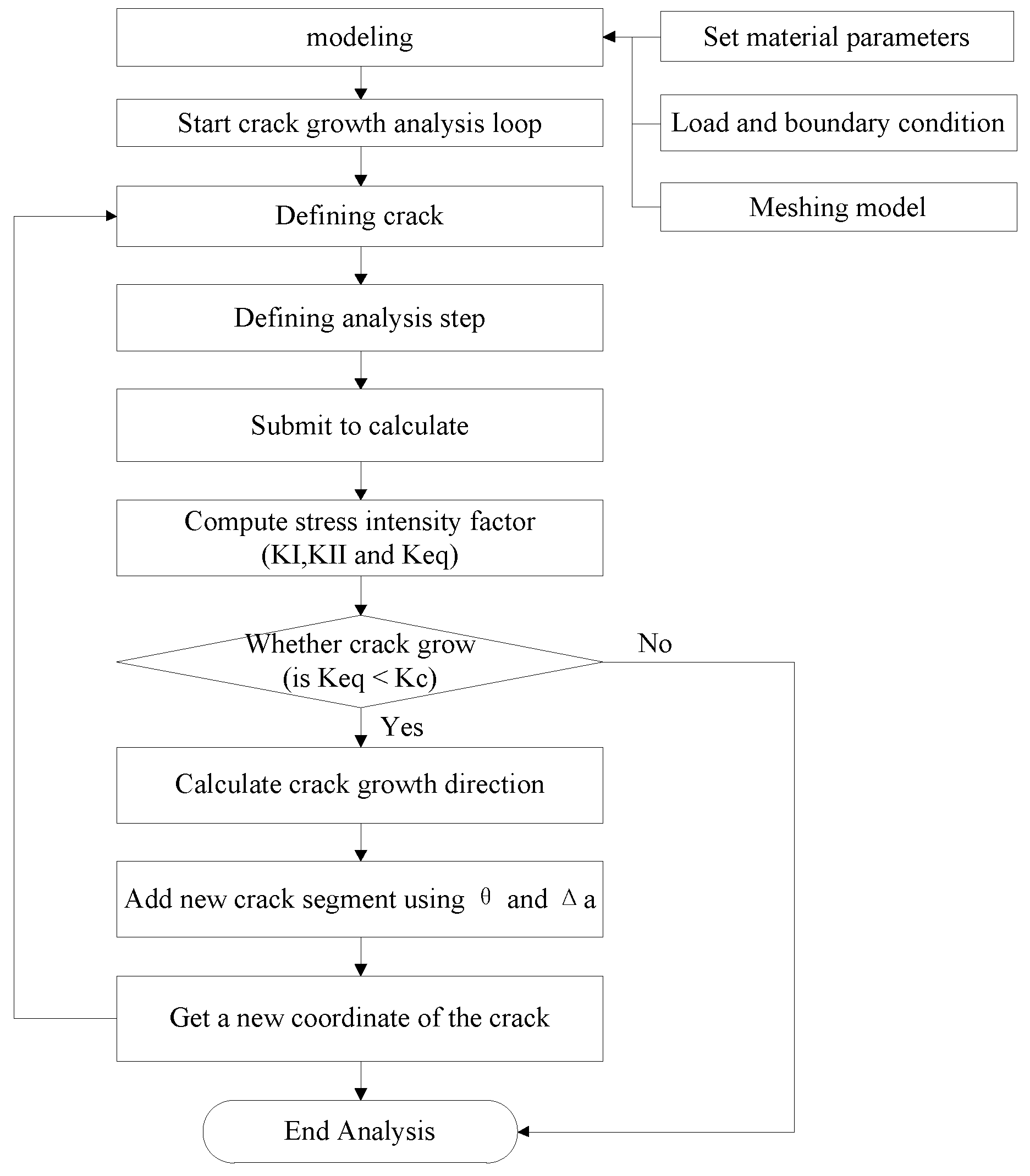
Figure 4 indicates the flow chart of the crack propagation process. Modeling, the material, the load, the boundary and meshing are created in ABAQUS. The script program is used to read the model, define the crack location, create the analysis step, submit the task to calculate and determine if the crack grows or not based on the values of the stress intensity factors. The script program will be terminated if the crack does not grow. If the crack grows, the iteration algorithm is executed repeatedly for the purpose of obtaining the new coordinate of the crack and returning the previous step of the crack definition until the restricted conditions are reached. The modeling work is independent of the script program; thus, there is no interaction between the complexity of the model and the script program. Both the simple model and the complicated model can be imported for the crack analysis.
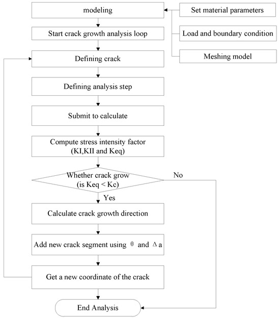
Figure 4.
The flow chart of the crack propagation process.
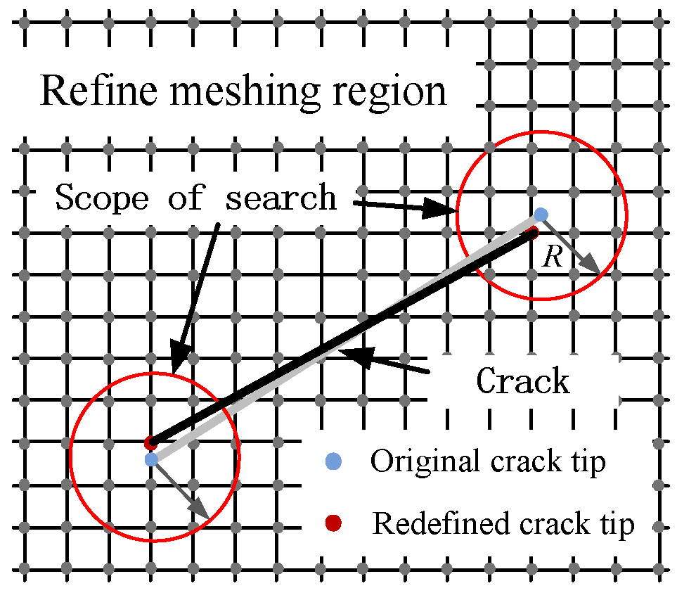
In ABAQUS, the crack tip can only be located at a node or on the boundary of an element, since the enriched element nodes are only enriched with the Heaviside function. To solve this problem properly, the crack tip is located at a node in this study. The determination of the crack tip location is shown in Figure 5. The actual crack is represented as a dotted line in Figure 5. The crack needs to be redefined if the crack tip is inside the element. The nodes within the scope of an R-value radius around the actual crack tip are marked as red. The distance between each red node and the actual crack tip is calculated. The red node that has a minimum distance is selected as the new crack tip. The location of the blue node is then determined as the location of the new crack tip. As a result, the new crack is represented as a black solid line in Figure 5.

Figure 5.
The determination of the crack tip location during the crack propagation.
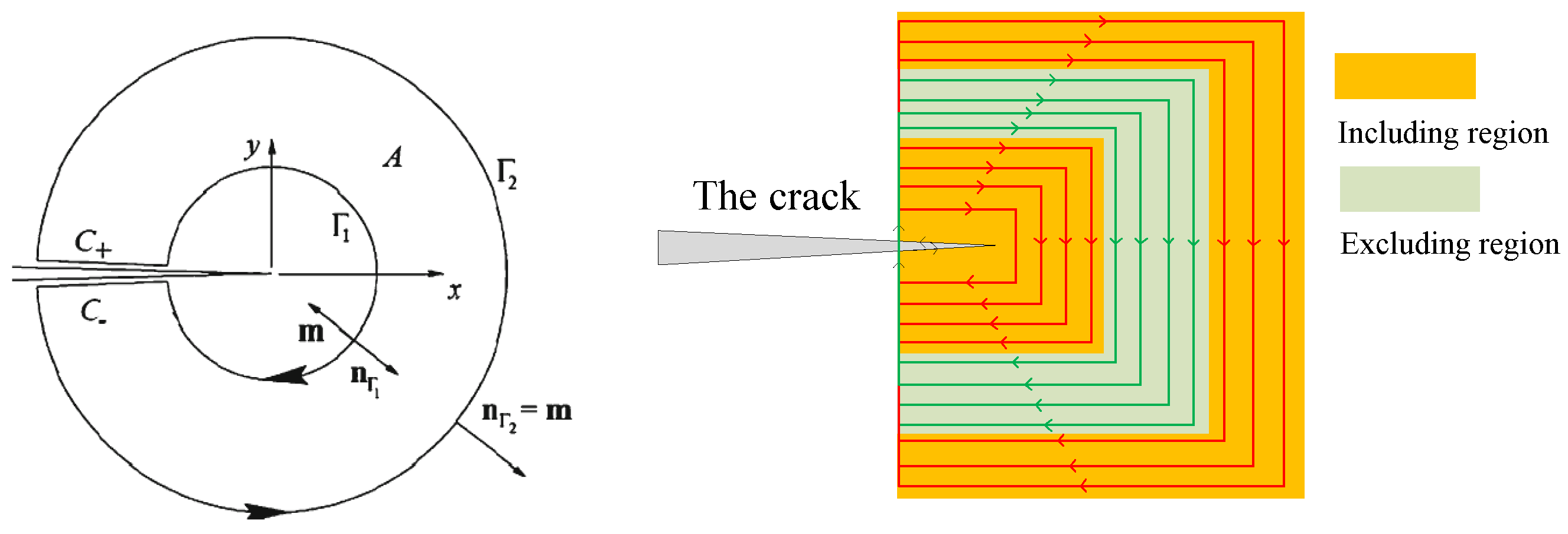
The XFEM functionality in ABAQUS is used to define the crack. However, the calculated value of the stress intensity factor around the crack tip has poor accuracy since it cannot simulate the stress field here. There are two methods to solve this drawback. The first method is the use of mesh refinement. It is shown that accurate results are achieved if the mesh size is below 3% of the crack size [10]. The other method is to use the contour integral, and then select the results on purpose. Twenty different integrations were conducted in this paper. Affected by the imprecise stress field around the crack tip, the outermost five contour integrations were chosen to ensure the accuracy of the results, as shown in Figure 6.

Figure 6.
The preferential contour integration around the crack tip.
3.3. Crack Propagation Parameter Analysis
The important parameters are and in the secondary development program. presents the crack growth increment and presents the crack growth direction, respectively, in the current crack growth step. The maximum circumferential stress criterion is used to evolve the crack, which will propagate in the direction where is at its maximum. The angle of crack growth is given by the following equation:
where and c are the mixed-mode stress intensity factor. The magnitude of the incremental crack growth can be determined either using a constant crack growth increment, typically assumed using crack growth law. Paris’ law, which is widely used in engineering, is described as the correlation between da and dN. Tanaka [11] reported the following version of that is suitable for mixed-mode stress intensity factors:
Thus, the direction of crack growth is a function of mixed-mode stress intensity factors. The domain forms of the interaction integrals [12,13] are used to calculate the mixed-mode stress intensity factors. For a general mixed-mode situation, the relationship between the J-integral and the stress intensity factors is as follows:
is defined by a state of plane stress or plane strain, where assumes the value of and for plane stress and plane strain states, respectively. In order to calculate the mixed-mode stress intensity factors, an auxiliary stress state is superimposed onto the stress and displacement fields from the XFEM analysis. The XFEM solutions are denoted with superscript (1) as , and , while those from the auxiliary state are denoted as , and .
The J-integral form and the crack tip opening direction are assumed to correspond to the global x-direction. The two stress states can be superimposed to form the following equation:
Separating the J-integrals for pure state 1 and auxiliary state 2, Equation (7) produces an interaction term. Since two cracked configurations are superimposing onto one another, the interaction term can be written as follows:
The stress intensity factors for the current state can be found by separating the two modes of fracture. By selecting = 1 and = 0, we are able to solve , as shown below:
A similar procedure can also be followed such that is given by the following equation:
If stress intensity factors are obtained, crack growth parameters can be easily computed. And if is fixed, the number of corresponding cycles is computed using the following equation:
4. Numerical Verification
4.1. Application in the Mode I Crack Propagation
A finite plate with a single center crack, subjected to unit uniaxial tension, was considered to study the crack growth, as shown in Figure 7. The material used was the LY12-CZ alloy. The material properties were given as follows: elastic modulus E = 67,900 MPa and Poisson’s ratio v = 0.3. The stress intensity factor, relevant to the crack length a, was calculated as outlined below [14].
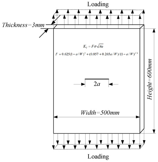
Figure 7.
The specimen with a single center crack.
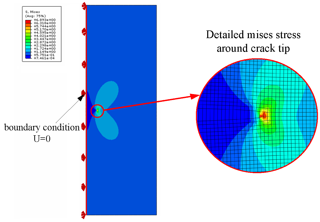
In order to simplify modeling, a half crack model was established with central symmetry. The surface of symmetry imposed a fixed boundary condition in the horizontal direction. The crack length propagated from 30 mm to 58 mm during fifteen increments of crack growth. The Mises stress contour during the crack propagation is shown in Figure 8. This figure illustrates the stress field around the crack tip in detail. It is clearly shown that the stress distribution around the crack tip is shaped as half of a butterfly.
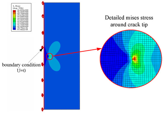
Figure 8.
The Mises stress contour plot during crack propagation process.
The stress intensity factors of different crack lengths were recorded during crack propagation. The comparison between the results from the XFEM and the exact results are shown in Table 1. As can be observed in Table 1, the difference between the numerical results and analytical results was rather small. The maximum error between these two results was less than 1.23%.

Table 1.
The comparison between the XFEM result and the exact result.
4.2. Application on the Multiple-Crack Propagation
The single-crack situations, subjected to tension conditions, were studied as shown above. The script program, developed in this paper, could also be applied to multi-crack cases. The geometry configuration of the specimen with multiple cracks is shown in Figure 9. The sizes of three cracks and the specimen are described in detail in the figure.
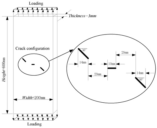
Figure 9.
The geometry configuration of the multi-crack specimen.
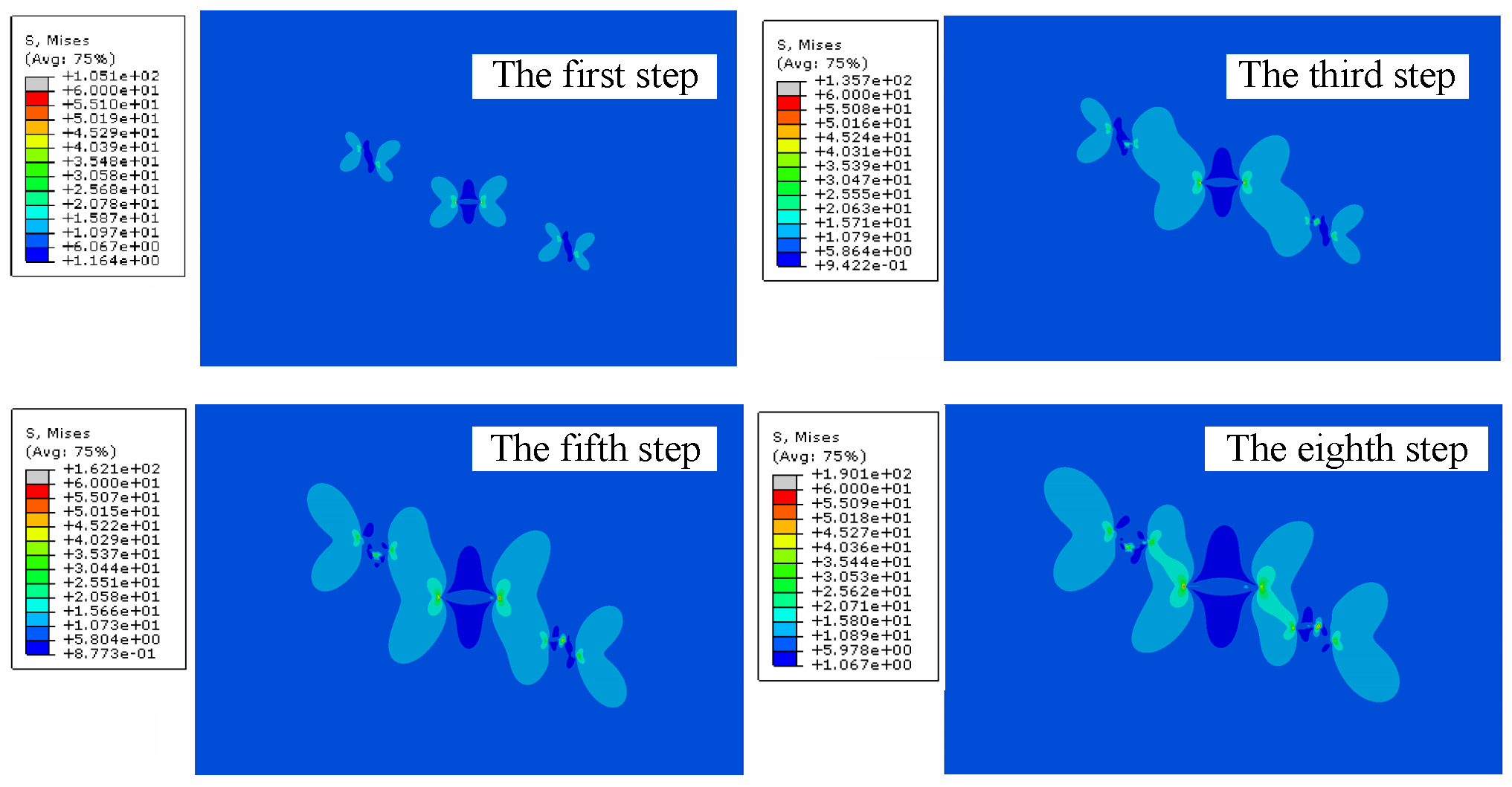
In this case, the mesh size including the crack was 0.125 mm and the crack growth increment was 1.5 mm. The stress intensity factors were extracted by the average of 20 different counter integration steps. The number of crack propagation steps was eight in this paper. The four stress contours for different propagation steps are shown in Figure 10. As seen in this figure, the interaction effect between cracks was not obvious before the cracks started to grow. However, the crack interaction phenomenon appeared to increase rapidly as the crack propagated. This work presented some important information for research on multiple-crack propagation.

Figure 10.
The Mises stress contour plot during the crack propagation process.
5. Conclusions
In this work, the secondary development of ABAQUS, using the Python script, was used to create a program package for crack propagation simulations. For the developed method combined with the XFEM, it is not necessary to re-mesh the cracked finite element model during crack propagation. This method can be used for stress intensity factor calculations and crack path predictions with high efficiency and accuracy. The script program was verified through the multi-cracked specimen, and the single-cracked specimens subjected to different loading conditions. The predicted stress intensity factors around the moving crack tip and the crack growing path were simultaneously confirmed to be in good agreement with the exact results and the existing results. As a consequence, the present work is interesting and valuable for studying crack growth behavior, which plays a key role in the damage tolerance evaluation of aircraft panels.
Author Contributions
Conceptualization, W.Z.; methodology, X.C.; validation, W.Z.; formal analysis, J.Y. All authors have read and agreed to the published version of the manuscript.
Funding
This research received no external funding.
Informed Consent Statement
Informed consent was obtained from all subjects involved in the study.
Data Availability Statement
Data are contained within the article.
Conflicts of Interest
The authors declare no conflicts of interest.
References
- Moes, N. A finite element method for crack growth without remeshing. Int. J. Numer. Methods Eng. 1999, 46, 131–150. [Google Scholar] [CrossRef]
- Bordas, S. An extended finite element library. Int. J. Numer. Methods Eng. 2006, 71, 703–732. [Google Scholar] [CrossRef]
- Pais, M. Variable Amplitude Fatigue Analysis Using Surrogate Models and Exact XFEM Reanalysis; University of Florida: Gainesville, FL, USA, 2011. [Google Scholar]
- Jian, L. Simulation Study of Multiple Crack Extension of Holey Plate Based on Extended Finite Element Method. Fail. Anal. Prev. 2013, 8, 326–330. [Google Scholar]
- Fan, J. simulation on elastic-plastic fatigue crack growth behavior. Chin. J. Mech. Eng. 2015, 51, 33–40. [Google Scholar] [CrossRef]
- Daux, C. Arbitrary branched and intersecting cracks with the extended finite element method. Int. J. Numer. Methods Eng. 2000, 48, 1741–1760. [Google Scholar] [CrossRef]
- Fleming, M.; Belytschko, T. Enriched element-free Galerkin methods for crack tip fields. Int. J. Numer. Methods Eng. 1997, 40, 1483–1504. [Google Scholar] [CrossRef]
- Dassault Systemes. Abaqus 6.9 Overview. 2009. Available online: http://www.simulia.com/download/Webinars/Abaqus69_overview/Abaqus69Overview-new.html (accessed on 25 July 2024).
- Giner, E. An Abaqus implementation of the extended finite element method. Eng. Fract. Mech. 2009, 76, 347–368. [Google Scholar] [CrossRef]
- Vethe, S. Numerical Simulation of Fatigue Crack Growth; Norwegian University of Science and Technology: Trondheim, Norway, 2012. [Google Scholar]
- Tanaka, K. Fatigue Crack Propagation from a Crack Inclined to the Cyclic Tension Axis. Eng. Fract. Mech. 1974, 6, 493–507. [Google Scholar] [CrossRef]
- Shih, C. Elastic-plastic analysis of cracks on bimaterial interfaces: Part I—Small scale yielding. J. Appl. Mech. 1988, 55, 299–316. [Google Scholar] [CrossRef]
- Yau, J. A mixed-mode crack analysis of isotropic solids using conservation laws of elasticity. J. Appl. Mech. 1980, 47, 335–341. [Google Scholar] [CrossRef]
- Murakami, Y. Stress Intensity Factors Handbook; Pergamon: New York, NY, USA, 1987. [Google Scholar]


Disclaimer/Publisher’s Note: The statements, opinions and data contained in all publications are solely those of the individual author(s) and contributor(s) and not of MDPI and/or the editor(s). MDPI and/or the editor(s) disclaim responsibility for any injury to people or property resulting from any ideas, methods, instructions or products referred to in the content. |
© 2025 by the authors. Licensee MDPI, Basel, Switzerland. This article is an open access article distributed under the terms and conditions of the Creative Commons Attribution (CC BY) license (https://creativecommons.org/licenses/by/4.0/).