Proceeding Paper

Quantitative Deterioration Evaluation of Heavy-Duty Anticorrosion Coating by Near-Infrared Spectral Characteristics †

1
Department of Mechanical Engineering, Kobe University, Kobe 657-8501, Japan
2
Honshu-Shikoku Bridge Expressway Co., Ltd., Kobe 651-0088, Japan
*
Author to whom correspondence should be addressed.
Presented at the 16th International Workshop on Advanced Infrared Technology & Applications, 26–28 October 2021; Available online: https://aita2021.sciforum.net/.
Eng. Proc. 2021, 8(1), 26; https://doi.org/10.3390/engproc2021008026
Published: 25 November 2021

Abstract

:
Heavy-duty anticorrosion coatings are applied on the surface of steel bridges for protecting against corrosion. By aging deterioration, the coating is worn from the surface year by year. Appropriate re-painting construction programs should be adopted for the maintenance of the bridges according to the evaluation of wear extent. Experimental studies were conducted with the aim of quantitative estimation of the degree of abrasion of the top coat thickness. It was found that there was a correlation between the top coat thickness and the observed infrared intensity and that this calibration relationship could be used to estimate the top coat thickness.

1. Introduction

Steel bridges should be properly maintained against main causes of deterioration such as “corrosion” and “fatigue” to provide safe service over the long term. For the maintenance of the fatigue in steel bridges, Sakagami et al. [1] proposed maintenance schemes using infrared thermography. Meanwhile, to prevent the corrosion of the steel bridges, heavy-duty anticorrosion coatings shown in Figure 1 are mainly employed. The heavy-duty anticorrosion coating consists of sacrificial protection coat, under coat, intermediate coat, and top coat. The sacrificial protection coat is made of inorganic zinc-rich paint to affect electrochemical corrosion protection. The under coat and intermediate coat are made of epoxy resin paint. The top coat is located on the outermost surface of the heavy-duty anticorrosion coating, so excellent weather resistance paint, such as fluororesin paint, is employed. The thickness of the sacrificial protection coat, the under coat, the intermediate coat, and the top coat are 75 μm, 120 μm, 30 μm, and 25 μm, respectively.
To maintain the integrity of the coating, it is desired to repaint before its deterioration becomes prominent. Therefore, preventive maintenance is required for the maintenance and management of long-span bridges to detect the deterioration of the coating at an early stage. For the heavy-duty anticorrosion coating, it is difficult to repaint the sacrificial protection coat on-site. Further, the deterioration progress rate of the under coat and the intermediate coat protecting the sacrificial protection coat is much higher than that of the top coat. Therefore, it is important to accurately detect the exposure of the intermediate coat due to the loss of the top coat to ascertain the degree of coating deterioration at an earlier stage. In terms of inspection methods for the coating, the visual inspection is widely applied. However, the evaluation by the human eye is not objective and requires a great deal of time for inspection. Sakagami et al. [2] suggested an inspection method to detect the exposure of the intermediate coat by the difference of near-infrared spectral characteristics of the top coat and intermediate coat. To further improve the effectiveness of this inspection method by near-infrared spectral characteristics, it is desirable to predict the exposure of the intermediate coat in advance by quantitatively detecting the amount of deterioration degree of the top coat before the intermediate coat is exposed.
Therefore, the authors focused on the quantitative evaluation of the infrared reflection energy of the heavy-duty anticorrosion coating. This study develops a method to quantitatively evaluate the thickness of the top coat using the difference of the infrared reflection energy with various thicknesses of the coating.

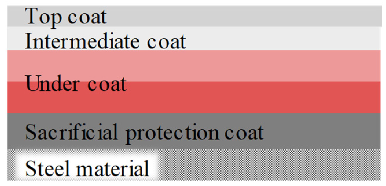
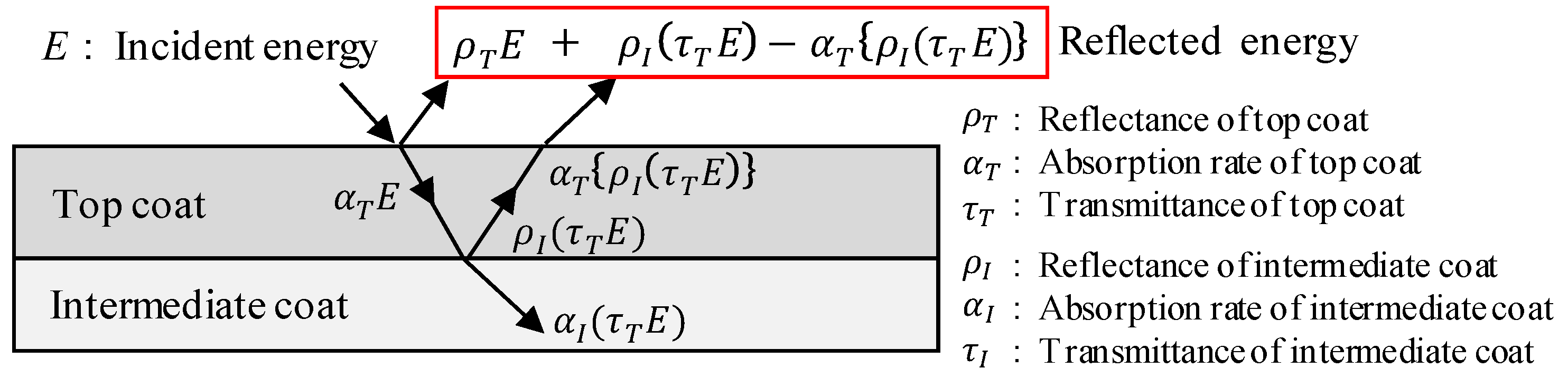
2. Principle of Quantitative Nondestructive Evaluation for the Thickness of Coatings by Near-Infrared Spectral Characteristics

Figure 2 shows the principle of measurement of the thickness of the top coat by near-infrared spectral characteristics. The reflection, absorption, and transmission of the infrared rays when it is incident on material are affected by the molecular structure and thickness of the material. For the heavy-duty anticorrosion coating, when the top coat deteriorates and the thickness of that decreases, infrared transmission depending on the thickness of the top coat and infrared reflection at the interface with the intermediate coat occur. When the heavy-duty anticorrosion coating incident the infrared energy, E , the energy of the infrared reflected by the top coat, E 1 is as follows:
E 1 = ρ T E
where ρ T is reflectance of the top coat. Assuming that the energy transmitted through the intermediate coat is zero, the energy of the infrared incident on the top coat, E 2 , reflected by the intermediate coat, and then exited from the top coat is expressed by the following equation:
E 2 = ρ I ( τ T E ) α T { ρ I ( τ T E ) }
where α T , and τ T are absorption rate, and transmittance of the top coat, ρ I , α I , and τ I are reflectance, absorption rate, and transmittance of the intermediate coat, respectively. Very small infrared energy in short wavelength region (900–1700 nm) is emitted from sample surface and interface; therefore, it can be neglected in this study. The infrared reflected energy of the top coat is the total of the energy E 1 and E 2 . The absorption rate and the transmittance of the top coat depends on the thickness of coating, so E 2 energy varies with the thickness of the top coat. Therefore, the thickness of top coat can be quantitatively evaluated by measuring the infrared reflected energy of top coat.

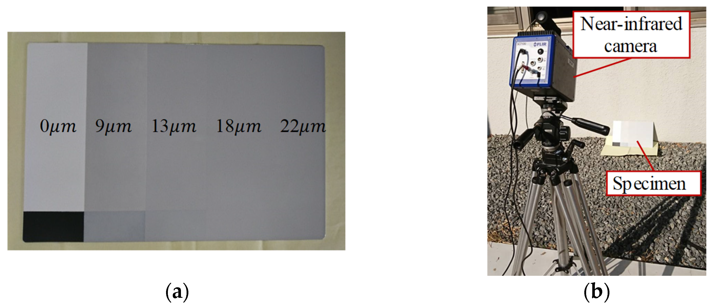
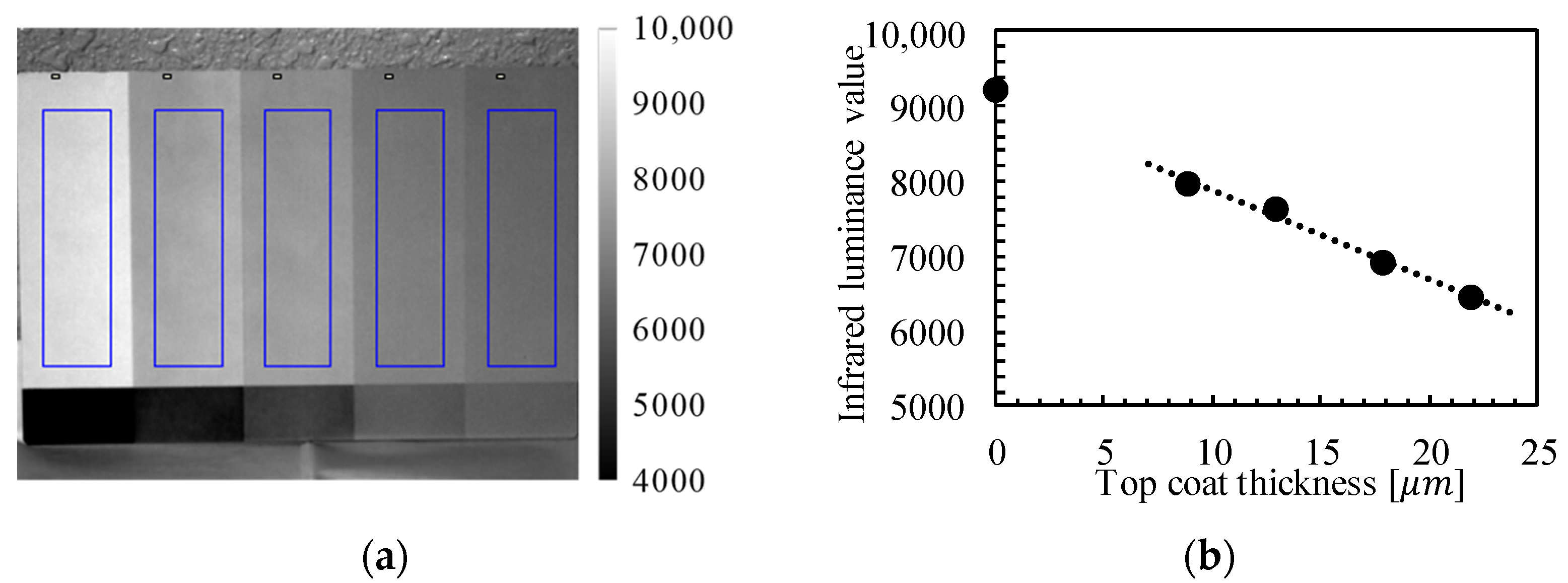
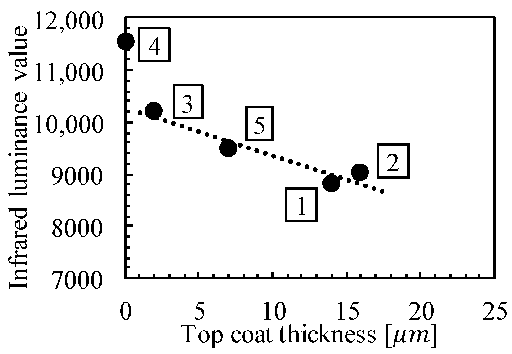
3. Experimental Result for the Specimen Having Various Thicknesses of Top Coat

Figure 3a shows the specimen having various thicknesses of top coat used in this study. The specimen consists of an intermediate coat of epoxy resin on the steel surface and a top coat of fluoropolymer resin on the intermediate coat. The top coat was painted in five different thicknesses. The thickness values of the top coat are indicated in the figure, and each value is the average of five measurements obtained by using a paint-cutter type coating thickness gauge. The leftmost specimen was not painted with the top coat, exposing the intermediate coat. This study used the near-infrared camera with InGaAs array detector and spectral response of 900–1700 nm. Figure 3b shows the experimental setup with the near-infrared camera and specimen. Infrared measurements were conducted under continuous sunlight on the specimen. The temperature change due to the sunlight exposure did not cause any effect on the short wave infrared reflection measurement.
Figure 4a shows an infrared image of the specimen. It is found that the infrared intensity in the top coat decreases as the thickness of the top coat increases. To quantitatively evaluate the difference in infrared intensity depending on the thickness of the top coat, the authors obtain the relationship between each thickness of the top coat and the average value of infrared intensity in the blue frame of the infrared images shown in Figure 4a. Figure 4b shows the relationship of each thickness of the top coat and the infrared intensity. From the figure, both relationships show the linearity. Therefore, it is concluded that the thickness of the top coat can be quantitatively evaluated using the calibration relationship for the top coat in the bridges in-service.

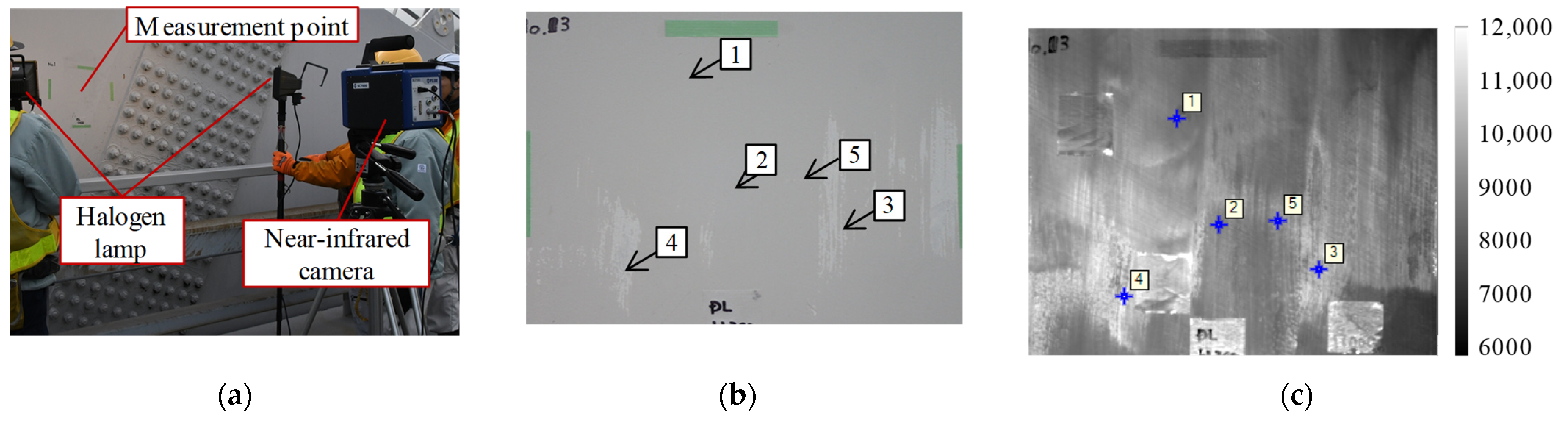
4. Experimental Result for the Bridge in-Service

Infrared measurements of the thickness of top coats were conducted on the bridge in-service. The objective bridge is a long-span arch steel bridge that has been in service since 1979. The top coat of the bridge was repainted in 1992. It should be noted that the heavy-duty anticorrosion coating of the bridge was made using paint with a different infrared absorption spectrum from that of the specimen shown in the foregoing section. The measurement points for the bridge were set on the arch ribs. Figure 5a shows the experimental setup with the near-infrared camera and halogen lamp on the bridge. Infrared measurements were conducted under sunlight as in the experiments of the previous section. However, the light intensity was insufficient, so the authors irradiated the measurement points with a halogen lamp as supplementary light.
The visible image and infrared image of the measured points are shown in Figure 5. In the infrared image, the exposed area of the intermediate coat could be detected more clearly than in the visible image. It is also found that the infrared intensity is changed in the area where the top coat is remained. Therefore, the authors investigated the relationship between the remaining thickness of the top coat measured by the micro-destructive method and the infrared intensity on the five locations in the figure. Figure 6 shows the relationship between the remaining thickness of the top coat and the infrared intensity. It is found from the relationship that the thicker the remaining thickness of the top coat, the lower the infrared intensity of that, as with the specimen in the previous section. Moreover, a linear relationship between the remaining thickness of the top coat and the infrared intensity of that was also confirmed. The use of infrared illumination, such as halogen lamps, eliminated the effects of insufficient light intensity and shadows due to the bridge members in the bridges in service.

5. Conclusions

In this study, the authors focused on the relationship between the remaining thickness of the top coat and the infrared intensity in the near-infrared measurement and conducted experimental studies on specimens and bridges. It was found that there was a correlation between the top coat thickness and the infrared intensity and that this calibration relationship could be used to estimate the top coat thickness.

Funding

The authors would like to acknowledge that the research works shown in this paper were partly supported by a Grant-in-Aid for Scientific Research from the Japan Society for the Promotion of Science (B: 26289009 and B: 21H01213).

Data Availability Statement

The datasets that support the findings during the current study available from the corresponding author upon reasonable request.

References

  1. Sakagami, T. Remote nondestructive evaluation technique using infrared thermography for fatigue cracks in steel bridges. Fatigue Fract. Eng. Mater. Struct. 2015, 38, 755–779. [Google Scholar] [CrossRef]
  2. Sakagami, T.; Mizokami, Y.; Shiozawa, D.; Hayashi, M.; Takeguchi, M. Application of infrared camera for steel bridge maintenance. In Proceedings of the Thermosense: Thermal Infrared Applications XL, Orlando, FL, USA, 16–19 April 2018; Volume 10661. [Google Scholar]
Figure 1. Schematic diagram of the heavy-duty anticorrosion coating.
Engproc 08 00026 g001
Figure 2. Principle of measurement of the thickness of top coat by infrared reflected energy.
Engproc 08 00026 g002
Figure 3. (a) Specimen simulated heavy-duty anticorrosion coating, (b) Experimental setup of the specimen.
Engproc 08 00026 g003
Figure 4. (a) Infrared image of the specimen and the evaluation area in the blue frame, (b) Relationship between infrared luminance value and top coat thickness.
Engproc 08 00026 g004
Figure 5. (a) Experimental setup of the bridge, Measurement point of (b) visible image, (c) infrared image.
Engproc 08 00026 g005
Figure 6. Relationship between infrared luminance value and top coat thickness of the bridge.
Engproc 08 00026 g006
Publisher’s Note: MDPI stays neutral with regard to jurisdictional claims in published maps and institutional affiliations.

