Proceeding Paper

Personal Watercraft Remote Control Communication Fault Detection †

Department of Automotive and Railway Engineering, Széchenyi István University, Egyetem tér 1., 9026 Győr, Hungary
Presented at the Sustainable Mobility and Transportation Symposium 2024, Győr, Hungary, 14–16 October 2024.
Eng. Proc. 2024, 79(1), 8; https://doi.org/10.3390/engproc2024079008
Published: 29 October 2024
(This article belongs to the Proceedings of The Sustainable Mobility and Transportation Symposium 2024)

Abstract

:
Hydroflight is a watersport where the user utilizes a waterjet-propelled backpack to fly over water. These backpacks are usually powered by purpose-built equipment but can also be propelled by personal watercraft. To have full control over movement during hydroflight, the user needs to adjust the throttle of the watercraft, which is commonly performed by converting the system to remote-controlled operation. However, care should be taken during conversion to ensure safe operation and avoid harm to the user. This paper presents a failure analysis of sudden safety mode activation on a personal watercraft converted to remote control for hydroflight applications, as well as actions taken to avoid full shutdown in the case of communication loss, without compromising user safety.

1. Introduction

Hydroflight is a water-based extreme sport where riders use a water-propelled jetpack or board, powered by a high-pressure hose connected to a personal watercraft (PWC), to achieve flight above the water’s surface. Thanks to the rapid development of hydroflight sports, it is no longer necessary to buy expensive equipment specifically designed for this activity. Instead, a common PWC can be used to propel hydroflight devices. Flight is achieved by switching modes on the PWC, resulting in redirecting the fluid pumped by the jet-powered watercraft to the hydroflight device through a fluid tube. The signals necessary for mode switching, i.e., decoding the existing system, can pose significant challenges. In a conventional arrangement, the hydroflight user steers the hydroflight device (e.g., flyboard) while the throttle is controlled on the watercraft. In this scenario, the PWC’s seated throttle operator requires precise, skilled handling to perform the desired movements. However, this scenario can result in desynchronization between the hydroflight user and the throttle operator, making the development of remote control necessary for professional sports applications. Furthermore, modifying the intelligent brake and reverse (iBR) system for hydroflight mode can also be of relevance. For Sea-Doo watercraft, the engine’s maximum power output is only achieved by pressing the “SPORT” button on the handlebar twice after starting the PWC engine. In such cases, another development requirement can be to activate full-throttle mode immediately upon vehicle start-up.
Remote controlling hydroflight devices can pose further challenges and complications in the case of the loss of communication. Since the hydroflight user’s feet are secured to the hydroflight device with special boots (wakeboard boots), the user can only remove their feet when the boots are released. If the PWC engine is off, the hydroflight device and hose can pull the user underwater due to their weight and the lack of water pressure. High-altitude fall risk is another major hazard that the user is exposed to when using the device. For the above mentioned reasons, the remote communication system needs to have very high reliability. Hideaki et al. [1] report on the issue of limited communication and message loss during remote message transfer. The challenges of remote-controlled surface vessels have been elaborated on by numerous researchers [2,3,4,5,6,7], addressing the communication hierarchy, tools, and potential advantages of such devices. Additional challenges include sudden signal loss and signal shading. Chang et al. [8] discuss wireless communication interference, while Prukner and Kuczmann [9], Zuffanelli [10], and Balanis [11] address the selection of appropriate materials, measurements, and designs for remote control applications.
This technical paper presents the challenges of converting a PWC for remote-controlled hydroflight applications, as a cost-effective alternative compared to purpose-built solutions.

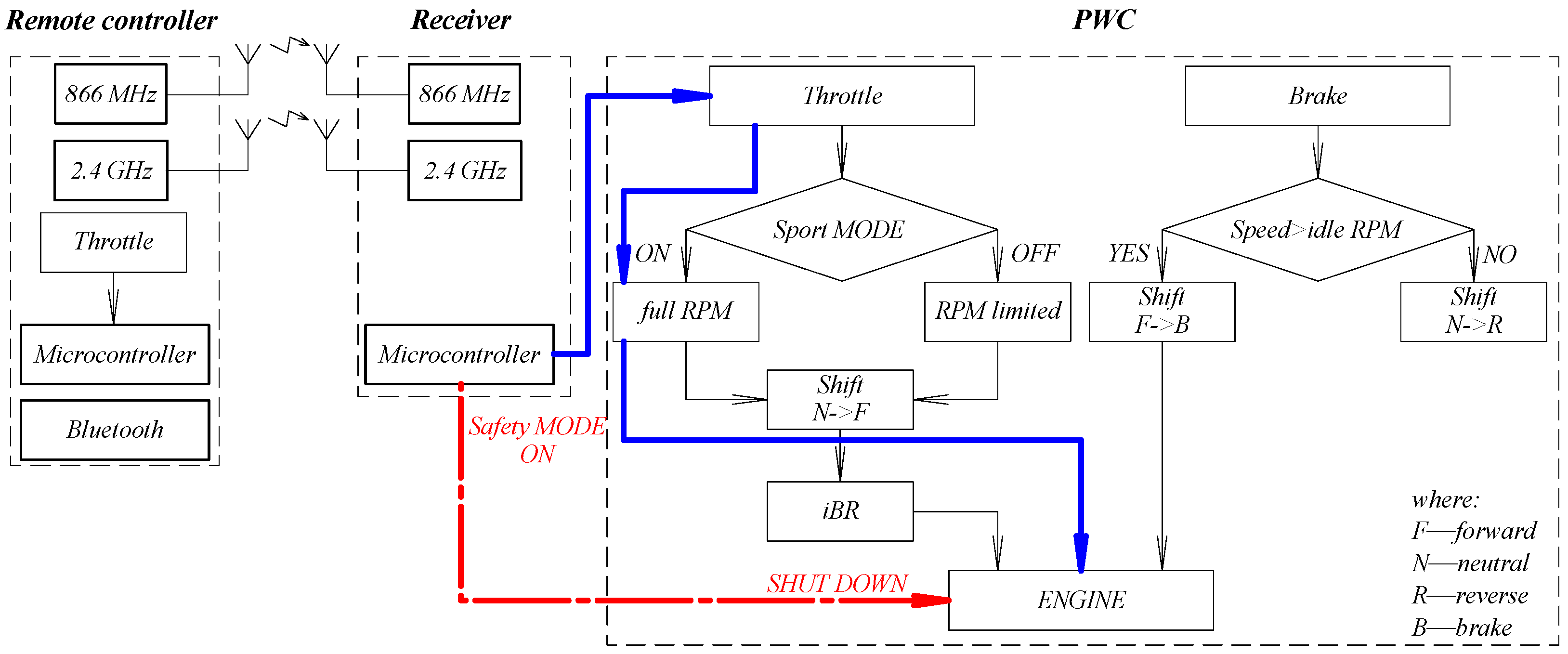
2. Materials and Methods

The main steps of developing the remote-controlled PWC selected for conversion for hydroflight application included the decoding of the PWC’s communication schemes, overriding the brake and reverse system, activating full-throttle mode, and remotely controlling the throttle, as depicted in Figure 1. These steps were implemented on a Sea-Doo PWC augmented with a 2.4 GHz remote controller and receiver.
During the study, a thorough inspection of the aftermarket remote controller was necessary, due to the random shutdown events of the PWC, initiated by an unexpected “safety system activation”. According to the provided documentation, the system includes dual-frequency communication and a “safety MODE”, which serves to shut down the PWC engine in case of an emergency. The PWC system communicates using CAN-BUS protocol. The remote control was integrated into the CAN-BUS, ensuring precise and safe communication between the PWC and the hydroflight user. According to Figure 2, the remote control communicates with the receiver installed in the PWC, which can directly send signals to the PWC’s ECU system, thus enabling remote control (blue lines).
In Figure 2, the red line indicates control in “safety MODE”. The black line shows the data lines required for basic system operation.

3. Results

The cause of the experienced shutdown can be traced back to several factors, necessitating a step-by-step investigation. Possible sources of failure include incorrect material use, remote controller malfunction, and machining precision issues (Figure 3).

3.1. Remote Controller Machining Tolerance

The remote uses a Hall sensor to detect the throttle position. The magnetic response is set up to the operating limit based on the design. However, according to the tests, some remotes may encounter an issue due to manufacturing tolerances, where the operating limit is exceeded, triggering the “safety MODE”.
In this case, the system detected an error, resulting in the shutdown of the PWC engine. The further the value of Δs is from the operating limit, the more maximum throttle is lost. The effective Δs is a result of magnet position, trigger position, and sensor position (Figure 4).
In the error analysis of manufacturing parameters, a mathematical method was applied, specifically the total sensitivity analysis [12]. In this context, a scalar–vector function F(p) was considered, a real-valued function representing the quality characteristics of the remote in terms of machining tolerance. The real variable p is the manufacturing parameter vector. The change in F(p) with respect to p was observed. This function depends on the n manufacturing parameters, and any change to these parameters can significantly affect the quality characteristic. The maximum effect of all parameters in relation to p was sought. In a sensitivity analysis, the change in F(p) is characterized when p changes with a discrete amount of dp. S(p) represents the percentage change (1).
S p = 100 ( F p + d p F p ) F ( p )
To characterize the change in F(p) when p changes by 1%, the length of dp is chosen to be 1% of the length of p (2).
d p = 0.01 | p |
Since dp is a vector, specifying only its magnitude is insufficient; its direction must also be defined. The direction of the most critical, maximum change is sought, which occurs in the direction of the gradient vector at point p. Therefore, the unit gradient vector at point “p” is multiplied by 0.01 |p| (3).
d p = 0.01 g r a d ( F p ) p g r a d ( F p )
Next, the directional derivative of the function F(p) is expressed in the direction determined by dp (4).
I _ d p p : = F p + d p F ( p ) d p
Let us also form the function T(p) below (5).
T p : = 100 d p F ( p )
The product of (4) and (5) defines the S(p) function for sensitivity analysis (6).
S p = I _ d p p T ( p )
The directional derivative in the direction of the gradient can also be determined, by definition, as the scalar product of the gradient unit vector and the gradient vector (7).
I _ d p p : = g r a d ( F p ) 2 g r a d ( F p )
I _ d p p : = g r a d ( F p )
Considering (2) and (5), one can arrive at a different expression of T(p) (9).
T : = p F ( p )
Using (9), the maximal sensitivity is given (10).
S p : = g r a d ( F p ) p F ( p )
Equation (10) gives the maximum percentage change in the function F(p) at any arbitrary point p, if p changes by 1% in the critical direction. Reducing manufacturing tolerances leads to a significant increase in production costs, while matching components with different tolerances would require additional time. As a result, after completing the investigation, software development was recommended to counteract the problem caused by tolerances. This would allow for individual remote controller calibration to eliminate the distance fluctuations caused by sensor manufacturing variations. The calibration option is implemented through a custom software solution via a Bluetooth unit. Setting the “limit” to the specified “north-0mT” value is allowed by the software calibration; we just have to fully pull the remote controller trigger and the system overrides the “limit” “position” to correct the level. Due to the software development (one-off fee), it is not necessary to continue to increase manufacturing accuracy and component matching (fixed charges) to ensure production tolerance.

3.2. Remote Housing Shading

A large part of the remote controller housing is made of carbon fiber, which has known signal-shading properties. Furthermore, the receiver unit is located inside the PWC, which is surrounded by various sources of possible interference. Therefore, an investigation was requested to detect any potential data loss within a 20 m radius from the PWC in a unidirectional manner, including above the PWC. Due to the economic and implementation challenges of conducting this investigation, an alternative solution was chosen by analyzing and running the source software (Figure 5).
The “safety MODE” is activated during sudden signal loss (left, Figure 5a), causing the PWC engine to shut down (upper right, Figure 5b). To alleviate this, the source software was modified to include a 1 s buffer time, resulting in the PWC throttle remaining at its pre-signal-loss position for up to 1 s (lower right, Figure 5c) during sudden signal loss. Moreover, if the signal is not re-established after 1 s, the throttle is gradually reduced to idle instead of immediately stalling. This safety measure ensures the gradual lowering of the user back to surface level.

3.3. Software Audit

To find all possible root causes of sudden signal loss, a complete review of the software was conducted. The investigation focused on the unexpected activation of “safety MODE” during use. While investigating the communication error, error messages were logged through the CAN-BUS. The investigation revealed that the software was using the internal clock of the processor instead of the external real-time clock, resulting in a timing discrepancy, which triggered the activation of “safety MODE”.

4. Conclusions

Through conducting an investigation involving various engineering fields, a simple, cost-effective failure analysis was performed, and actions were defined to alleviate the encountered causes. The initially proposed signal testing process was replaced with a simpler software configuration approach. As a result of the investigation, the initially defined problem was solved by implementing a sensor calibration routine on the remote controller, and a signal loss buffer for the receiver.
Sensor calibration ensures that the throttle sensor reading is compared to the actual range of the specific remote, rather than pre-set ranges. This prevents out-of-bound errors and safety activations caused by inaccurate machining tolerances. When an unexpected “safety MODE” activation still occurs, the PWC’s engine no longer shuts down completely. Instead, the throttle is gradually reduced to idle, preventing the user from falling off and submerging.

Funding

This research received no external funding.

Institutional Review Board Statement

Not applicable.

Informed Consent Statement

Not applicable.

Data Availability Statement

Data for this study are not publicly available.

Conflicts of Interest

The authors declare no conflicts of interest.

References

  1. Ishii, H.H. Control with limited communication and message losses. Syst. Control Lett. 2008, 57, 322–331. [Google Scholar] [CrossRef]
  2. Dudnikov, S.Y.; Vertegel, V.V.; Golovin, V.V.; Tyschuk, Y.N. Remote control system for the unmanned floating platform. In Proceedings of the IOP Conference Series: Materials Science and Engineering, Tel Aviv, Israel, 21–23 February 2021. [Google Scholar] [CrossRef]
  3. Guo, W.; Wang, S.; Dun, W. The Design of a Control System for an Unmanned Surface Vehicle. Open Autom. Control Syst. J. 2015, 7, 150–156. [Google Scholar] [CrossRef]
  4. Stateczny, A.; Burdziakowski, P. Universal Autonomous Control and Management System for Multipurpose Unmanned Surface Vessel. Pol. Marit. Res. 2019, 26, 30–39. [Google Scholar] [CrossRef]
  5. Mickhayluck, Y.P.; Iskiv, V.M.; Golovin, V.V.; Schekaturin, A.A.; Afonin, I.L.; Gimpilevich, Y.B. Study of the possibility of using the communication system with IEEE 802.22 for remote control of an unmanned vessel. In Proceedings of the 2017 IEEE International Conference on Microwaves, Antennas, Communications and Electronic Systems (COMCAS), Tel Aviv, Israel, 13–15 November 2017. [Google Scholar] [CrossRef]
  6. Tyschuk, Y.; Vertegel, V.; Nikiforov, S.; Nesterenko, A. Development and Implementation of a Remote-Control System for an Unmanned Research Small Vessel. Transp. Res. Proc. 2023, 68, 395–401. [Google Scholar] [CrossRef]
  7. Afonin, I.L.; Iskiv, V.M.; Mickhayluck, Y.P.; Redkina, E.A.; Tian, N.G.; Schekaturin, A.A. Principles of designing the digital radio electronics system for unmanned vessel remote control. In Proceedings of the 26th International Conference Microwave and Telecommunication Technologies (CriMiCo 2016), Sevastopol, Russia, 4–10 September 2016. [Google Scholar]
  8. Chang, X.; Li, Y.; Wang, Z. Accuracy-aware interference modeling and measurement in wireless sensor networks. IEEE Trans. Mob. Comput. 2016, 15, 278–291. [Google Scholar] [CrossRef]
  9. Prukner, P.; Kuczmann, M. Applications of periodic structures and metamaterials for antenna design. Acta Tech. Jaurinensis 2022, 15, 188–192. [Google Scholar] [CrossRef]
  10. Zuffanelli, S. Antenna Design Solutions for RFID Tags Based on Metamaterial-Inspired Resonators and Other Resonant Structures; Springer International Publishing AG: Cham, Switzerland, 2017. [Google Scholar]
  11. Balanis, C.A. Antenna Theory: Analysis and Design, 3rd ed.; Wiley: New York, NY, USA, 2016. [Google Scholar]
  12. Péter, T. Komplex célfüggvény és ekvivalencia osztályok alkalmazása gépjármű lengőrendszerek térbeli sztochasztikus modelljeinek optimálására. In Proceedings of the Magyarok Szerepe a Világ Természettudományos és Műszaki Haladásában III, Tudományos találkozó, Budapest, Hungary, 14–18 August 1992. [Google Scholar]
Figure 1. Development steps of remote-controlled PWC.
Engproc 79 00008 g001
Figure 2. Block diagram of the system.
Engproc 79 00008 g002
Figure 3. The fault diagnostic steps.
Engproc 79 00008 g003
Figure 4. Magnetic response for Hall effect sensor, considering the manufacturing tolerances.
Engproc 79 00008 g004
Figure 5. (a) Loss of signal from the remote control. Software behavior of the receiver before (b) and after (c) implementing buffer time.
Engproc 79 00008 g005
Disclaimer/Publisher’s Note: The statements, opinions and data contained in all publications are solely those of the individual author(s) and contributor(s) and not of MDPI and/or the editor(s). MDPI and/or the editor(s) disclaim responsibility for any injury to people or property resulting from any ideas, methods, instructions or products referred to in the content.

